relay MITSUBISHI ECLIPSE 1990 Workshop Manual
[x] Cancel search | Manufacturer: MITSUBISHI, Model Year: 1990, Model line: ECLIPSE, Model: MITSUBISHI ECLIPSE 1990Pages: 391, PDF Size: 15.27 MB
Page 355 of 391
23-38BODY - Seat Belts
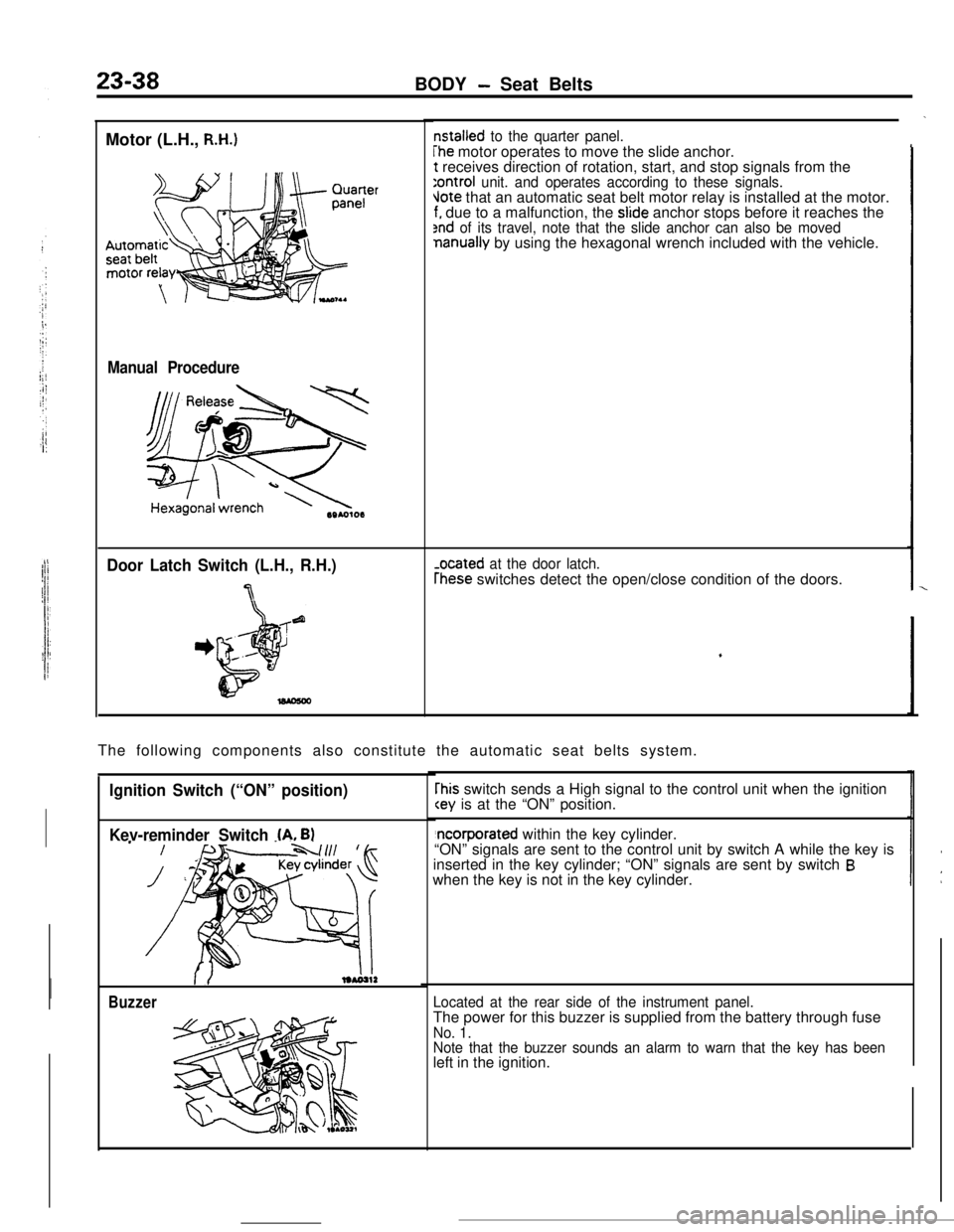
Motor (L.H.,
R.H.)
Manual Procedure
Door Latch Switch (L.H., R.H.)
7
nstalled to the quarter panel.
The motor operates to move the slide anchor.t receives direction of rotation, start, and stop signals from the
:ontroi unit. and operates according to these signals.Jote that an automatic seat belt motor relay is installed at the motor.f. due to a malfunction, the slide anchor stops before it reaches the2nd of its travel, note that the slide anchor can also be movednanually by using the hexagonal wrench included with the vehicle.
-ocated at the door latch.
rhese switches detect the open/close condition of the doors.
The following components also constitute the automatic seat belts system.
Ignition Switch (“ON” position)
Kev-reminder Switch
(A. B)
Buzzer
rhis switch sends a High signal to the control unit when the ignition
“ON” signals are sent to the control unit by switch A while the key is
inserted in the key cylinder; “ON” signals are sent by switch
Bwhen the key is not in the key cylinder.
Located at the rear side of the instrument panel.The power for this buzzer is supplied from the battery through fuse
No. 1.
Note that the buzzer sounds an alarm to warn that the key has beenleft in the ignition.
Page 371 of 391
-.-- ----_-
24-8HEATERS AND AIR CONDITIONING - Compressor
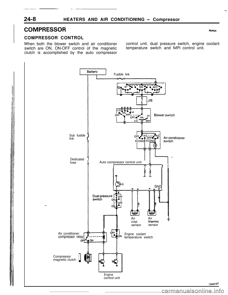
COMPRESSORR24GbCOMPRESSOR CONTROL
When both the blower switch and air conditioner
switch are ON, ON-OFF control of the magnetic
clutch is accomplished by the auto compressorcontrol unit. dual pressure switch, engine coolant
temperature switch and
MPI control unit.
Sub fusible
link
Dedicatedfuse
Air conditioner
compressor relayrOFfCompressor
magnetic clutch
q l
Fusible link
lgnitionsyhWqb 1Auto compressor control unit
ITT1 I
0 bIAirAir
inlettherm0
4sensorsensor
Engine coolanttemperature switch
Enginecontrol unit13A0167
Page 372 of 391
19/---..-_HEATERS AND AIR CONDITIONING
- Idle Speed Control24-9
Ii” E SPEED CONTROL
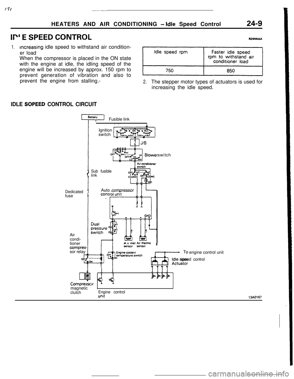
1.increasing idle speed to withstand air condition-
er load
When the compressor is placed in the ON state
with the engine at idle, the idling speed of the
engine will be increased by approx. 150 rpm to
prevent generation of vibration and also to
prevent the engine from stalling.-
2.The stepper motor types of actuators is used for
increasing the idle speed.
IDLE SOPEED CONTROL CIRCUITFusible link
Dedicatedfuse
Air
condi-tioner
compressor relay
I-gcfc
Lll
Compre:Ignition
switch
Sub fusible
linkswitch
Auto compressor
As
mlef kr Ihemo
Ax;,: engine control unit
Idle speed control
Y *e:Q
1
$4.1111.Pk+F)rmagneticIJ
clutchEngine controlunit13AO167
Page 380 of 391
-.-
25-6EMISSION CONTROL SYSTEMS- Exhaust Gas Recirculation (EGR) System
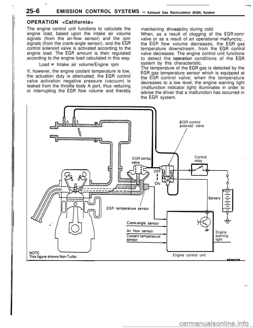
OPERATION
The engine control unit functions to calculate the
engine load, based upon the intake air volume
signals (from the air-flow sensor) and the rpm
signals (from the crank-angle sensor), and the
EGRcontrol solenoid valve is activated according to the
engine load. The
EGR amount is then regulated
according to the engine load calculated in this way.maintaining driveability during cold.
When, as a result of clogging of the
EGR cant’valve or as a result of an operational
malfunctio,.,the
EGR flow volume decreases, the EGR gas
temperature downstream. from the
EGR control
valve decreases. The engine control unit functions
to detect the
operation conditions of the EGRLoad
a Intake air volume/Engine rpmsystem by this characteristic.
If, however, the engine coolant temperature is low,
the actuation duty is attenuated, the
EGR control
valve activation negative pressure (vacuum) is
leaked from the throttle body A port, thus reducing
or interrupting the
EGR flow volume and therebyThe temperature of the
EGR gas is detected by the
EGR gas temperature sensor which is equipped at
the
EGR control valve; when the temperature
decreases to a low level, the engine warning light
(malfunction indicator light) illuminates in order to
advise the driver that a malfunction has occurred in
the
EGR system.
EGR
contcEGR control
solenoid valve
/Control
relay
1Engine control unit
Enginewarning
light
Page 382 of 391
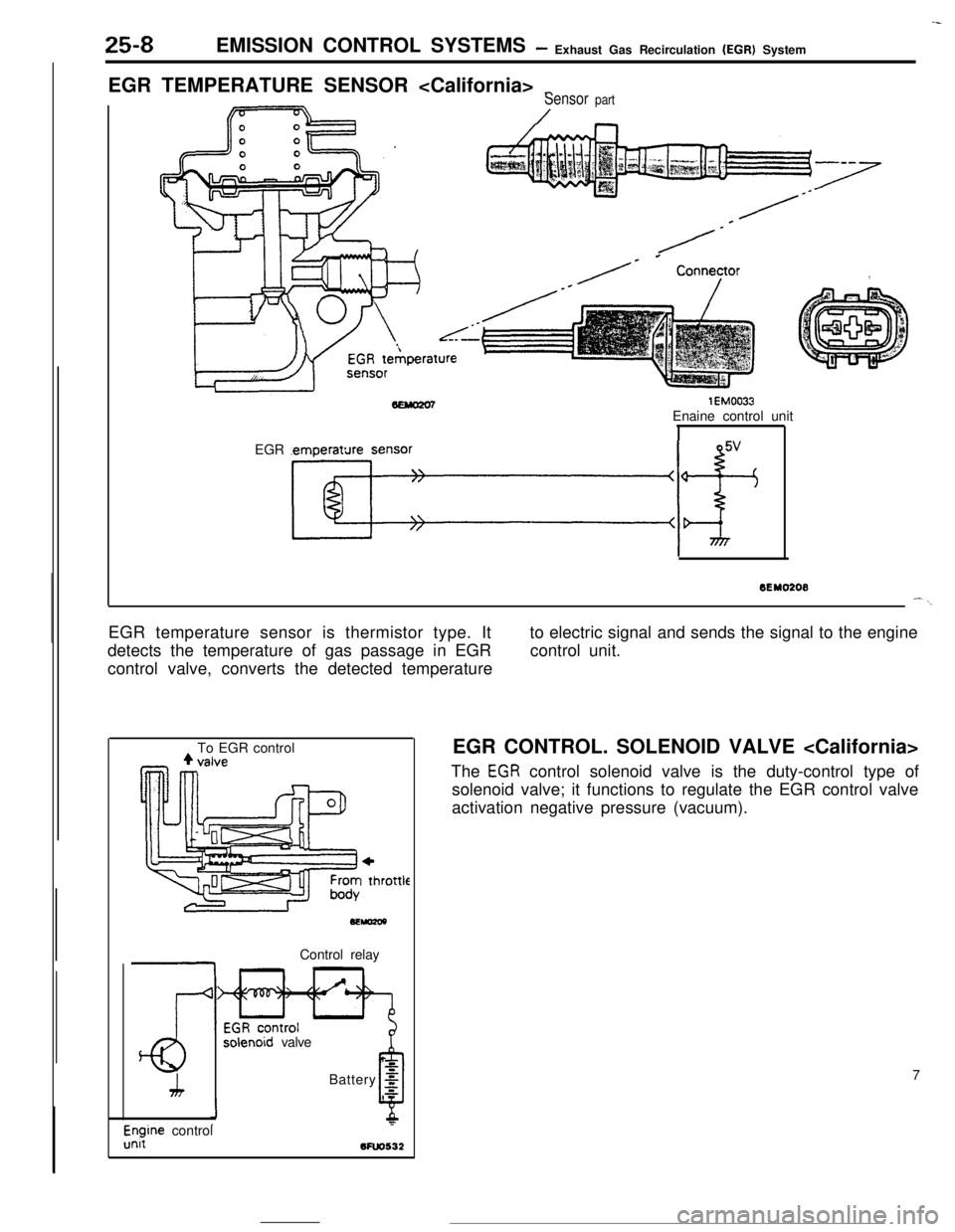
25-8EMISSION CONTROL SYSTEMS- Exhaust Gas Recirculation (EGR) System
EGR TEMPERATURE SENSOR
_Sensor part
/
/-
/* * Conneyor,
lEM0033Enaine control unit
EGR temperature sensor
Kf+
--
6EY0208--\EGR temperature sensor is thermistor type. It
detects the temperature of gas passage in EGR
control valve, converts the detected temperatureto electric signal and sends the signal to the engine
control unit.
To EGR control
+I thl
.ottleControl relay
solenoid valve
h
LBattery
g
0s
l$ine control5FW532EGR CONTROL. SOLENOID VALVE
The
EGR control solenoid valve is the duty-control type of
solenoid valve; it functions to regulate the EGR control valve
activation negative pressure (vacuum).
7
Page 387 of 391

EMISSION CONTROL SYSTEMS- Evaporative Emission Control System25-13
IFrom canister1
,To intake air plenum or throttle body
7EMOlPControl
relavPurge control
solenoid valve
Battery
g
6
,zEngine control
unit
From throttle body
4To purge
control
valve
SEMo2laControl relay
3:
1.
Purge control
solenoid valve
zBattery g
Engtne controlunii
bfuo532JPURGE CONTROL SOLENOID VALVE
The purge-control solenoid valve is the ON/OFF control type of
solenoid valve; it functions to control the introduction of purge
air to the intake air plenum from the canister.
PURGE CONTROL SOLENOID VALVE
The purge-control solenoid valve is the ON/OFF control type of
solenoid valve; it functions to control the activation of the
purge-control valve.
ITo throttle body11PURGE CONTROL VALVE
The purge-control valve functions to control the introduction of
purge air to the air-intake hose from the canister.
0 From canister