relay MITSUBISHI ECLIPSE 1990 Owner's Guide
[x] Cancel search | Manufacturer: MITSUBISHI, Model Year: 1990, Model line: ECLIPSE, Model: MITSUBISHI ECLIPSE 1990Pages: 391, PDF Size: 15.27 MB
Page 158 of 391
.
14-46FUEL SYSTEM- Idle Speed Control
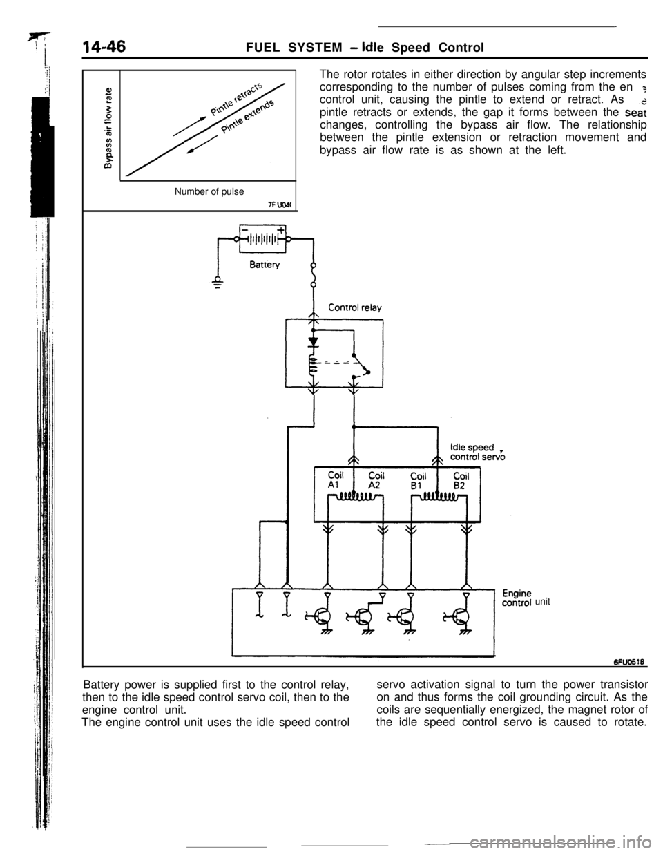
The rotor rotates in either direction by angular step increments
corresponding to the number of pulses coming from the en
?control unit, causing the pintle to extend or retract. As
pintle retracts or extends, the gap it forms between the
sea:changes, controlling the bypass air flow. The relationship
between the pintle extension or retraction movement and
bypass air flow rate is as shown at the left.
Number of pulse
7F UW(Control relay
@iI---
unit
Battery power is supplied first to the control relay,
then to the idle speed control servo coil, then to theservo activation signal to turn the power transistor
engine control unit.on and thus forms the coil grounding circuit. As the
The engine control unit uses the idle speed controlcoils are sequentially energized, the magnet rotor of
the idle speed control servo is caused to rotate.
Page 166 of 391
FUEL SYSTEM- Power Supply Control
Battery
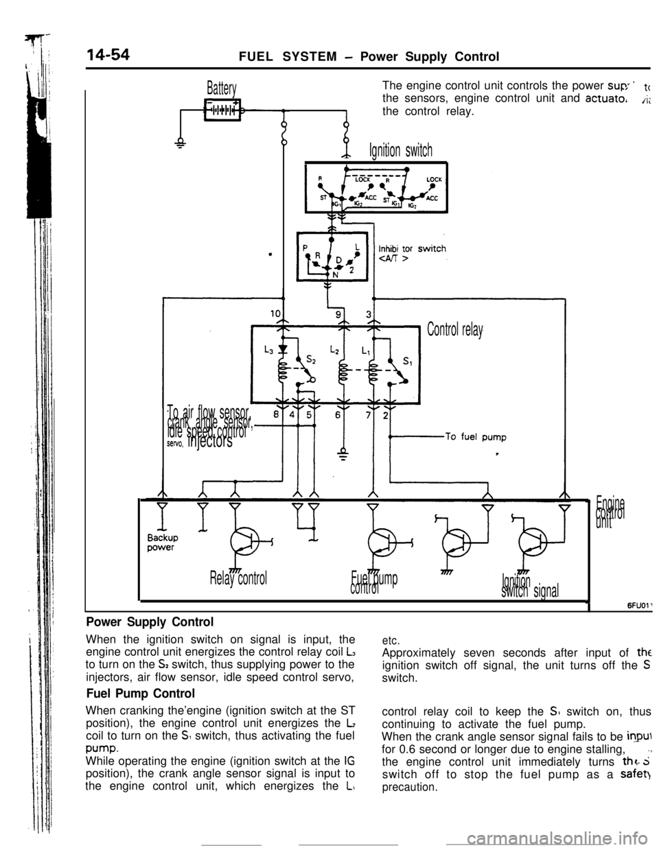
L11The engine control unit controls the power
suv ’tcthe sensors, engine control unit and
actuate,A;the control relay.
-P
.
-p.Ignition switch
Inn yr
To air flow sensor,crank angle sensor,idle speed controlsetvo. injectors
Control relay
Relay controlFuel pump
controlIgnitionswitch signal
Enginecontrol
unit
I6FUOl’
Power Supply ControlWhen the ignition switch on signal is input, the
engine control unit energizes the control relay coil
L3to turn on the
S2 switch, thus supplying power to the
injectors, air flow sensor, idle speed control servo,
Fuel Pump ControlWhen cranking the’engine (ignition switch at the ST
position), the engine control unit energizes the
Lcoil to turn on the
S switch, thus activating the fuel
pump.While operating the engine (ignition switch at the
IGposition), the crank angle sensor signal is input to
the engine control unit, which energizes the
L,
etc.Approximately seven seconds after input of
theignition switch off signal, the unit turns off the
Sswitch.
control relay coil to keep the
SI switch on, thus
continuing to activate the fuel pump.
When the crank angle sensor signal fails to be
inputfor 0.6 second or longer due to engine stalling,
.,the engine control unit immediately turns
thz. 5switch off to stop the fuel pump as a safet)
precaution.
Page 167 of 391
FUEL SYSTEM -Air Conditioner Relay Control14-55AIR CONDITIONER RELAY CONTROL
Batterylgnltlon
switch
Air conditionerswitch
@OFF ON
Coolanttemperature
switch
RlUCAAA
/Air condittoner
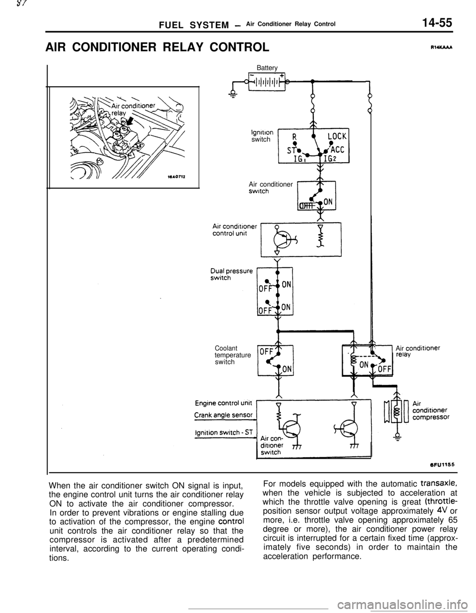
When the air conditioner switch ON signal is input,
the engine control unit turns the air conditioner relay
ON to activate the air conditioner compressor.
In order to prevent vibrations or engine stalling due
to activation of the compressor, the engine control
unit controls the air conditioner relay so that the
compressor is activated after a predetermined
interval, according to the current operating condi-
tions.For models equipped with the automatic
transaxle,when the vehicle is subjected to acceleration at
which the throttle valve opening is great (throttle-
position sensor output voltage approximately
4V or
more, i.e. throttle valve opening approximately 65
degree or more), the air conditioner power relay
circuit is interrupted for a certain fixed time (approx-
imately five seconds) in order to maintain the
acceleration performance.
Page 168 of 391
14-56FUEL SYSTEM -Supercharge Pressure Control
SUPERCHARGEPRESSURE CONTROL
sensor
lEngine control
unit
Knockcontrol
ControlrelayIntercooler
h&l --/I- h
.. .Waste gate
P solenoid valve
Air cleaner,
Power
transistorWaste gate
unit
actuatorOf
CT1 +p$?V~~~t
6FUO665
II\Spring set pressure
Turbo pressure acting5Fuo570
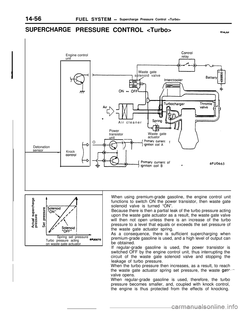
on waste gate actuatorWhen using premium-grade gasoline, the engine control unit
functions to switch ON the power transistor, then waste gate
solenoid valve is turned “ON”.
Because there is then a partial leak of the turbo pressure acting
upon the waste gate actuator as a result, the waste gate valve
will then not open unless there is an increase of the turbo
pressure to a level that equals or exceeds the set pressure of
the waste gate actuator spring.
As a consequence, there is sufficient supercharging when
premium-grade gasoline is used, and a high level of output can
be obtained.
If regular-grade gasoline is used, the power transistor is
switched OFF by the engine control unit, thus interrupting the
circuit of the waste gate solenoid valve and stopping the
leakage of turbo pressure.
When the turbo pressure then increases, as a result, to reach
the waste gate actuator spring set pressure, the waste
gate----valve opens.
When regular-grade gasoline is used, therefore, the turbo
pressure becomes smaller, and, coupled with knock control,
the engine is thus protected from the effects of knocking.
Page 169 of 391
FUEL SYSTEMAir Flow Sensor (AFSI Filter Reset Control
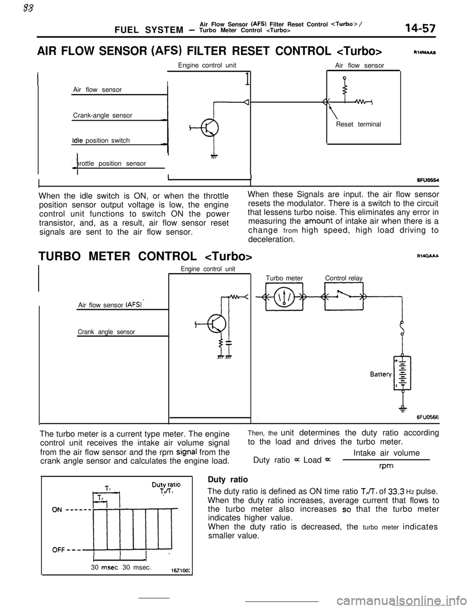
AIR FLOW SENSOR (AFS) FILTER RESET CONTROL
I1Air flow sensor
Crank-angle sensorIdle position switch
Throttle position sensor
4Air flow sensor
//\\ -
\Reset terminal
RllruAs
6FlJo664I11When the idle switch is ON, or when the throttleWhen these Signals are input. the air flow sensor
position sensor output voltage is low, the engineresets the modulator. There is a switch to the circuit
control unit functions to switch ON the powerthat lessens turbo noise. This eliminates any error in
transistor, and, as a result, air flow sensor resetmeasuring the
.amount of intake air when there is a
signals are sent to the air flow sensor.change from high speed, high load driving to
deceleration.
TURBO METER CONTROL
Air flow sensor
(AFSI ’
Crank angle sensorEngine control unit
BT
Rl4QAAATurbo meterControl relay
The turbo meter is a current type meter. The engine
control unit receives the intake air volume signal
from the air flow sensor and the rpm
signal from the
crank angle sensor and calculates the engine load.Then, the unit determines the duty ratio according
to the load and drives the turbo meter.
Intake air volume
Duty ratio
it Load 0:rwDuty ratio
The duty ratio is defined as ON time ratio
TJT, of 33.3 Hz pulse.
When the duty ratio increases, average current that flows to
the turbo meter also increases
so that the turbo meter
indicates higher value.
When the duty ratio is decreased, the turbo meter indicates
smaller value.
cI30
msec. 30 msec.1621cm:
Page 271 of 391
AUTOMATIC TRANSAXLE - Transaxle Control21-47
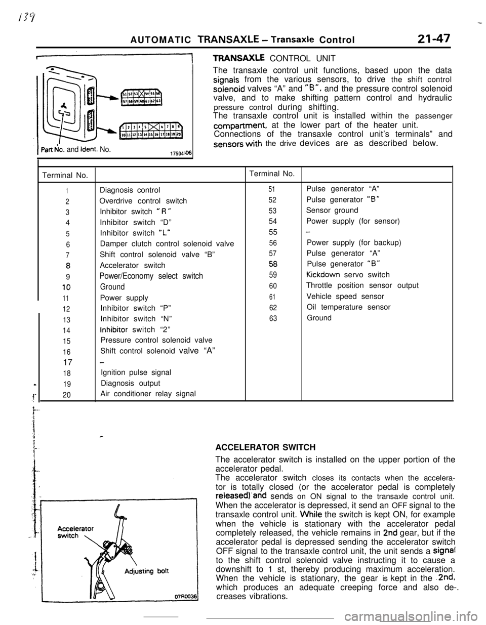
+TFWNSAXLE CONTROL UNIT
Part b!o. and Ident. No.17504The transaxle control unit functions, based upon the data
signals from the various sensors, to drive the shift controlsolenoid valves “A” and
“B”, and the pressure control solenoid
valve, and to make shifting pattern control and hydraulic
pressure control during shifting.
The transaxle control unit is installed within the passengercompartment, at the lower part of the heater unit.
Connections of the transaxle control unit’s terminals” and
sensors with the drive devices are as described below.
Terminal No.Terminal No.
1Diagnosis control51Pulse generator “A”
2Overdrive control switch52Pulse generator “B”
3Inhibitor switch e R U53Sensor ground
4Inhibitor switch “D”
54Power supply (for sensor)
5Inhibitor switch “L”55 -
6Damper clutch control solenoid valve56Power supply (for backup)
7Shift control solenoid valve “B”57Pulse generator “A”
8Accelerator switch58Pulse generator “B”
9Power/Economy select switch59Kickdown servo switch
10Ground60Throttle position sensor output
11Power supply61Vehicle speed sensor
12Inhibitor switch “P”62Oil temperature sensor
13Inhibitor switch “N”63Ground
14inhibitor switch “2”
15Pressure control solenoid valve
16Shift control solenoid valve “A”
17
-
18Ignition pulse signal
19Diagnosis output
20Air conditioner relay signal
rACCELERATOR SWITCH
The accelerator switch is installed on the upper portion of the
accelerator pedal.
The accelerator switch closes its contacts when the accelera-
tor is totally closed (or the accelerator pedal is completelyreieasedj‘and sends on ON signal to the transaxle control unit.
When the accelerator is depressed, it send an OFF signal to the
transaxle control unit. Whiie the switch is kept ON, for example
when the vehicle is stationary with the accelerator pedal
completely released, the vehicle remains in
2nd gear, but if the
accelerator pedal is depressed sending the accelerator switch
OFF signal to the transaxle control unit, the unit sends a signal
to the shift control solenoid valve instructing it to cause a
downshift to 1 st, thereby producing maximum acceleration.
When the vehicle is stationary, the gear is kept in the .2nd,
which produces an adequate creeping force and also de-.
creases vibrations.
Page 274 of 391
21-50AUTOMATIC TRANSAXLE - Transaxle Control
Vehicle
sensorspeedTerminal voltage
(VI
1
5
\*Fluidtemperature
02080PCI 1750409VEHICLE-SPEED SENSOR
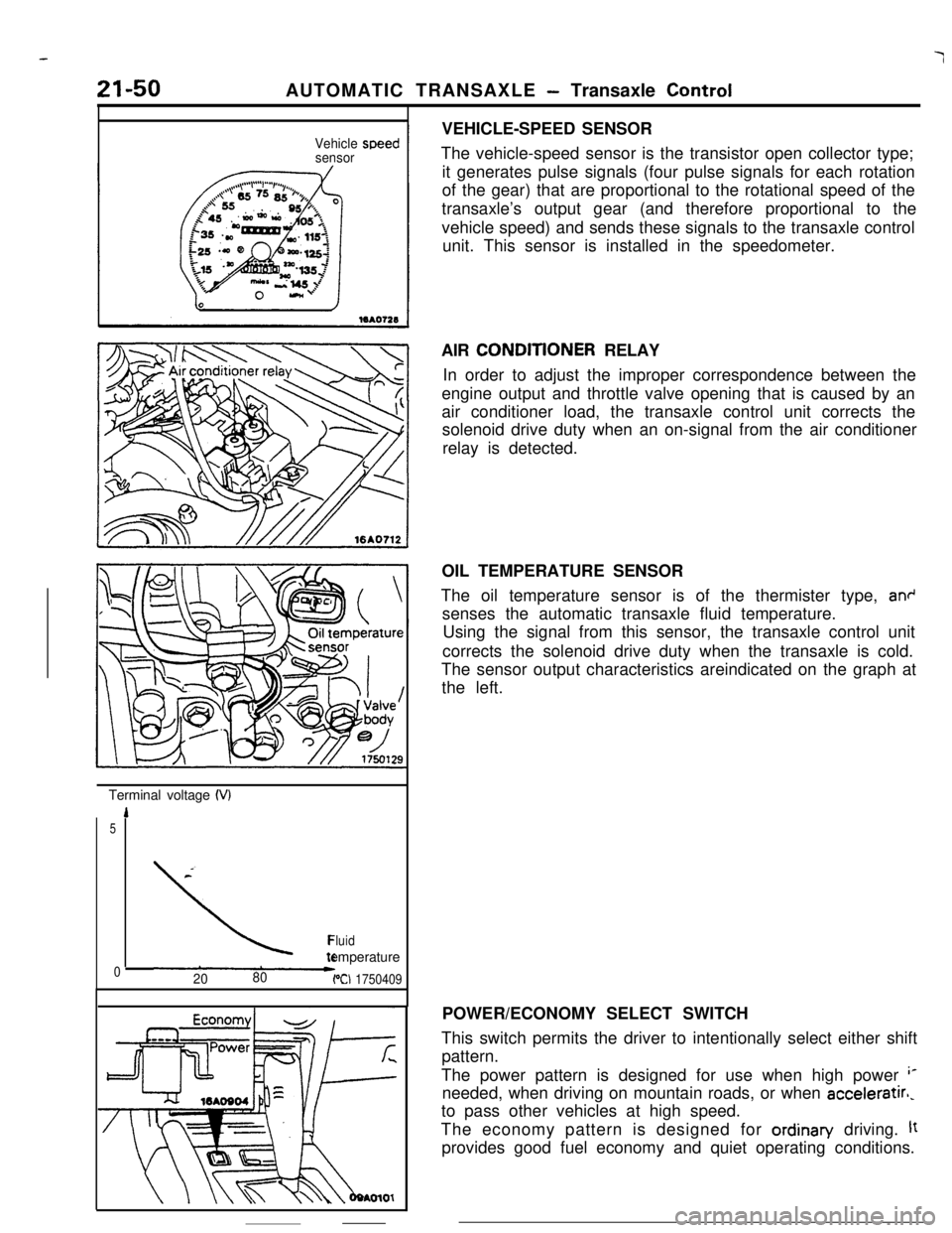
The vehicle-speed sensor is the transistor open collector type;
it generates pulse signals (four pulse signals for each rotation
of the gear) that are proportional to the rotational speed of the
transaxle’s output gear (and therefore proportional to the
vehicle speed) and sends these signals to the transaxle control
unit. This sensor is installed in the speedometer.
AIR CONDlTlONER RELAY
In order to adjust the improper correspondence between the
engine output and throttle valve opening that is caused by an
air conditioner load, the transaxle control unit corrects the
solenoid drive duty when an on-signal from the air conditioner
relay is detected.
OIL TEMPERATURE SENSOR
The oil temperature sensor is of the thermister type,
an+senses the automatic transaxle fluid temperature.
Using the signal from this sensor, the transaxle control unit
corrects the solenoid drive duty when the transaxle is cold.
The sensor output characteristics areindicated on the graph at
the left.
POWER/ECONOMY SELECT SWITCH
This switch permits the driver to intentionally select either shift
pattern.
The power pattern is designed for use when high power
‘*needed, when driving on mountain roads, or when acceleratirl,
to pass other vehicles at high speed.
The economy pattern is designed for ordinan/ driving.
ltprovides good fuel economy and quiet operating conditions.
Page 337 of 391
23-20BODY - Central Door LocksCENTRAL DOOR LOCKS
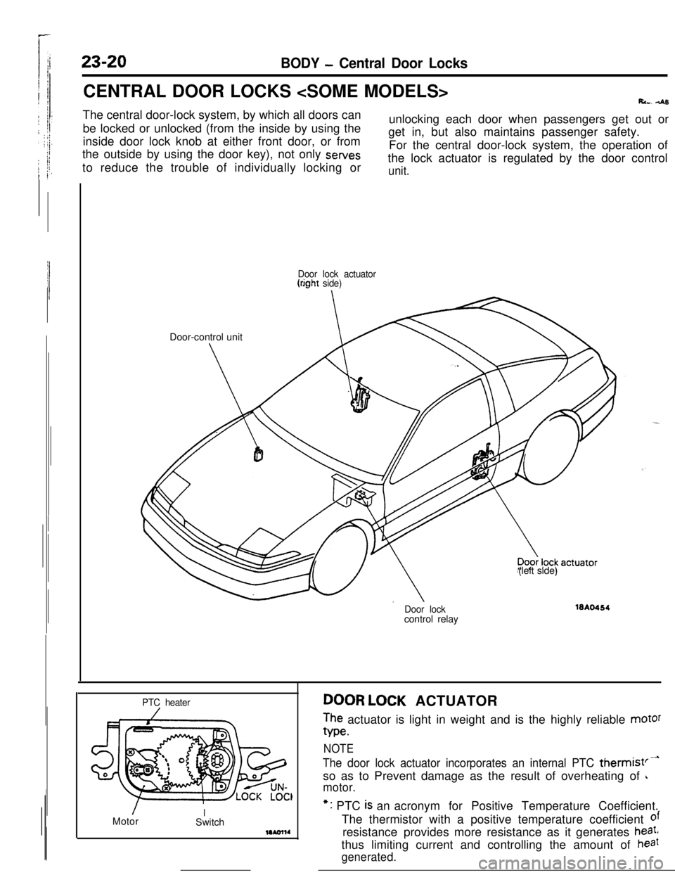
Ri... 4sThe central door-lock system, by which all doors can
be locked or unlocked (from the inside by using the
inside door lock knob at either front door, or from
the outside by using the door key), not only sewes
to reduce the trouble of individually locking orunlocking each door when passengers get out or
get in, but also maintains passenger safety.
For the central door-lock system, the operation of
the lock actuator is regulated by the door control
unit.
Door lock actuator(right side)Door-control unit
(left side)
Door lockcontrol relay16A0464
PTC heater
/MotorISwitchDOOR LOCK ACTUATOR
The actuator is light in weight and is the highly reliable motor
We.
NOTE
The door lock actuator incorporates an internal PTC thermist’-so as to Prevent damage as the result of overheating of
L
motor.*: PTC
is an acronym for Positive Temperature Coefficient.
The thermistor with a positive temperature coefficient
ofresistance provides more resistance as it generates
heat,thus limiting current and controlling the amount of
haat
generated.
Page 338 of 391
BODY - Central Door Locks23-21
IBattery
1IJDoor lock 4Door lockactuator t(left side)actuator
(right side) -Battery
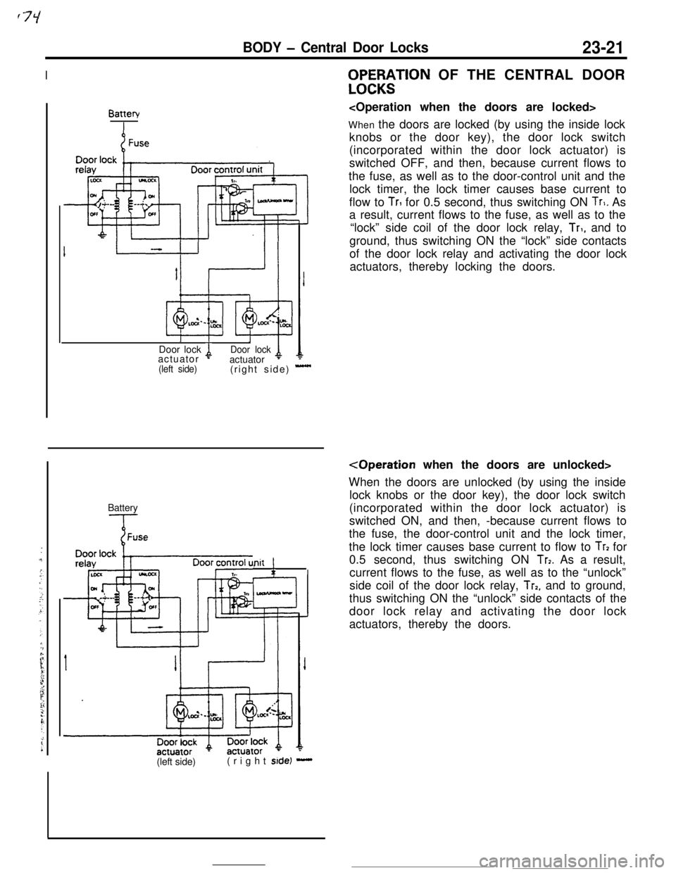
Init !,WF%;$TlON OF THE CENTRAL DOOR
When the doors are locked (by using the inside lock
knobs or the door key), the door lock switch
(incorporated within the door lock actuator) is
switched OFF, and then, because current flows to
the fuse, as well as to the door-control unit and the
lock timer, the lock timer causes base current to
flow to
TrI for 0.5 second, thus switching ON Tr,. As
a result, current flows to the fuse, as well as to the
“lock” side coil of the door lock relay,
Tr,, and to
ground, thus switching ON the “lock” side contacts
of the door lock relay and activating the door lock
actuators, thereby locking the doors.
When the doors are unlocked (by using the inside
lock knobs or the door key), the door lock switch
(incorporated within the door lock actuator) is
switched ON, and then, -because current flows to
the fuse, the door-control unit and the lock timer,
the lock timer causes base current to flow to
Tr? for
0.5 second, thus switching ON
Tr7. As a result,
current flows to the fuse, as well as to the “unlock”
side coil of the door lock relay,
Trp, and to ground,
thus switching ON the “unlock” side contacts of the
door lock relay and activating the door lock
actuators, thereby the doors.
(left side)(right
side) -
Page 348 of 391
BODY - Seat Belts
._-- -
23-31
Shoulder beltI
Lapbelt
IGlove box pad toasty
Knee protector
Guide rail\Fasten switch
\
SEAT BELTSRZ3SBAS
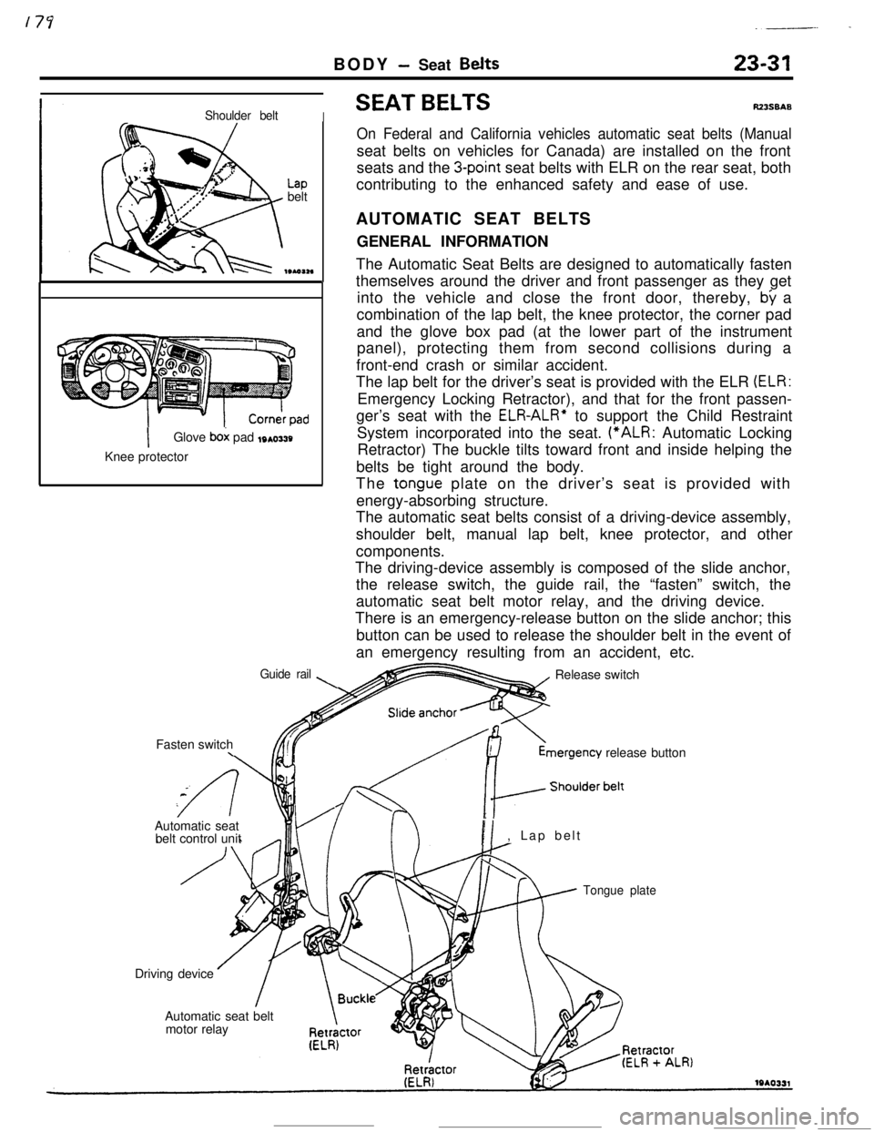
On Federal and California vehicles automatic seat belts (Manualseat belts on vehicles for Canada) are installed on the front
seats and the
3-point seat belts with ELR on the rear seat, both
contributing to the enhanced safety and ease of use.
AUTOMATIC SEAT BELTS
GENERAL INFORMATION
The Automatic Seat Belts are designed to automatically fasten
themselves around the driver and front passenger as they get
into the vehicle and close the front door, thereby,
by a
combination of the lap belt, the knee protector, the corner pad
and the glove box pad (at the lower part of the instrument
panel), protecting them from second collisions during a
front-end crash or similar accident.
The lap belt for the driver’s seat is provided with the ELR
(ELR:Emergency Locking Retractor), and that for the front passen-
ger’s seat with the
ELR-ALR” to support the Child Restraint
System incorporated into the seat. (“ALR: Automatic Locking
Retractor) The buckle tilts toward front and inside helping the
belts be tight around the body.
The
tongue plate on the driver’s seat is provided with
energy-absorbing structure.
The automatic seat belts consist of a driving-device assembly,
shoulder belt, manual lap belt, knee protector, and other
components.
The driving-device assembly is composed of the slide anchor,
the release switch, the guide rail, the “fasten” switch, the
automatic seat belt motor relay, and the driving device.
There is an emergency-release button on the slide anchor; this
button can be used to release the shoulder belt in the event of
an emergency resulting from an accident, etc.
Release switchmergency
release button
Automatic seat
belt control unit
PI, Lap belt
Tongue plateDriving device
Automatic seat belt
motor relay