air filter MITSUBISHI ECLIPSE 1990 Service Manual
[x] Cancel search | Manufacturer: MITSUBISHI, Model Year: 1990, Model line: ECLIPSE, Model: MITSUBISHI ECLIPSE 1990Pages: 391, PDF Size: 15.27 MB
Page 121 of 391
FUEL SYSTEM -Fuel Supply and Fuel Pressure Control14-9
03Poo4:Diaphragm
from intake
4Fuel from delivery pipe
4m
B(42.7)QQ
2
sl -196 2
(26.4) g
t
$!a d
9
0)Positive5 z‘. pressure
(E.2)
w
FUEL FILTERA high-pressure type filter is installed at the delivery end of the
fuel pump.
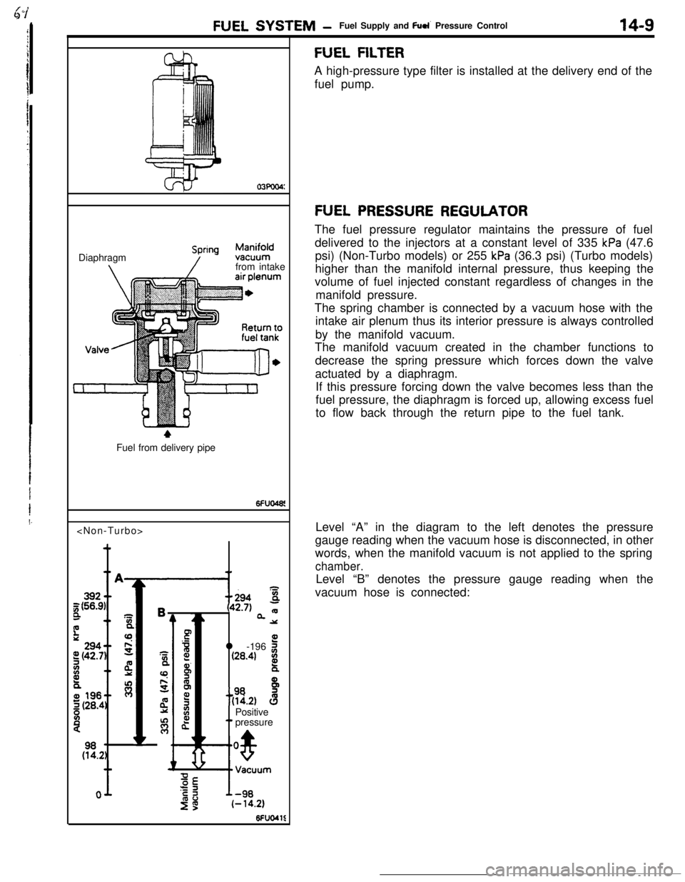
FUEL PRESSURE REGULATORThe fuel pressure regulator maintains the pressure of fuel
delivered to the injectors at a constant level of 335
kPa (47.6
psi) (Non-Turbo models) or 255
kPa (36.3 psi) (Turbo models)
higher than the manifold internal pressure, thus keeping the
volume of fuel injected constant regardless of changes in the
manifold pressure.
The spring chamber is connected by a vacuum hose with the
intake air plenum thus its interior pressure is always controlled
by the manifold vacuum.
The manifold vacuum created in the chamber functions to
decrease the spring pressure which forces down the valve
actuated by a diaphragm.
If this pressure forcing down the valve becomes less than the
fuel pressure, the diaphragm is forced up, allowing excess fuel
to flow back through the return pipe to the fuel tank.
Level “A” in the diagram to the left denotes the pressure
gauge reading when the vacuum hose is disconnected, in other
words, when the manifold vacuum is not applied to the spring
chamber.Level “B” denotes the pressure gauge reading when the
vacuum hose is connected:
Page 141 of 391
FUEL SYSTEM- Engine Control Unit14-29
SFUllSOTerminal
ConnectionTerminalConnectionNo.
No.
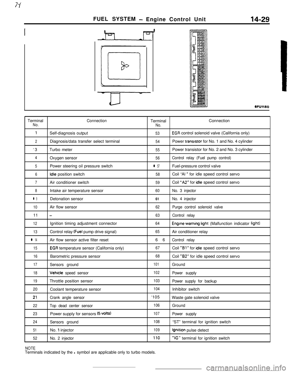
1Self-diagnosis output53EGR control solenoid valve (California only)
2Diagnosis/data transfer select terminal54Power transrstor for No. 1 and No. 4 cylinder
‘3Turbo meter
55Power transistor for No. 2 and No. 3 cylinder
4Oxygen sensor56Control relay (Fuel pump control)
5Power steering oil pressure switchl 57Fuel-pressure control valve
6Idle position switch58Coil “Al ” for idle speed control servo
7Air conditioner switch59Coil “A2” for idle speed control servo
8Intake air temperature sensor60No. 3 injector
l 9Detonation sensor61No. 4 injector
10Air flow sensor62Purge control solenoid valve11
-63Control relay
12Ignition timing adjustment connector64Engine warning irght (Malfunction indicator light)
13Control relay (Fuel pump drive signal)65Air conditioner relay
l 14Air flow sensor active filter reset66Control relay
15EGR temperature sensor (California only)67Coil “Bl ” for idle speed control servo
16Barometric pressure sensor68Coil “B2” for idle speed control servo
17Sensors ground101Ground
18Vehicle speed sensor102Power supply
19Throttle position sensor103Power supply for backup
20Coolant temperature sensor
104Inhibitor switch
21Crank angle sensor‘105
Waste gate solenoid valve
22Top dead center sensor106Ground
23Power supply for sensors (5 volts)107Power supply
24Sensors ground108“ST” terminal for ignition switch
51No. 1 injector109Ignition pulse detect
52No. 2 injector170“IG ” terminal for ignition switch
NOTETerminals indicated by the l symbol are applicable only to turbo models.
Page 146 of 391
-
14-34FUEL SYSTEM - Fuel Injection Control
TDC sensorAir flow sensor
I
Reading of input signal1
I ,,
uOperation mode decisionOperation mode decision data
I rBasic valve opening time data
Enginecontrol unitInjector activation time control
Injector activation pulse generationControl factor data of
engine coolant temperature,
intake air temperature and
barometric pressure, etc.
Injector1
6FUO766Needle valveFilter
Connector
Solenoid coil
Plunger
-4
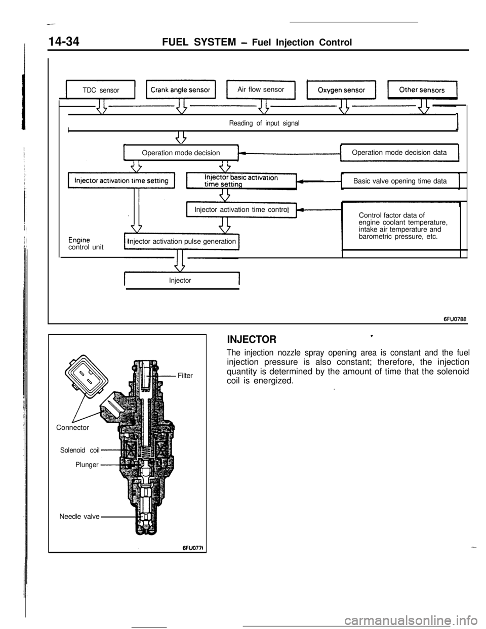
INJECTOR,
The injection nozzle spray opening area is constant and the fuelinjection pressure is also constant; therefore, the injection
quantity is determined by the amount of time that the solenoid
coil is energized.
.
Page 169 of 391
FUEL SYSTEMAir Flow Sensor (AFSI Filter Reset Control
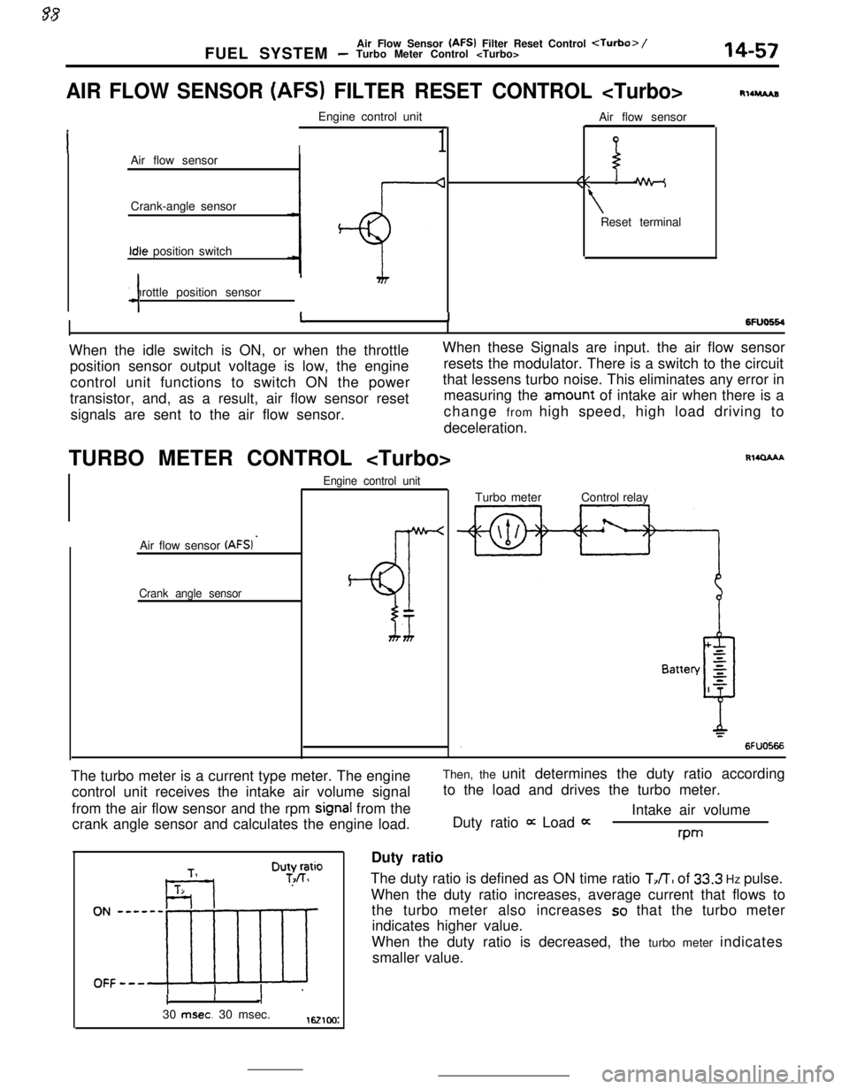
AIR FLOW SENSOR (AFS) FILTER RESET CONTROL
I1Air flow sensor
Crank-angle sensorIdle position switch
Throttle position sensor
4Air flow sensor
//\\ -
\Reset terminal
RllruAs
6FlJo664I11When the idle switch is ON, or when the throttleWhen these Signals are input. the air flow sensor
position sensor output voltage is low, the engineresets the modulator. There is a switch to the circuit
control unit functions to switch ON the powerthat lessens turbo noise. This eliminates any error in
transistor, and, as a result, air flow sensor resetmeasuring the
.amount of intake air when there is a
signals are sent to the air flow sensor.change from high speed, high load driving to
deceleration.
TURBO METER CONTROL
Air flow sensor
(AFSI ’
Crank angle sensorEngine control unit
BT
Rl4QAAATurbo meterControl relay
The turbo meter is a current type meter. The engine
control unit receives the intake air volume signal
from the air flow sensor and the rpm
signal from the
crank angle sensor and calculates the engine load.Then, the unit determines the duty ratio according
to the load and drives the turbo meter.
Intake air volume
Duty ratio
it Load 0:rwDuty ratio
The duty ratio is defined as ON time ratio
TJT, of 33.3 Hz pulse.
When the duty ratio increases, average current that flows to
the turbo meter also increases
so that the turbo meter
indicates higher value.
When the duty ratio is decreased, the turbo meter indicates
smaller value.
cI30
msec. 30 msec.1621cm:
Page 385 of 391
__..--. -._ _^__. __--- -._ _..EMISSION CONTROL SYSTEMS
- Evaporative Emission Control Svsvem25-l 1
,VAPORATlVE EMISSION CON-
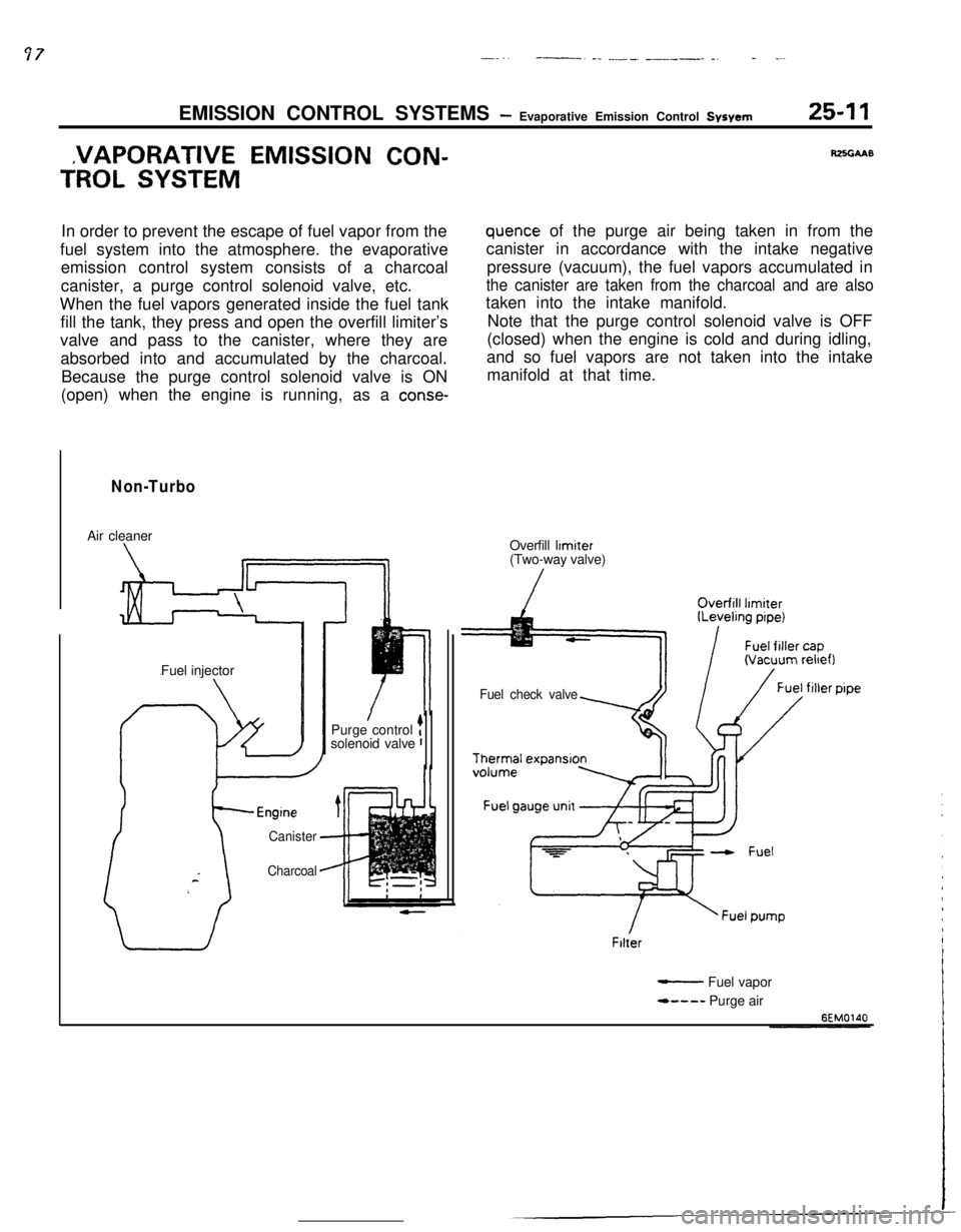
TROL SYSTEMIn order to prevent the escape of fuel vapor from the
fuel system into the atmosphere. the evaporative
emission control system consists of a charcoal
canister, a purge control solenoid valve, etc.
When the fuel vapors generated inside the fuel tank
fill the tank, they press and open the overfill limiter’s
valve and pass to the canister, where they are
absorbed into and accumulated by the charcoal.
Because the purge control solenoid valve is ON
(open) when the engine is running, as a
conse-
Non-TurboAir cleaner
Fuel injector
Canister
Charcoal
/Purge control tsolenoid valve r
RZSGAAB
quence of the purge air being taken in from the
canister in accordance with the intake negative
pressure (vacuum), the fuel vapors accumulated in
the canister are taken from the charcoal and are alsotaken into the intake manifold.
Note that the purge control solenoid valve is OFF
(closed) when the engine is cold and during idling,
and so fuel vapors are not taken into the intake
manifold at that time.
Overfill
limiter(Two-way valve)
Fuel check valveFilter
- Fuel vapor
*---- Purge air
Page 386 of 391
25-12EMISSION CONTROL SYSTEMS- Evaporative Emisson Control System-
TurboPurge control valve
/Air cleaner
Canister
-Charcoal-ITurbo-
chargerPurge control
solenoid valve
Fuel check valve
Thermal expansion
Fuel gauge unit
Filter
- Fuel vapor
- - - - Purge air
BEMO211
%-E?”solenoidvalve
Charcoal -fuel tank
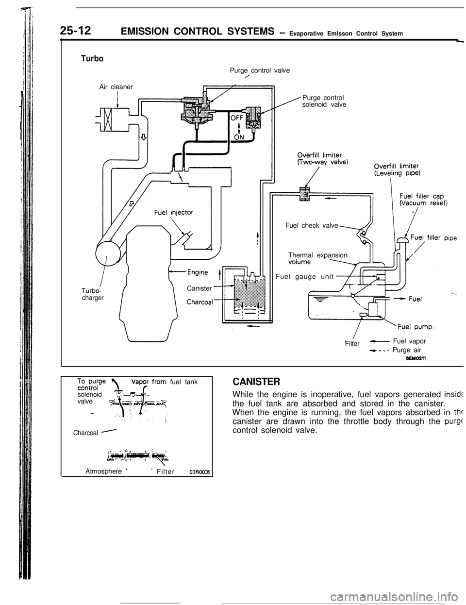
CANISTERWhile the engine is inoperative, fuel vapors generated
insidEthe fuel tank are absorbed and stored in the canister.
When the engine is running, the fuel vapors absorbed in
thfcanister are drawn into the throttle body through the
purgecontrol solenoid valve.
Atmosphere
L- Filter03Roo3E