turn signal MITSUBISHI ECLIPSE 1990 Service Manual
[x] Cancel search | Manufacturer: MITSUBISHI, Model Year: 1990, Model line: ECLIPSE, Model: MITSUBISHI ECLIPSE 1990Pages: 391, PDF Size: 15.27 MB
Page 55 of 391
ELECTRICAL - Fuses8-3q
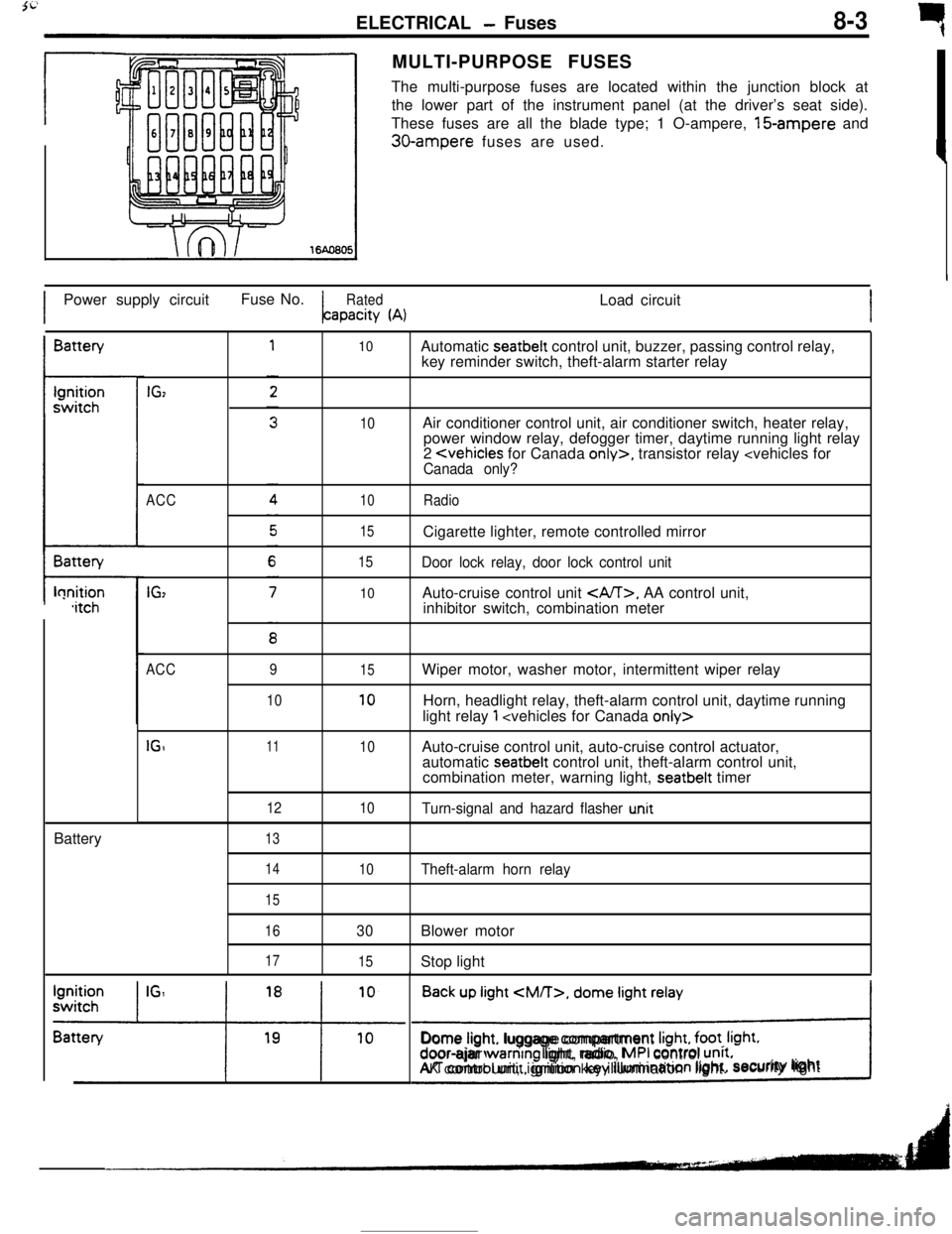
rMULTI-PURPOSE FUSES
The multi-purpose fuses are located within the junction block at
the lower part of the instrument panel (at the driver’s seat side).
These fuses are all the blade type; 1 O-ampere, 15-ampere and
30-ampere fuses are used.
IPower supply circuitFuse No.
RatedLoad circuitapacity
(A)IBattery
t-lonition,itchBattery
IGz
ACC
IG,
10
10
10
15
15
10Automatic seatbelt control unit, buzzer, passing control relay,
key reminder switch, theft-alarm starter relay
Air conditioner control unit, air conditioner switch, heater relay,
power window relay, defogger timer, daytime running light relay
2
Door lock relay, door lock control unitAuto-cruise control unit
, AA control unit,
inhibitor switch, combination meter
ACC
IGI9
1011
12
1315
10
10
10Wiper motor, washer motor, intermittent wiper relay
Horn, headlight relay, theft-alarm control unit, daytime running
light relay
1
automatic seatbelt control unit, theft-alarm control unit,
combination meter, warning light, seatbelt timer
Turn-signal and hazard flasher u.nit
14
15
16
17
10Theft-alarm horn relay
30Blower motor
15Stop light
Back up light
CM/T>, dome light relay
!Dome light. luggage compartment
Irght, foot. Irght.door-ajar warntng light, radio, MPI control unrt.AK control unit, ignition key illumination light.security lightI
Page 65 of 391
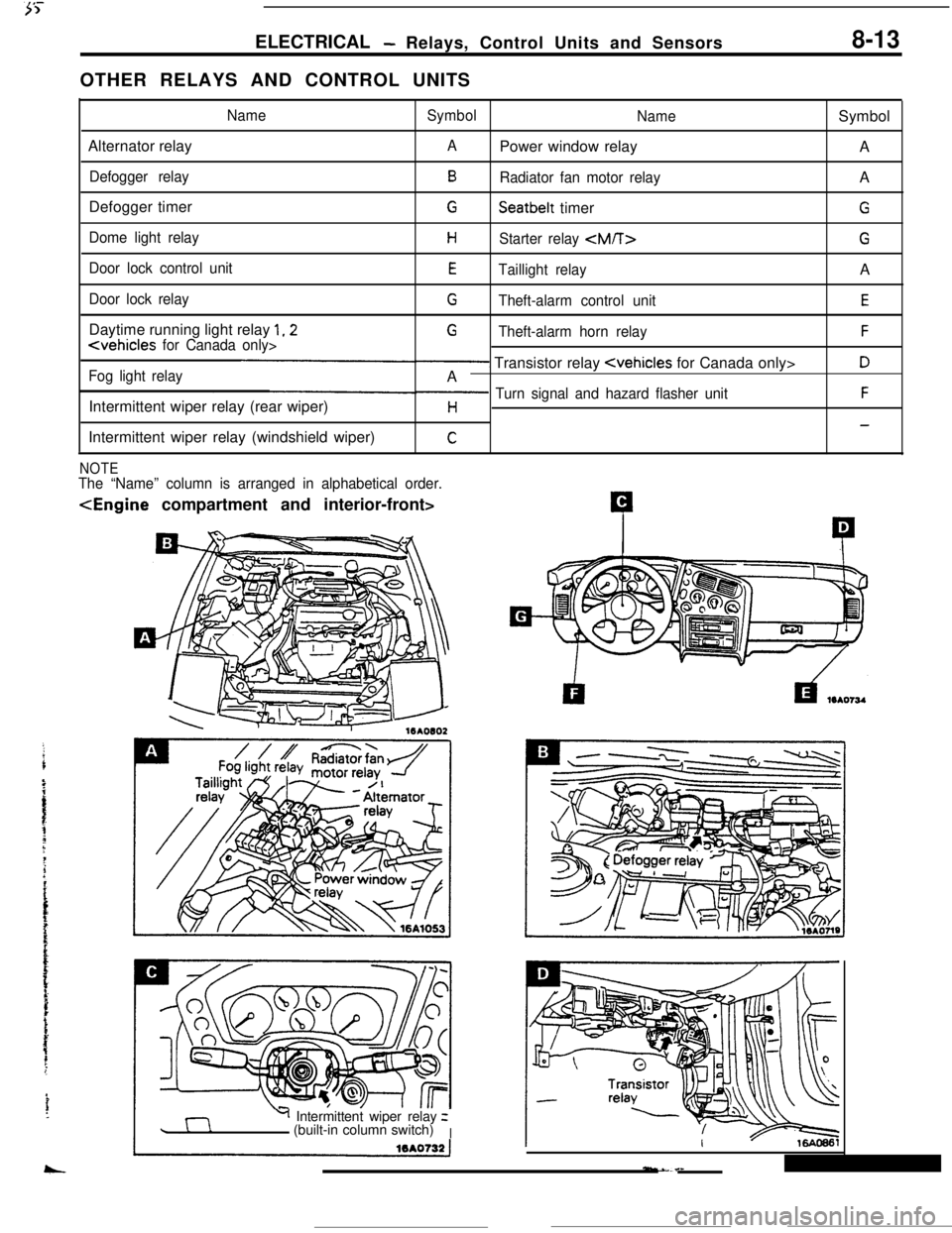
ELECTRICAL- Relays, Control Units and Sensors8-13OTHER RELAYS AND CONTROL UNITS
NameSymbol
NameSymbol
Alternator relay
APower window relay
A
Defogger relayBRadiator fan motor relayA
Defogger timer
GSeatbelt timerG
Dome light relayHStarter relay
Door lock control unitETaillight relayA
Door lock relayGTheft-alarm control unitEDaytime running light relay
1,2G
Fog light relay- Transistor relay
Intermittent wiper relay (rear wiper)
p Turn signal and hazard flasher unitFH-Intermittent wiper relay (windshield wiper)
C
NOTEThe “Name” column is arranged in alphabetical order.
Y Intermittent wiper relayz
(built-in column switch)
I
Page 69 of 391
ELECTRICAL - Lighting8-17
Front turnsignal light
(Optical horn)
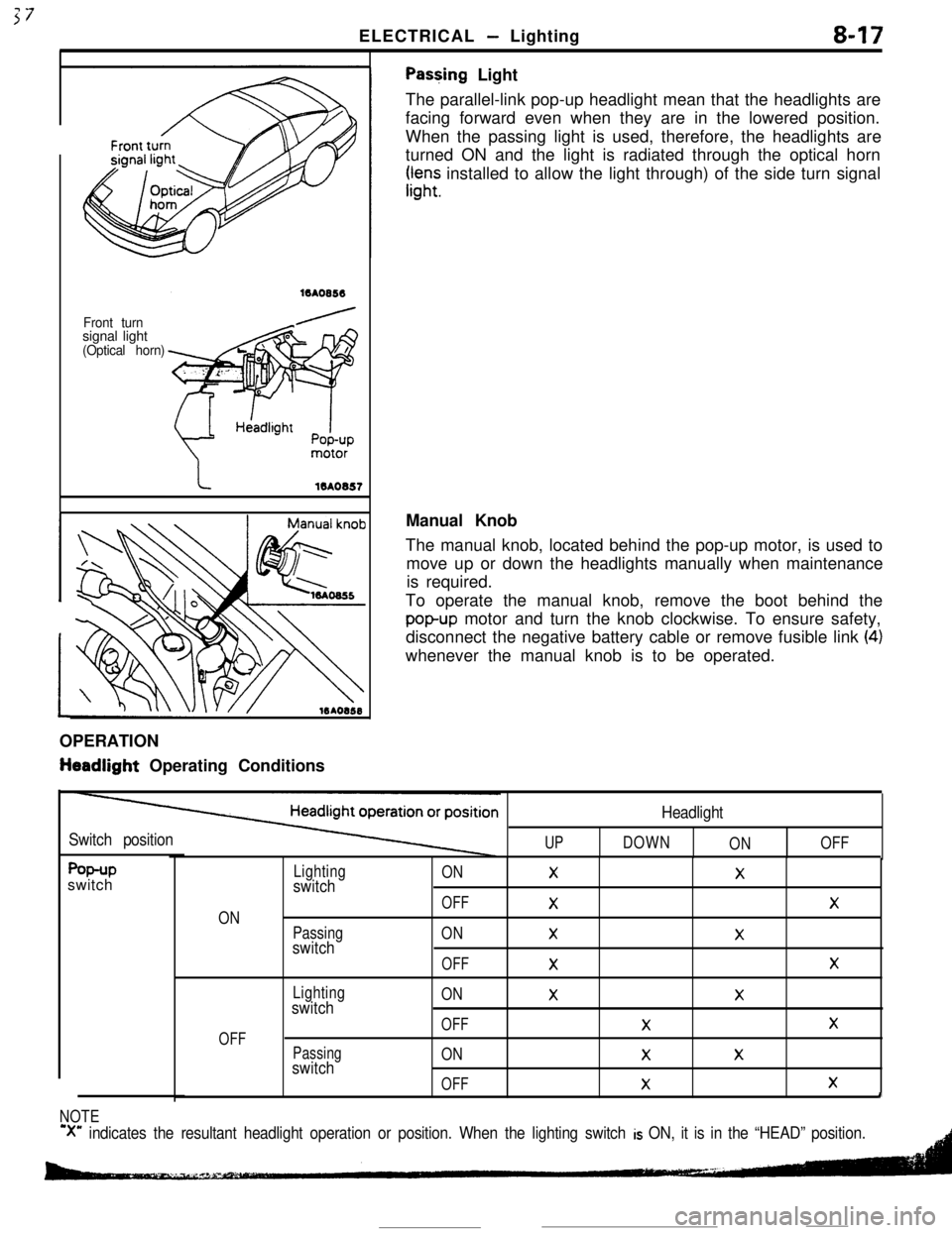
Pas+ing Light
The parallel-link pop-up headlight mean that the headlights are
facing forward even when they are in the lowered position.
When the passing light is used, therefore, the headlights are
turned ON and the light is radiated through the optical horn
rr,“;; installed to allow the light through) of the side turn signal
OPERATION
tieadlight Operating ConditionsManual Knob
The manual knob, located behind the pop-up motor, is used to
move up or down the headlights manually when maintenance
is required.
To operate the manual knob, remove the boot behind the
popup motor and turn the knob clockwise. To ensure safety,
disconnect the negative battery cable or remove fusible link
(4)whenever the manual knob is to be operated.
Switch positionUP
Headlight
DOWN
ONOFF
f%+Pswitch
ON
OFF
Lightingswitch
Passingswitch
Lightingswitch
Passingswitch
ONXX
OFF
XX
ONXX
OFF
XX
ONXX
OFFXX
ONXX
OFF
XXI
NOTE
‘X” indicates the resultant headlight operation or position. When the lighting switch is ON, it is in the “HEAD” position.
Page 78 of 391
8-26ELECTRICAL - Engine Electrical
No.:
4Signal unit for
, tachometer
71
x
No. 3
6EL0025
Capa &orCylinderNo. mark
6EL0057
To No. 1spark plug
To No. 4
spark plug
To No. 3spark plug
To No. 2spark plug
6EL005t
OC,IB, G
OC, IB, G IB, OC:IGNITION COIL
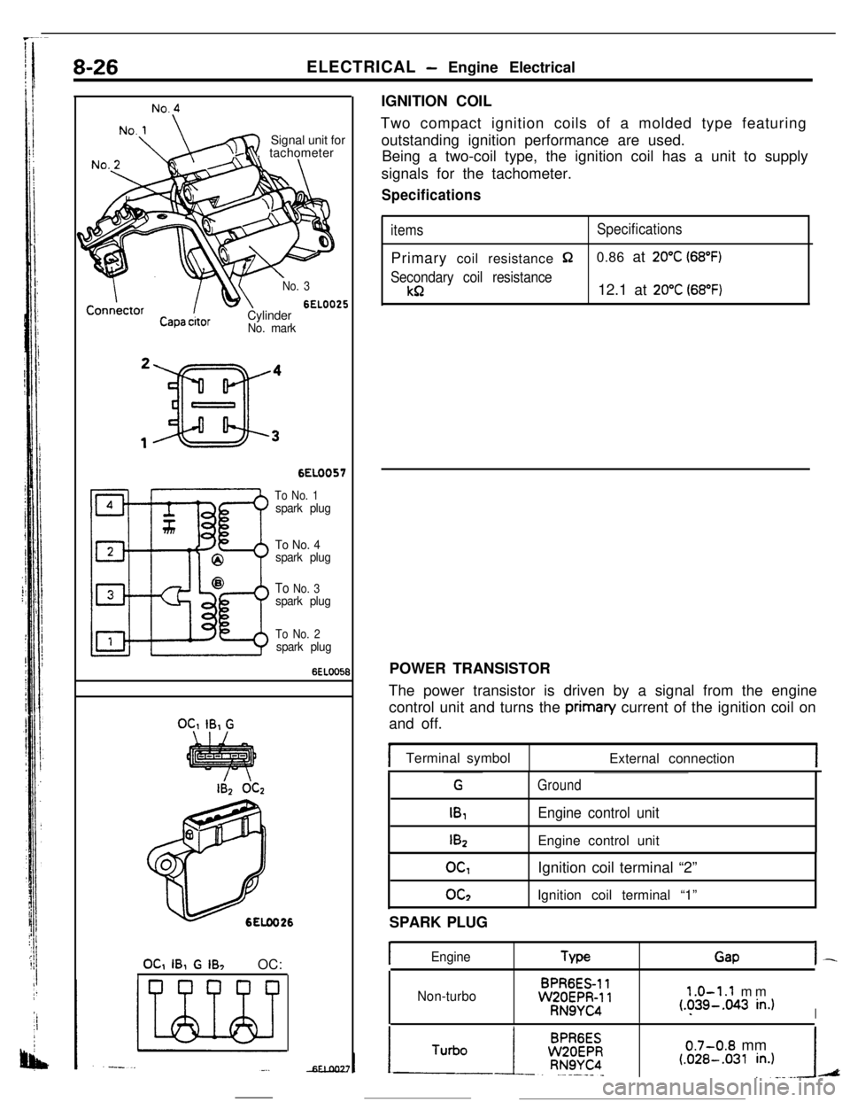
Two compact ignition coils of a molded type featuring
outstanding ignition performance are used.
Being a two-coil type, the ignition coil has a unit to supply
signals for the tachometer.
Specifications
itemsSpecificationsPrimary coil resistance
$20.86 at 20°C (68°F)
Secondary coil resistance
kR12.1 at 20°C (68°F)POWER TRANSISTOR
The power transistor is driven by a signal from the engine
control unit and turns the priman/ current of the ignition coil on
and off.
Terminal symbol
External connection
G
IB,
I&
Ground
Engine control unitEngine control unit
OGoc2Ignition coil terminal “2”
Ignition coil terminal “1”
SPARK PLUG
IEngineTypeGapI-
Non-turboBPR6ES-11WZOEPR-11RN9YC4
1.0-1.1 mm(.?39-.043 in.)I
0.7-0.8 mm(.OZB-.031 in.)A
Page 80 of 391
8-28ELECTRICAL- Engine Electrical
IGNITION TIMING CONTROL
Reading of Input signallgnitlon power
distribution control
(selection of power
transistor actlvatlon)Control mode
I II II IControl mode
dectsion data
Basic energlzatlon
I’
Engine control unitPower
Powertranststor “A”tranststor “B”
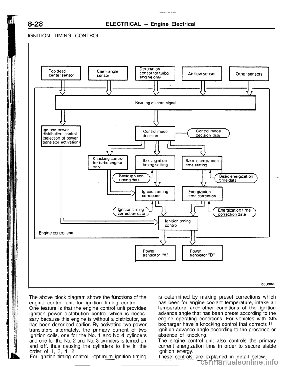
6ELOO66The above block diagram shows the
fljnctions of the
engine control unit for ignition timing control.
One feature is that the engine control unit provides
ignition power distribution control which is neces-
sary because this engine is without a distributor, as
has been described earlier. By activating two power
transistors alternately, the primary current of two
ignition coils, one for the No. 1 and No.4 cylinders
and one for the No. 2 and No, 3 cylinders is turned onand
off. thus causing the cylinders to fire in the
order of 1, 3, 4, 2.
For ignition timing control, -optimum ignition timing.^--_
_. -.is determined by making preset corrections which
has been for engine coolant temperature, intake air
temperature an& other conditions of the ignition
advance angle that has been preset according to the
engine operating conditions. For vehicles with
tur=_.bocharger have a knocking control that corrects tl
ignition advance angle according to the presence or
absence of knocking.
The engine control unit also controls the primary
current energization time in order to secure stable
ignition energy.
These controls are explained in detail below.
--. .----- ---- --- ___. .-. ___.,.__
Page 81 of 391
. ,-s- ,-T,“~:~y.“‘~...:tg==ELECTRICAL
-Engine Electrical8-29Ignition Power Distribution Control
No. 1 TDC
I
No. 3 TDCNo 4TDCNo 2 TDC
‘op dead center signal,\
I1IIII
Crank angle signal
No. 1 cylinderCombustionExhaustIntakeCompres-
strokestrokestrokeslon stroke
IntakeCompression
t\
CombustionExhaust
No. 3 cyltnderstrokestroke. strokestroke
No. 4 cylinder, t\
IntakeCompressionstrokestroker$,mkbeustlonExhauststroke
Combus-No. 2 cylinder tlon
strokeintake
strokeCompresslon
stroke6EL0067
75”BTDC TI
Crank 1
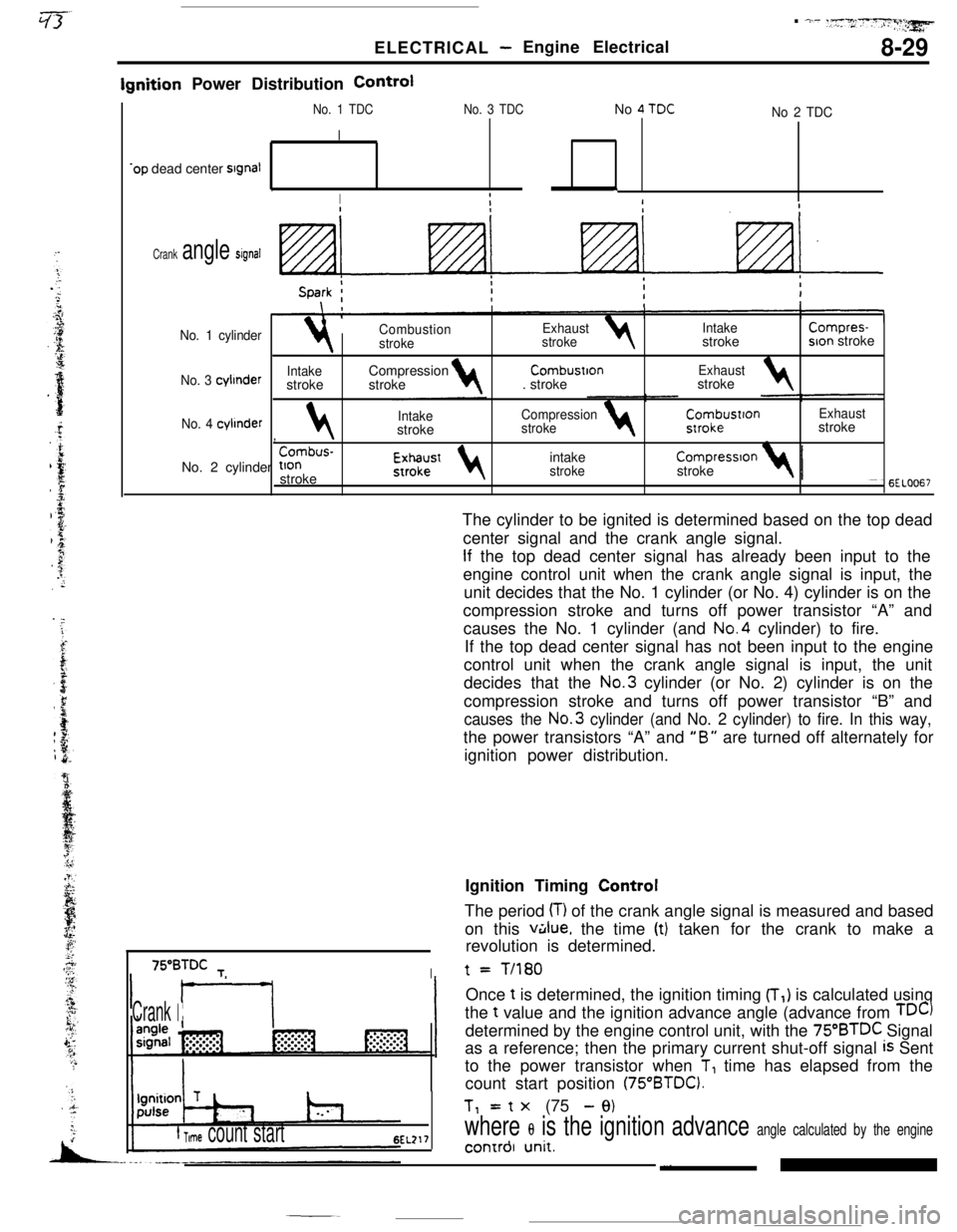
f Time count start6EL217The cylinder to be ignited is determined based on the top dead
center signal and the crank angle signal.
If the top dead center signal has already been input to the
engine control unit when the crank angle signal is input, the
unit decides that the No. 1 cylinder (or No. 4) cylinder is on the
compression stroke and turns off power transistor “A” and
causes the No. 1 cylinder (and No.4 cylinder) to fire.
If the top dead center signal has not been input to the engine
control unit when the crank angle signal is input, the unit
decides that the No.3 cylinder (or No. 2) cylinder is on the
compression stroke and turns off power transistor “B” and
causes the No.3 cylinder (and No. 2 cylinder) to fire. In this way,the power transistors “A” and
“B” are turned off alternately for
ignition power distribution.t
= T/180Once
t is determined, the ignition timing (T,) is calculated using
the t value and the ignition advance angle (advance from
TDC)determined by the engine control unit, with the
75”BTDC Signal
as a reference; then the primary current shut-off signal
is Sent
to the power transistor when
T, time has elapsed from the
count start position
(75“BTDC).Tl= t
x (75 - 9)
where 8 is the ignition advance angle calculated by the engine_, ~4 -‘*Lonrrol unlr.Ignition Timing Control
The period
(T) of the crank angle signal is measured and based
on this
v&lue, the time (t) taken for the crank to make a
revolution is determined.
Page 82 of 391
8-30ELECTRICAL - Engine Electrical
Ignition Advance Angle Control
While
cranking
Fixed angle(5”BTD.C)Engme coolantBarometnc‘-Intake air 1temperaturepressuretemperaturesensorsensor, sensor
Dunng normal operatlon4i+
Advance angle map valueEngine
coolantBarometricIntake airaccording to engine speed4and intake air volumetemperature- pressure__c temperature 4
correctioncorrectloncorrectton
Durtng ignition tlmmg adjustment
Fixed angle(5”BTDC)
c
=ower transistor
-$To ignition
coil
s
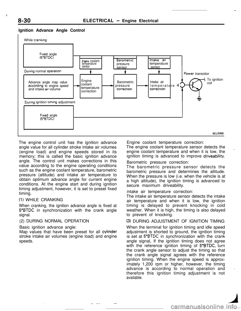
6EL0066The engine control unit has the ignition advance
angle value for all cylinder stroke intake air volumes
(engine load) and engine speeds stored in its
memory; this is called the basic ignition advance
angle. The control unit makes corrections in this
value according to the engine operating conditions
such as the engine coolant temperature, barometric
pressure (altitude) and intake air temperature to
obtain optimum advance angle for current engine
conditions. At the engine start and during ignition
timing adjustment, however, it is set to preset fixed
timing.
(1) WHILE CRANKING
When cranking, the ignition advance angle is fixed at
5”BTDC in synchronization with the crank angle
signal.(2) DURING NORMAL OPERATION
Basic ignition advance angle:
Map values that have been preset for all cylinder
stroke intake air volumes (engine load) and engine
speeds.Engine coolant temperature correction:
The engine coolant temperature sensor detects the
engine coolant temperature and when it is low, the
-ignition timing is advanced to improve driveability.
Barometric pressure correction:
The barometric pressure sensor detects the
barometric pressure and determines the altitude.
When the pressure is low (i.e. when the vehicle is at
a high altitude), the ignition timing is advanced to
secure maximum driveability.
intake air temperature correction:
The intake air temperature sensor detects the intake
air temperature and when it is low, the ignition
timing is delayed to prevent knocking in cold
weather. When it is high, the timing is also delayed
to prevent of knocking.
(3) DURING ADJUSTMENT OF IGNITION TIMING
When the terminal for ignition timing and idle speed
adjustment is shorted to ground, the ignition timing
is set at
5”BTDC in synchronization with the crank
angle signal, If the ignition timing does not agree
with the reference ignition timing of 5’BTDC, turn
the crank angle sensor to adjust the timing so that
the crank angle signal agrees with the reference
ignition timing. When the engine speed is approx-
imately 1,200 rpm or higher, however, the timing
advance is according to normal operation and
therefore this ignition timing adjustment is not
available.
-
. .1-_ .---
Page 115 of 391
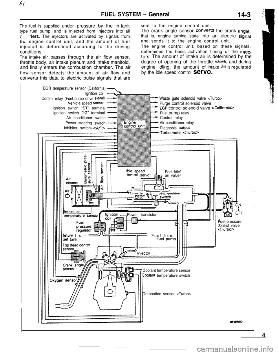
FUEL SYSTEM - General14-3The fuel is supplied under pressure by the in-tanksent to the engine control unit.
type fuel pump, and is injected from injectors into allThe crank angle sensor converts the crank
angle,
cders. The injectors are activated by signals fromthat is, engine turning state into an electric signal
tk, engine control unit, and the amount of fueland sends it to the engine control unit.
injected is determined according to the drivingThe engine control unit, based on these signals,
conditions.determines the basic activation timing of the
injec-The intake air passes through the air flow sensor,
tars. The amount of intake air is determined by the
throttle body, air intake plenum and intake manifold,degree of opening of the throttle
valye,, and during
and finally enters the combustion chamber. The airengine idling, the amount of intake
arr IS regulated
flow sensor detects the amount of air flow and
by the idle speed control servo.converts this data to electric pulse signals that are
EGR temperature sensor (California) 7
Waste gate solenoid valve
Purge control solenoid valve
EGR control solenoid valve
Control relay
Air conditioner relay
Diagnosis output
Ignition coil
Control relay (Fuel pump drive
signal)Vehicle speed
SensorIgnition switch “ST” terminal
Ignition switch
‘IG” terminal
Air conditioner switch
Power steering
switch
Inhibitor switch
Idle speed
ontrol servoFast idle
air valve
-Throttle
&r -kilo m-i&inn’Power transistorleturn to-
uel tank- Fuel from
Coolant temperature sensor
Coolant temperature switchFuel-pressure
control valve
4
Page 135 of 391
‘7JFUEL SYSTEM
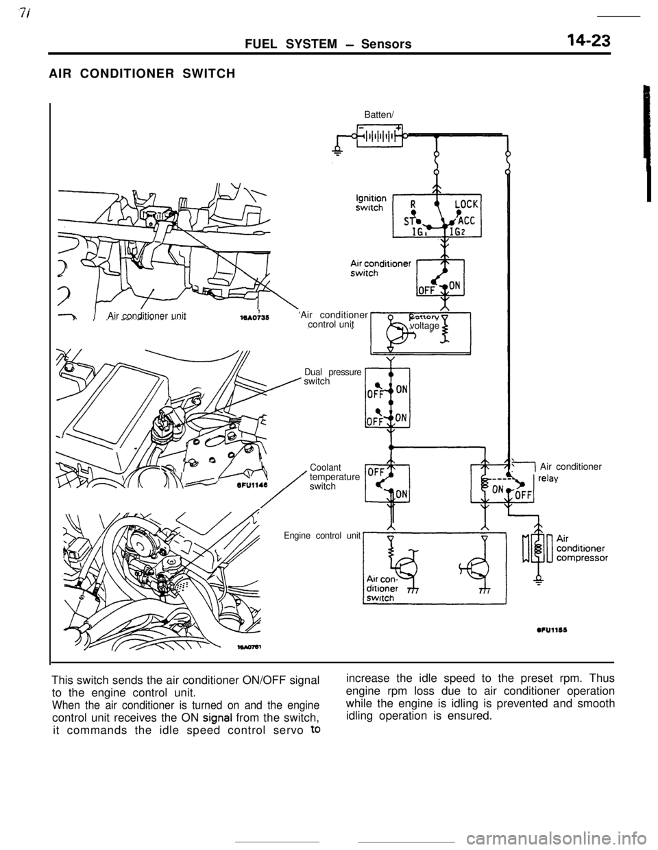
- Sensors14-23AIR CONDITIONER SWITCH
Batten/
-31 .,Air conditioner unitlSAO735‘Air conditioner
control unitI”.._. ,voltage
Dual pressureswitch
-f@ -//Q.j
/
Coolanttemperature6FU1148
switch
Engine control unit
3Air conditioner
This switch sends the air conditioner ON/OFF signal
to the engine control unit.
When the air conditioner is turned on and the enginecontrol unit receives the ON
signal from the switch,
it commands the idle speed control servo
toincrease the idle speed to the preset rpm. Thus
engine rpm loss due to air conditioner operation
while the engine is idling is prevented and smooth
idling operation is ensured.
Page 136 of 391
--
,
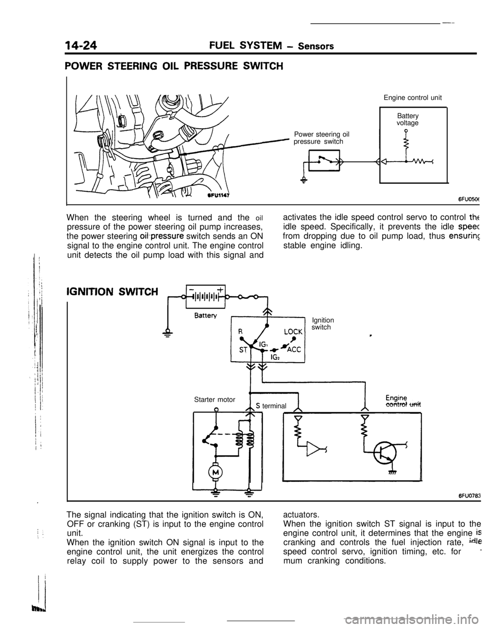
14-24FUEL SYSTEM - Sensors
POWER STEERING OIL PRESSURE SWITCHEngine control unit
Power steering oil
pressure switchBattery
voltage
6FUO5OtIWhen the steering wheel is turned and the oil
pressure of the power steering oil pump increases,
the power steering oifpressure switch sends an ON
signal to the engine control unit. The engine control
unit detects the oil pump load with this signal andactivates the idle speed control servo to control
theidle speed. Specifically, it prevents the idle
speecfrom dropping due to oil pump load, thus
ensuringstable engine idling.IGNITION
SWITCH
1IBattery
Ignition
switch
Starter motor
aS terminalcontrol unit
6FUO762The signal indicating that the ignition switch is ON,
OFF or cranking (ST) is input to the engine control
unit.
When the ignition switch ON signal is input to the
engine control unit, the unit energizes the control
relay coil to supply power to the sensors and
actuators.When the ignition switch ST signal is input to the
engine control unit, it determines that the engine
iscranking and controls the fuel injection rate,
despeed control servo, ignition timing, etc. for
-mum cranking conditions.