turn signal MITSUBISHI ECLIPSE 1990 User Guide
[x] Cancel search | Manufacturer: MITSUBISHI, Model Year: 1990, Model line: ECLIPSE, Model: MITSUBISHI ECLIPSE 1990Pages: 391, PDF Size: 15.27 MB
Page 142 of 391
14-30SELF-DIAGNOSISFUEL SYSTEM- Engine Control Unit
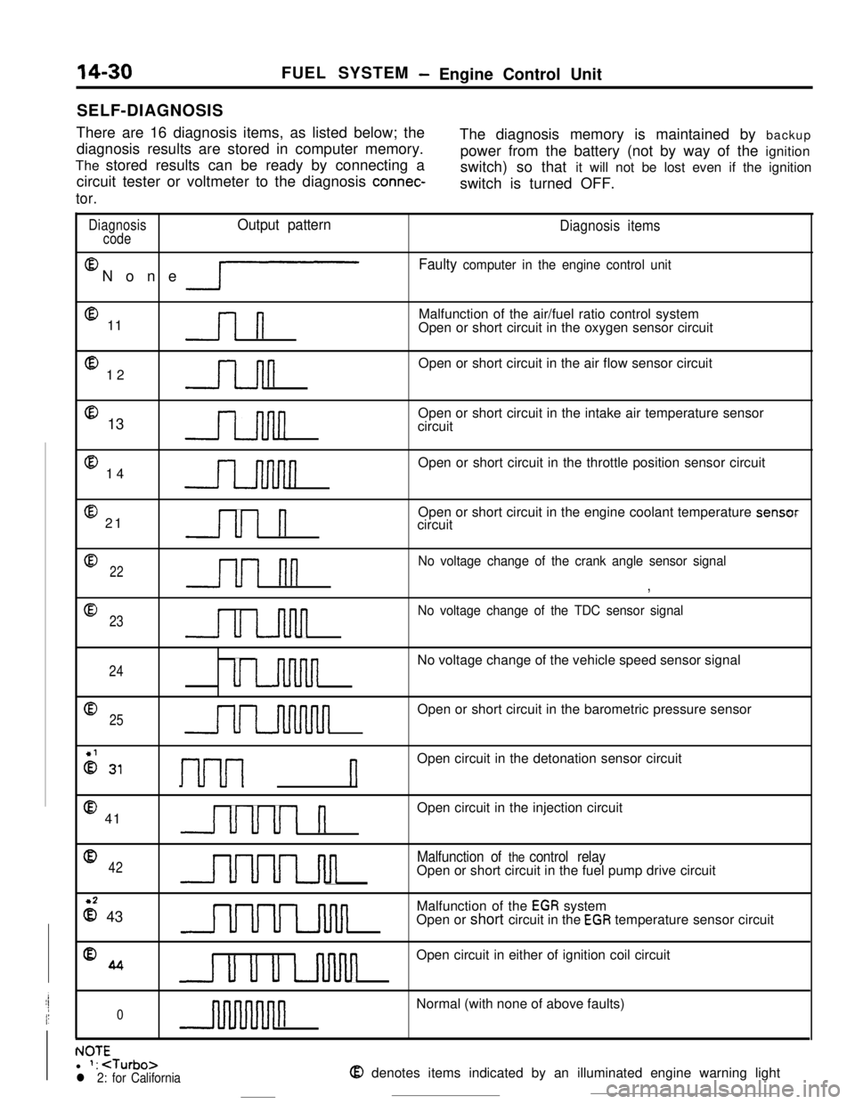
There are 16 diagnosis items, as listed below; the
diagnosis results are stored in computer memory.The diagnosis memory is maintained by backup
The stored results can be ready by connecting apower from the battery (not by way of the ignition
circuit tester or voltmeter to the diagnosis
connec-switch) so that it will not be lost even if the ignition
switch is turned OFF.
tor.
DiagnosisOutput pattern
codeEl
None
lP
@ 11l-l
@ 12n@ 13
@ 14
@ 21Ul n
Diagnosis items
Faulty computer in the engine control unitMalfunction of the air/fuel ratio control system
Open or short circuit in the oxygen sensor circuit
Open or short circuit in the air flow sensor circuit
Open or short circuit in the intake air temperature sensor
circuit
Open or short circuit in the throttle position sensor circuit
Open or short circuit in the engine coolant temperature sensor
circuit
022u1 nn
No voltage change of the crank angle sensor signal
,
@
23
u u-inn
No voltage change of the TDC sensor signal
24uu-uvinnnnNo voltage change of the vehicle speed sensor signal
Q25uuuuuunnnnnOpen or short circuit in the barometric pressure sensor
2 31I-~-~---~ nOpen circuit in the detonation sensor circuit
@ 41uuul nOpen circuit in the injection circuit
042UUuLJul
Malfunction of the control relayOpen or short circuit in the fuel pump drive circuit
z 43UUULnlulMalfunction of the
EGR system
Open or short circuit in the EGR temperature sensor circuit
%4u u u uvinnOpen circuit in either of ignition coil circuit
0nNormal (with none of above faults)
. IA-r-NUltl 1:
Page 147 of 391

FUEL SYSTEM- Fuel Injection Control14-35INJECTOR CIRCUIT
,Battew
Control relay
Resistor
No.Injector
Engine control unit
6FU0516Electricity from the battery flows to the control relay
and then to the resistor (turbocharger-equipped
models only), the injector, and the engine control
unit.Upon reception of the fuel injection signal, theengine control unit causes the power transistor to
be turned ON, thus completing the injector ground
circuit. In this situation, current flows to the injector,
which injects fuel while the power transistor is ON.
Page 158 of 391
.
14-46FUEL SYSTEM- Idle Speed Control
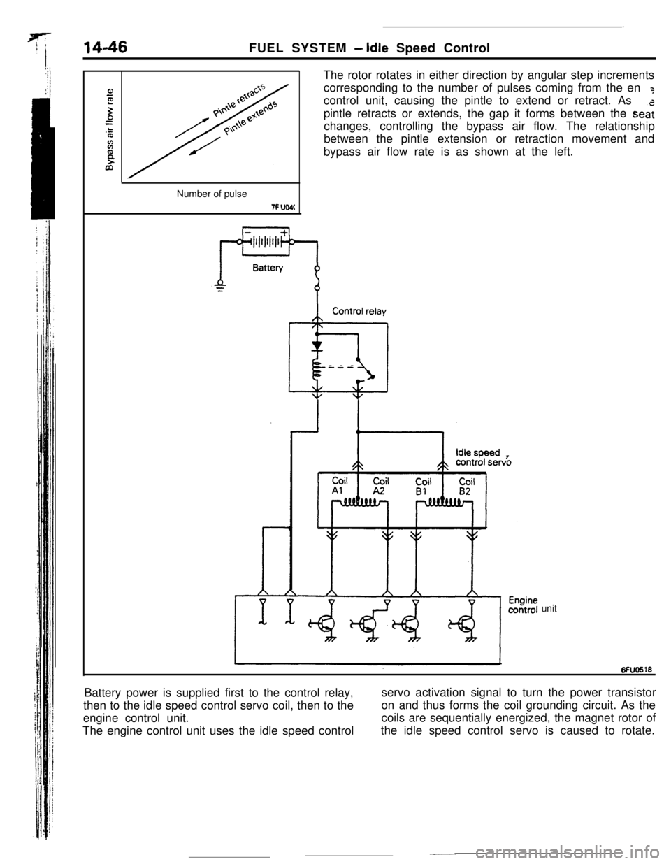
The rotor rotates in either direction by angular step increments
corresponding to the number of pulses coming from the en
?control unit, causing the pintle to extend or retract. As
pintle retracts or extends, the gap it forms between the
sea:changes, controlling the bypass air flow. The relationship
between the pintle extension or retraction movement and
bypass air flow rate is as shown at the left.
Number of pulse
7F UW(Control relay
@iI---
unit
Battery power is supplied first to the control relay,
then to the idle speed control servo coil, then to theservo activation signal to turn the power transistor
engine control unit.on and thus forms the coil grounding circuit. As the
The engine control unit uses the idle speed controlcoils are sequentially energized, the magnet rotor of
the idle speed control servo is caused to rotate.
Page 162 of 391
14-50FUEL SYSTEM- Idle Speed Control
SDeed adiustina screwI -Throttle valve
Lw-3O(-22) 0132) 30(86! 601140) 9ofl94)Coolant temperature
“C (OF)6FUO641
E94
72--2--I
Q--.-.-z
3201.000 --4-\-\
5P9.o%IIIaI L-2O(-41 Of3214Of104)801176)Coolant temperature
“C VF)6FU028E
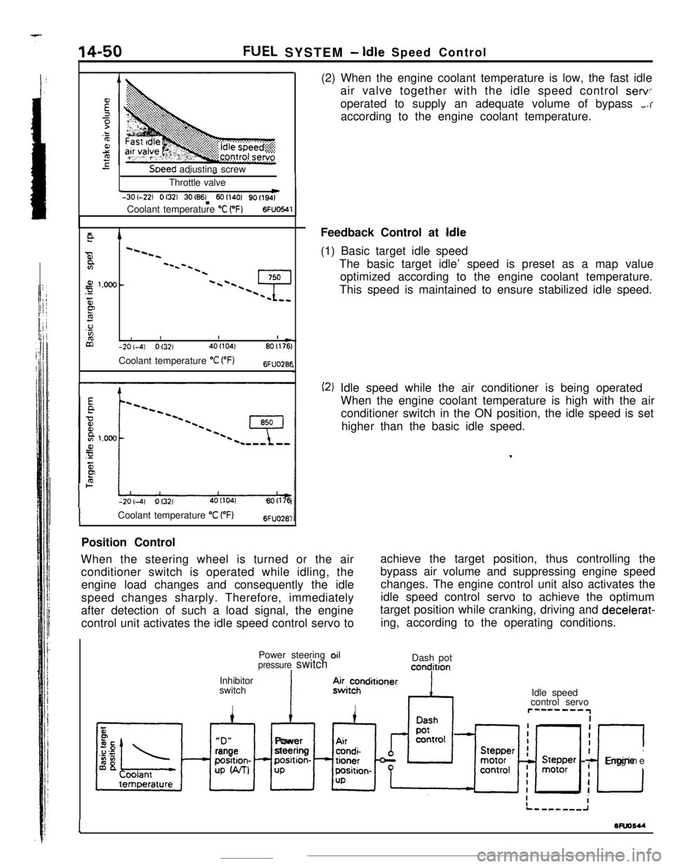
-201-4) Of3214OI104180(176(2) When the engine coolant temperature is low, the fast idle
air valve together with the idle speed control
servoperated to supply an adequate volume of bypass
,.raccording to the engine coolant temperature.
Feedback Control at
Idle(1) Basic target idle speed
The basic target idle’ speed is preset as a map value
optimized according to the engine coolant temperature.
This speed is maintained to ensure stabilized idle speed.
(2) Idle speed while the air conditioner is being operated
When the engine coolant temperature is high with the air
conditioner switch in the ON position, the idle speed is set
higher than the basic idle speed.
,
ICoolant temperature “C VF)6FUO28:Position Control
When the steering wheel is turned or the air
conditioner switch is operated while idling, theachieve the target position, thus controlling the
engine load changes and consequently the idlebypass air volume and suppressing engine speed
changes. The engine control unit also activates the
speed changes sharply. Therefore, immediately
after detection of such a load signal, the engine
control unit activates the idle speed control servo toidle speed control servo to achieve the optimum
target position while cranking, driving and decelerat-
ing, according to the operating conditions.
Power steering oil
pressure switchIInhibitor
switch
IDash pot
concjition“D”
xl
rangeposition-
UP W-U
IAlPower
steeringposition-
UP.4~i~hnditioner
IIdle speed
control servor”--““IiiI
I
c
IEngine
I
I
1wuosu
-
Page 166 of 391
FUEL SYSTEM- Power Supply Control
Battery
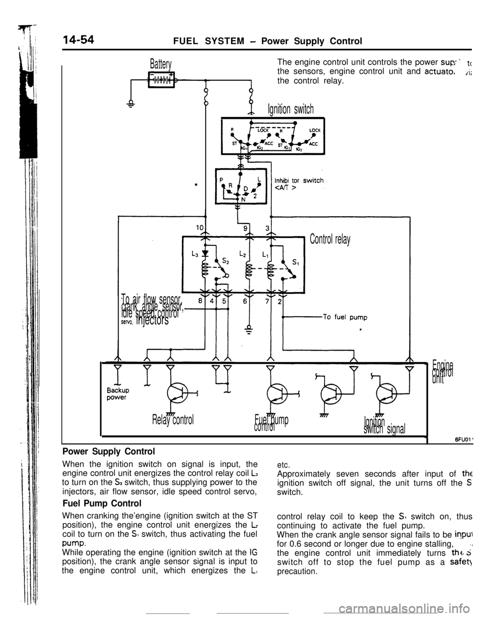
L11The engine control unit controls the power
suv ’tcthe sensors, engine control unit and
actuate,A;the control relay.
-P
.
-p.Ignition switch
Inn yr
To air flow sensor,crank angle sensor,idle speed controlsetvo. injectors
Control relay
Relay controlFuel pump
controlIgnitionswitch signal
Enginecontrol
unit
I6FUOl’
Power Supply ControlWhen the ignition switch on signal is input, the
engine control unit energizes the control relay coil
L3to turn on the
S2 switch, thus supplying power to the
injectors, air flow sensor, idle speed control servo,
Fuel Pump ControlWhen cranking the’engine (ignition switch at the ST
position), the engine control unit energizes the
Lcoil to turn on the
S switch, thus activating the fuel
pump.While operating the engine (ignition switch at the
IGposition), the crank angle sensor signal is input to
the engine control unit, which energizes the
L,
etc.Approximately seven seconds after input of
theignition switch off signal, the unit turns off the
Sswitch.
control relay coil to keep the
SI switch on, thus
continuing to activate the fuel pump.
When the crank angle sensor signal fails to be
inputfor 0.6 second or longer due to engine stalling,
.,the engine control unit immediately turns
thz. 5switch off to stop the fuel pump as a safet)
precaution.
Page 167 of 391
FUEL SYSTEM -Air Conditioner Relay Control14-55AIR CONDITIONER RELAY CONTROL
Batterylgnltlon
switch
Air conditionerswitch
@OFF ON
Coolanttemperature
switch
RlUCAAA
/Air condittoner
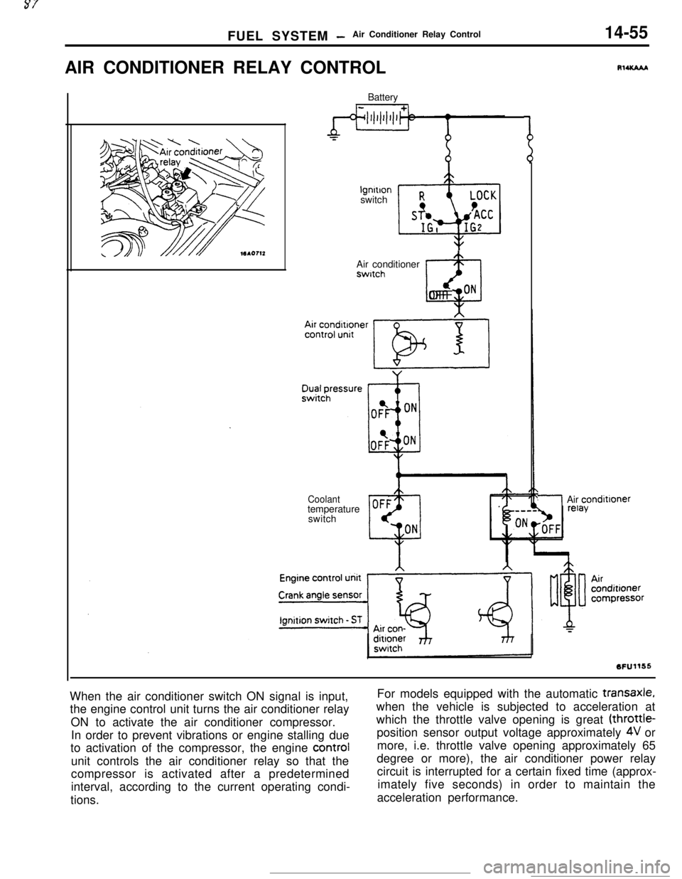
When the air conditioner switch ON signal is input,
the engine control unit turns the air conditioner relay
ON to activate the air conditioner compressor.
In order to prevent vibrations or engine stalling due
to activation of the compressor, the engine control
unit controls the air conditioner relay so that the
compressor is activated after a predetermined
interval, according to the current operating condi-
tions.For models equipped with the automatic
transaxle,when the vehicle is subjected to acceleration at
which the throttle valve opening is great (throttle-
position sensor output voltage approximately
4V or
more, i.e. throttle valve opening approximately 65
degree or more), the air conditioner power relay
circuit is interrupted for a certain fixed time (approx-
imately five seconds) in order to maintain the
acceleration performance.
Page 172 of 391
-.
14-60FUEL SYSTEM - Auto-cruise Control System
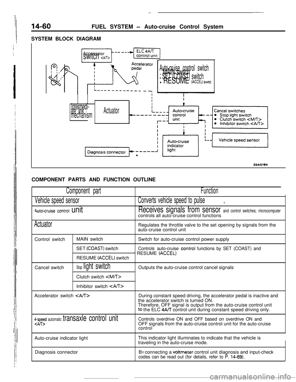
SYSTEM BLOCK DIAGRAM
---
f?,: 0,
,’
vi
switch cpJT>
Auto-cruise control switch. MAIN switchl SET (COAST) switchl RESUME (ACCEL) switc
I
Intermedi-ate linkActuator
mechanismCOMPONENT PARTS AND FUNCTION OUTLINE
Component part
Vehicle speed sensor
6\uto-cruise control unit
Function
Converts vehicle speed to pulse,
Receives signals from sensor and control switches; microcomputercontrols all auto-cruise control functions
ActuatorRegulates the throttle valve to the set opening by signals from the
auto-cruise control unit
Control switchMAIN switch
Switch for auto-cruise control power supply
SET
(COAST) switchControls auto-cruise control functions by SET (COAST) and
1 RESUME (ACCELIRESUME (ACCEL) switch
Cancel switch
Stop light switchClutch switch
Inhibitor switch CA/T>
Accelerator switch
During constant speed driving, the accelerator pedal is inactive and
the accelerator switch is turned ON.
Therefore, OFF signal is output from the auto-cruise control unitto the ELC
4A/T control unit during constant speed driving only.
4-I-Ed automatic transaxle control unitControls overdrive ON and OFF based on overdrive ON andOFF signals from the auto-cruise control unit for the auto-cruise
controlAuto-cruise indicator lightThis indicator light illuminates to indicate that the vehicle is
traveling in the auto-cruise mode.
Diagnosis connectorBY connecting a voltmeter control unit diagnosis and input-check
codes can be read out (for details, refer to P. 14-69).
Page 175 of 391
FUEL SYSTEM - Auto-cruise Control System14-63
FixedDecebFixed
speed -bb-Highration+ c- speed
Vehicle
speedLow
SET ON
switch
OFF
DC StoPmotor Decele-
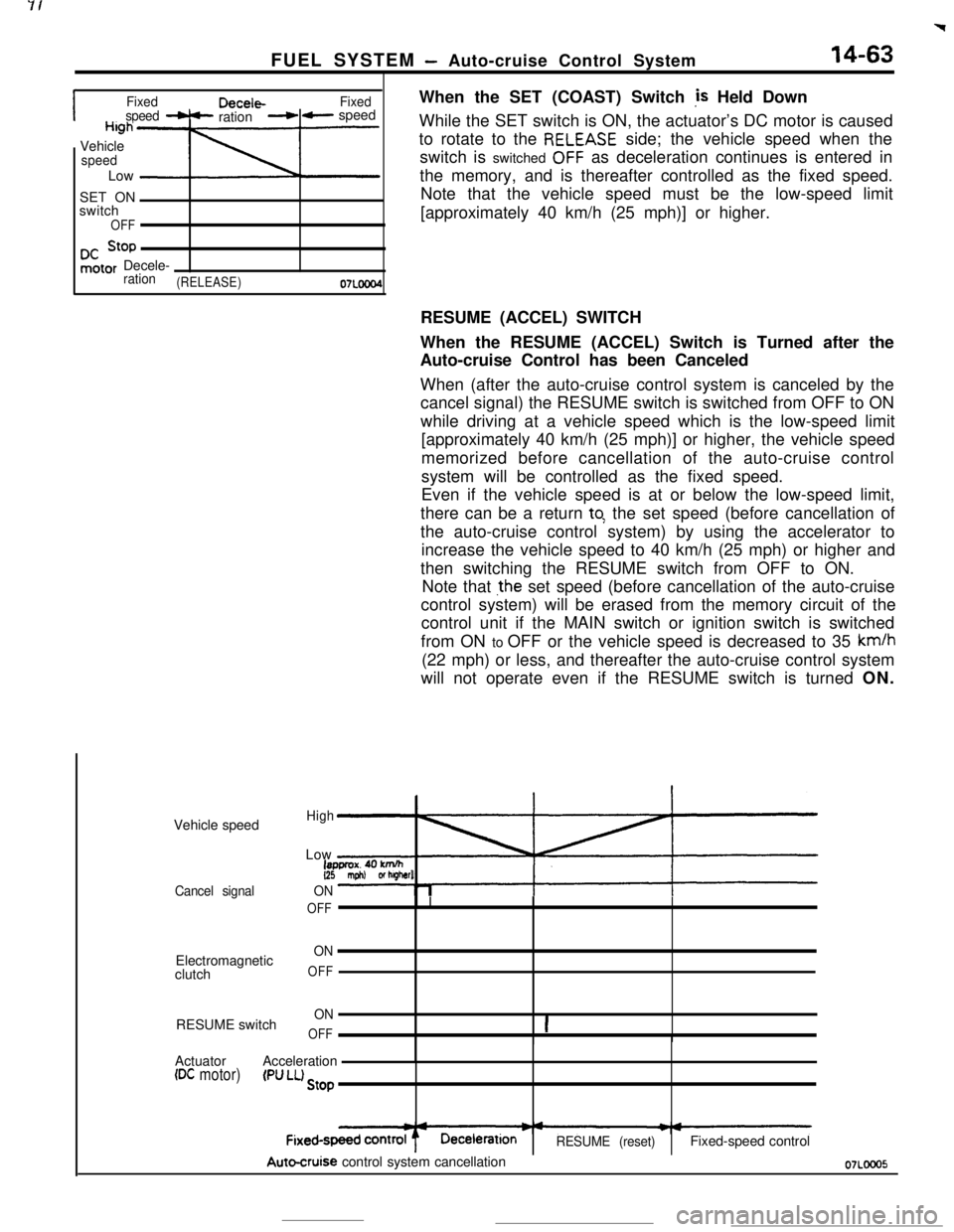
ration(RELEASE)07LOcaWhen the SET (COAST) Switch
,is Held Down
While the SET switch is ON, the actuator’s DC motor is caused
to rotate to the
RELEASE side; the vehicle speed when the
switch is switched
OFF as deceleration continues is entered in
the memory, and is thereafter controlled as the fixed speed.
Note that the vehicle speed must be the low-speed limit
[approximately 40 km/h (25 mph)] or higher.
Vehicle speed
Cancel signalElectromagnetic
clutch
RESUME switchRESUME (ACCEL) SWITCH
When the RESUME (ACCEL) Switch is Turned after the
Auto-cruise Control has been Canceled
When (after the auto-cruise control system is canceled by the
cancel signal) the RESUME switch is switched from OFF to ON
while driving at a vehicle speed which is the low-speed limit
[approximately 40 km/h (25 mph)] or higher, the vehicle speed
memorized before cancellation of the auto-cruise control
system will be controlled as the fixed speed.
Even if the vehicle speed is at or below the low-speed limit,
there can be a return
to: the set speed (before cancellation of
the auto-cruise control system) by using the accelerator to
increase the vehicle speed to 40 km/h (25 mph) or higher and
then switching the RESUME switch from OFF to ON.
Note that
jhe set speed (before cancellation of the auto-cruise
control system) will be erased from the memory circuit of the
control unit if the MAIN switch or ignition switch is switched
from ON to OFF or the vehicle speed is decreased to 35 km/h
(22 mph) or less, and thereafter the auto-cruise control system
will not operate even if the RESUME switch is turned ON.
HighLow
18pprOX.40 knVh(25 mph) or lugharl
ON
OFFI
ON
OFF
ON
OFF1IActuatorAcceleration
(DC motor)(Pff LL) Stop
RESUME (reset)Fixed-speed control
Autocruise control system cancellation07LOOO5
Page 176 of 391
![MITSUBISHI ECLIPSE 1990 User Guide 14-64FUEL SYSTEM - Auto-cruise Control System
FixedAccelera-FixedSpeed -c tion-LC speed
High
Vehic’e iapprox. 40 km/hspeedG!5 mph) or hagher]Low
’When the RESUME
(ACCEL) Switch is Kept Turned
Whi MITSUBISHI ECLIPSE 1990 User Guide 14-64FUEL SYSTEM - Auto-cruise Control System
FixedAccelera-FixedSpeed -c tion-LC speed
High
Vehic’e iapprox. 40 km/hspeedG!5 mph) or hagher]Low
’When the RESUME
(ACCEL) Switch is Kept Turned
Whi](/img/19/57103/w960_57103-175.png)
14-64FUEL SYSTEM - Auto-cruise Control System
FixedAccelera-FixedSpeed -c tion-LC speed
High
Vehic’e iapprox. 40 km/hspeedG!5 mph) or hagher]Low
’When the RESUME
(ACCEL) Switch is Kept Turned
While the RESUME switch is ON, the actuator’s DC
mote,caused to rotate to the PULL side; the vehicle speed when the
switch is switched OFF as acceleration continues is entered in
the memory, and is thereafter controlled as the fixed speed.
CANCELLATION
When, during fixed-speed driving, the signals described below
are input, conductivity to the electromagnetic clutch is inter-
rupted, thus
cancelling the auto-cruise control system.
l Stop light switch ON (brake pedal depressed)
l Clutch switch ON (clutch pedal depressed)
lInhibitor switch ON (selector lever at
“P” or “N” position)
LOW-SPEED LIMIT
There is automatic cancellation at or below the low-speed limit
vehicle speed [approximately 40 km/h (25 mph)].
HIGH-SPEED LIMIT
The vehicle cannot be driven at a fixed speed which is at or
higher than the high-speed limit [approximately 145 km/h
(90
mph)l.Note that the vehicle speed memorized when the SET switch
a5pressed while the vehicle is traveling at the high-speed limit or
higher
vvill be the high-speed limit vehicle speed.
FAIL-SAFE FUNCTION
When the following situations are encountered during fixed-
speed driving, the signals to interrupt, conductivity to the
electromagnetic clutch are input, thus canceling the auto-cruise
control system.
0
0
0When vehicle speed decreases to the low-speed limit
[approx. 40 km/h (25 mph)].
If the vehicle speed decreases to a speed which is
approximately 20 km/h (12 mph) or more below ‘the
memorized vehicle speed.
When the vehicle speed drops by 20 km/h
(12 mph) or more
after having reached the set speed -10 km/h (-6 mph) in
the RESUME mode.
If there is damaged or disconnected wiring of the input line
(stop light switch load side) of the stop light switch.
if there is no input of the vehicle speed signal for a certain
fixed time (1 second or longer).
If the SET and RESUME control switches are switched ON
at the same time.
If the cancel switches (stop light switch, clutch switch or
inhibitor switch) and command switches (SET switch
orRESUME switch) are switched ON at the same time.
if the actuator clutch driver (transistor) of the control unk
remains ON (short-circuit).
Page 177 of 391
