oil filter MITSUBISHI ECLIPSE 1991 Service Manual
[x] Cancel search | Manufacturer: MITSUBISHI, Model Year: 1991, Model line: ECLIPSE, Model: MITSUBISHI ECLIPSE 1991Pages: 1216, PDF Size: 67.42 MB
Page 35 of 1216
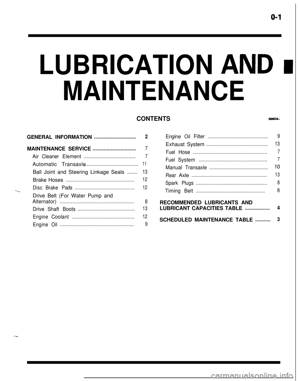
LUBRICATION AND’ I
MAINTENANCE
CONTENTSGENERAL INFORMATION
..............................2MAINTENANCE SERVICE
...............................7Air
CleanerElement.....................................7Automatic Transaxle....................................
11Ball Joint and Steering Linkage Seals
........13Brake Hoses
.................................................12
DiscBrakePads...........................................12-lbDrive Belt (For Water Pump and
Alternator).....................................................8
DriveShaftBoots.........................................13
EngineCoolant.............................................12
EngineOil.....................................................9
EngineOilFilter...........................................9Exhaust System
............................................13
FuelHose.....................................................7
FuelSystem.................................................7
ManualTransaxle..........................................10
RearAxle......................................................13
SparkPlugs...................................................8
TimingBelt......................................................8RECOMMENDED LUBRICANTS AND
LUBRICANT CAPACITIES TABLE
..................4SCHEDULED MAINTENANCE TABLE
............3
Page 37 of 1216
LUBRICATION AND MAINTENANCE - Scheduled MaintenanCe Table. &3
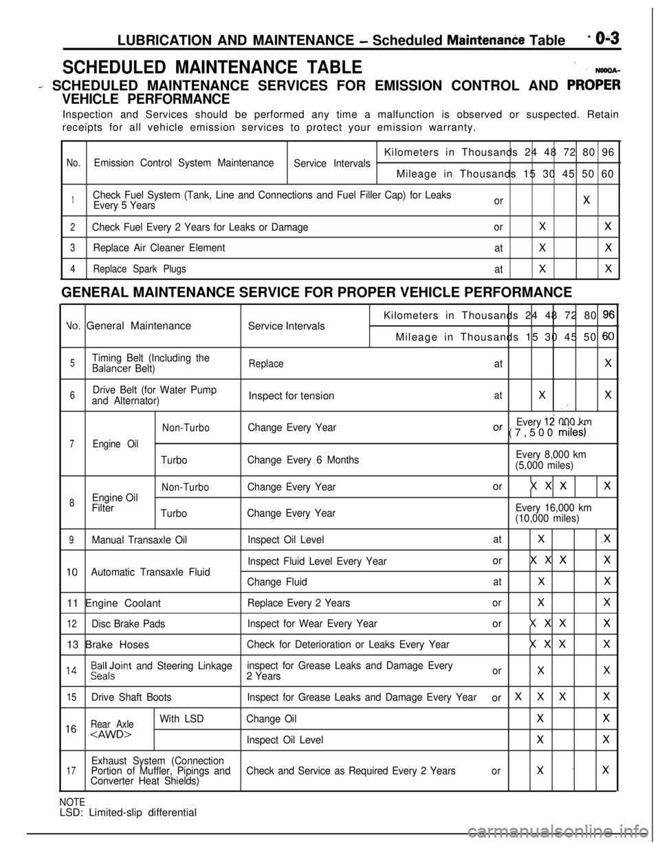
SCHEDULED MAINTENANCE TABLE1
- SCHEDULED MAINTENANCE SERVICES FOR EMISSION CONTROL AND PRO;;
VEHICLE PERFORMANCEInspection and Services should be performed any time a malfunction is observed or suspected. Retain
receipts for all vehicle emission services to protect your emission warranty.
Kilometers in Thousands 24 48 72 80 96
No.Emission Control System Maintenance
Service IntervalsMileage in Thousands 15 30 45 50 60
1Check Fuel System (Tank, Line and Connections and Fuel Filler Cap) for Leaks
Every 5 YearsorX
2Check Fuel Every 2 Years for Leaks or DamageorXX
3Replace Air Cleaner Element
atXX
4Replace Spark Plugs
atXXGENERAL MAINTENANCE SERVICE FOR PROPER VEHICLE PERFORMANCE
Yo. General Maintenance
Service IntervalsKilometers in Thousands 24 48 72 80 9cMileage in Thousands 15 30 45 50
6C
5Timing Belt (Including theBalancer Belt)ReplaceatX
6Drive Belt (for Water Pump
and Alternator)Inspect for tensionatXX.’
Non-TurboChange Every YearEvery 12 000 kmOr (7,500 miles).
7Engine Oil
TurboChange Every 6 MonthsEvery 8,000 km
(5,000 miles)
Non-TurboChange Every Yearor X X XX
8Engine Oil
Filter
TurboChange Every YearEvery 16,000 km
(10,000 miles)
9Manual Transaxle OilInspect Oil LevelatX.X
Inspect Fluid Level Every Yearor X X XX
10Automatic Transaxle Fluid
Change FluidatXX11 Engine Coolant
Replace Every 2 YearsorXX
12Disc Brake PadsInspect for Wear Every Yearor X X XX13 Brake Hoses
Check for Deterioration or Leaks Every YearX X XX
l 4Beiloint and Steering Linkageinspect for Grease Leaks and Damage Every
2 YearsorXX
15Drive Shaft BootsInspect for Grease Leaks and Damage Every Yearor XXXX
Rear Axle
With LSDChange OilXX1 6
Exhaust System (Connection17Portion of Muffler, Pipings andCheck and Service as Required Every 2 Yearsorx -xConverter Heat Shields)
NOTELSD: Limited-slip differential
Page 38 of 1216
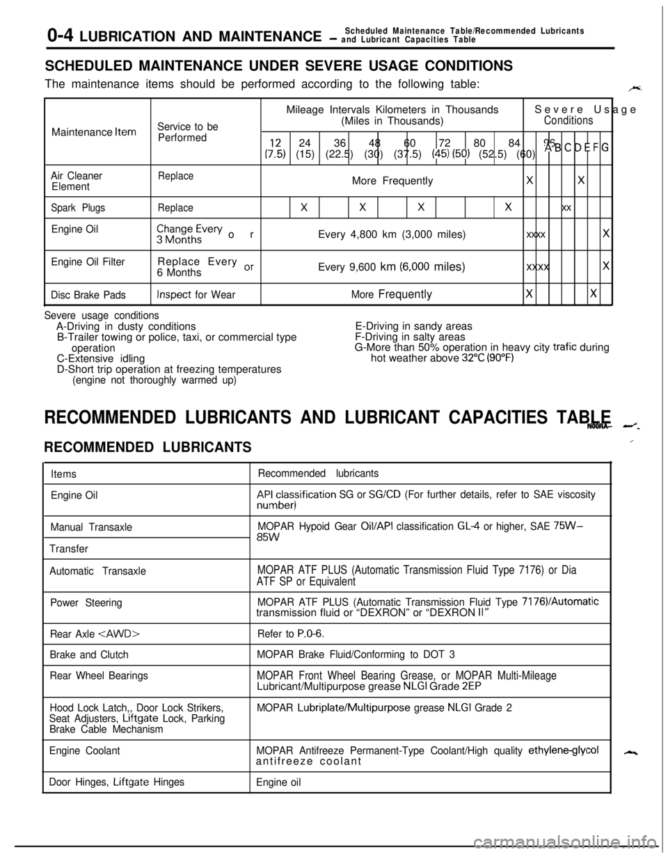
0-4 LUBRICATION AND MAINTENANCEScheduled Maintenance Table/Recommended Lubricants- and Lubricant Capacities TableSCHEDULED MAINTENANCE UNDER SEVERE USAGE CONDITIONS
The maintenance items should be performed according to the following table:
F.Mileage Intervals Kilometers in ThousandsSevere Usage
Service to be(Miles in Thousands)ConditionsMaintenance
Item
Performed24 36 48 60 72 80 84 96
(:,:) (15) (22.5) (30) (37.5) (45) (50) (52.5) (60) * B ’ D E F G
Air CleanerReplaceElementMore FrequentlyXX
Spark PlugsReplace
XXXx xx
Engine Oil$$~~~h~vev orEvery 4,800 km (3,000 miles)xxxx x
Engine Oil FilterReplace Every or6 MonthsEvery 9,600 km (6,000 miles)xxxx x
Disc Brake PadsInspect for WearMore FrequentlyXX
Severe usage conditionsA-Driving in dusty conditionsE-Driving in sandy areas
B-Trailer towing or police, taxi, or commercial typeF-Driving in salty areas
operationG-More than 50% operation in heavy city trafic during
C-Extensive idlinghot weather above 32°C (90°F)D-Short trip operation at freezing temperatures
(engine not thoroughly warmed up)
RECOMMENDED LUBRICANTS AND LUBRICANT CAPACITIES TABLENOONA- --z.
RECOMMENDED LUBRICANTS
Items
Engine Oil
Manual Transaxle
TransferRecommended lubricantskF&cesisification
SG or SG/CD (For further details, refer to SAE viscosity
MOPAR Hypoid Gear
Oil/API classification GL4 or higher, SAE 75W-85W
Automatic TransaxleMOPAR ATF PLUS (Automatic Transmission Fluid Type 7176) or Dia
ATF SP or Equivalent
Power SteeringMOPAR ATF PLUS (Automatic Transmission Fluid Type 7176VAutomatictransmission fluid or “DEXRON” or “DEXRON II”
Rear Axle
Brake and Clutch
Rear Wheel BearingsRefer to
P.O-6.
MOPAR Brake Fluid/Conforming to DOT 3
MOPAR Front Wheel Bearing Grease, or MOPAR Multi-MileageLubricant/Multipurpose grease NLGI Grade 2EP
Hood Lock Latch,, Door Lock Strikers,
Seat Adjusters, Lrftgate Lock, Parking
Brake Cable MechanismMOPAR Lubriplate/Multipurpose grease NLGI Grade 2
Engine CoolantMOPAR Antifreeze Permanent-Type Coolant/High quality
ethylene-glycolantifreeze coolant
Door Hinges, Liftgate Hinges
Engine oil
/
N
Page 39 of 1216
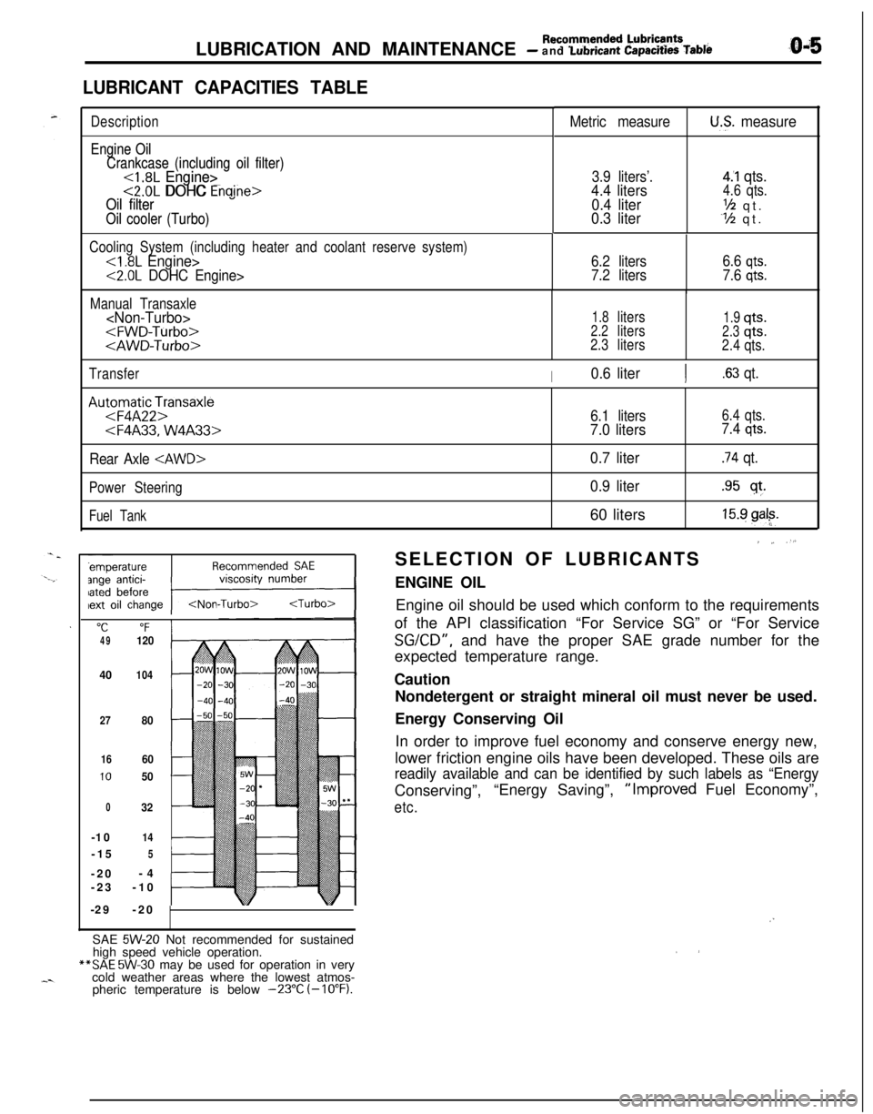
LUBRICATION AND MAINTENANCE - Recommended Lubrie’ntsand Lubrtcant Capacttles Table
LUBRICANT CAPACITIES TABLE
Description
Engine Oil Engine Oil
Crankcase (including oil filter) Crankcase (including oil filter)
<1.8L Engine><1.8L Engine><2.0L DOHC Engine><2.0L DOHC Enaine>Oil filter Oil filter
Oil cooler (Turbo) Oil cooler (Turbo)
Metric measureU.S. measure
3.9 liters’.4.4 liters
0.4 liter
0.3 liter
4.‘1 qts.4.6 qts.
‘h qt.Y2 qt.
Cooling System (including heater and coolant reserve system)
<2.0L DOHC Engine>6.2 liters
7.2 liters6.6
qts.
7.6 qts.
Manual Transaxle
1.8liters1.9qts.2.2liters2.3qts.
2.3liters
2.4qts.
Transfer
I0.6 literI.63 qt.
Au:oFmqaAtF2pnsaxle
Rear Axle
Power Steering
Fuel Tank
"C“F4912040
104
27
80
1660
1050
032-10
14-15
5-20-4
-23-10
-29-20
6.1 liters6.4 qts.
7.0 liters7.4 qts.
0.7 liter.74 qt.
0.9 liter.95 sf.60 liters
15.9 gal?.
’ ~ “.SELECTION OF LUBRICANTS
ENGINE OIL
Engine oil should be used which conform to the requirements
of the API classification “For Service SG” or “For Service
SGKD”, and have the proper SAE grade number for the
expected temperature range.
Caution
Nondetergent or straight mineral oil must never be used.
Energy Conserving Oil
In order to improve fuel economy and conserve energy new,
lower friction engine oils have been developed. These oils are
readily available and can be identified by such labels as “EnergyConserving”,“Energy Saving”,“Improved Fuel Economy”,
etc.
/”SAE
5W-20 Not recommended for sustained
high speed vehicle operation.**SAE
5W-30 may be used for operation in very
cold weather areas where the lowest atmos-
pheric temperature is below
-23°C (-10°F).
Page 43 of 1216
LUBRICATION AND MAINTENANCE - Maintenance ServiceO-9
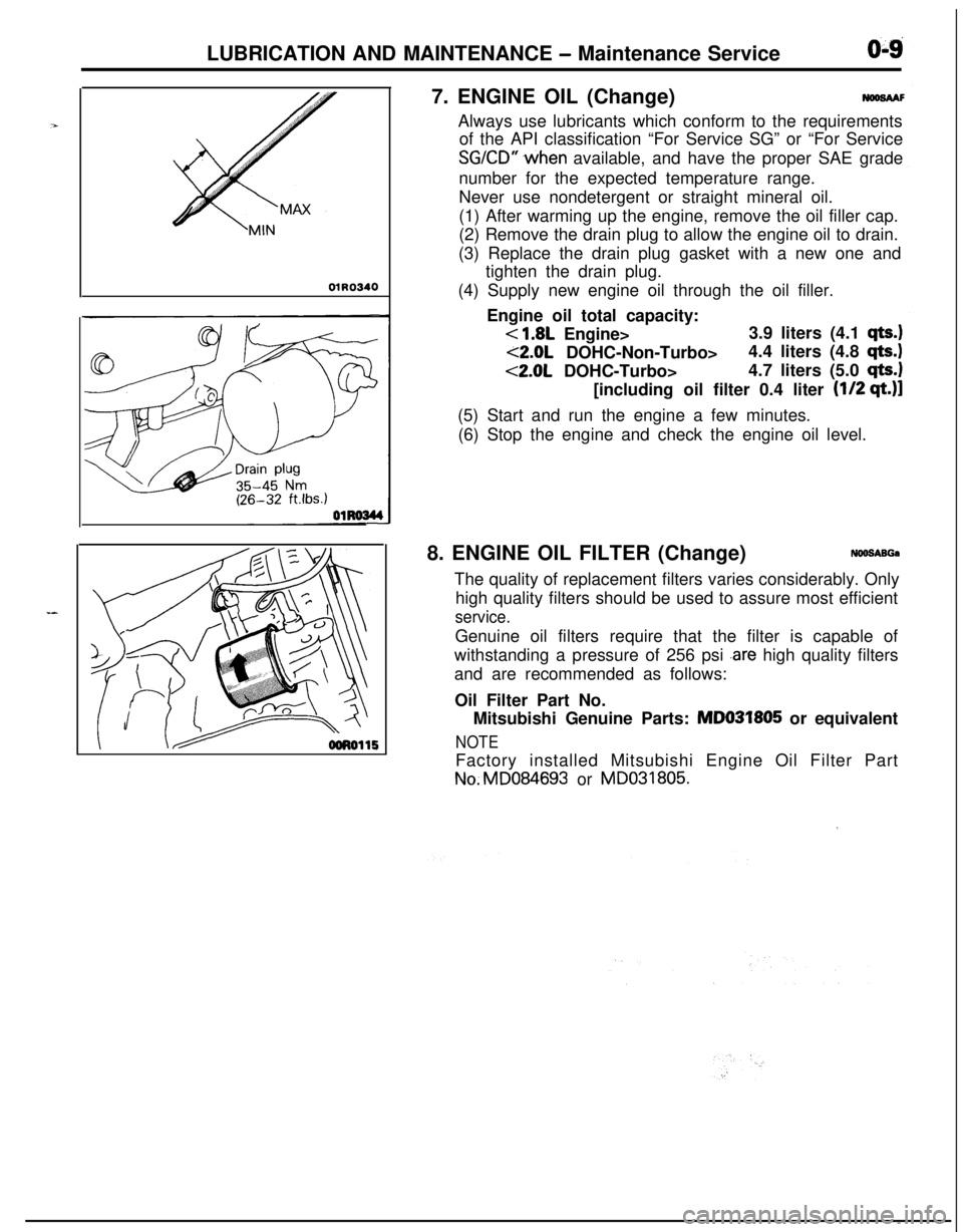
01R03407. ENGINE OIL (Change)
NWSAAFAlways use lubricants which conform to the requirements
of the API classification “For Service SG” or “For Service
SGKD” .when available, and have the proper SAE grade
number for the expected temperature range.
Never use nondetergent or straight mineral oil.
(1) After warming up the engine, remove the oil filler cap.
(2) Remove the drain plug to allow the engine oil to drain.
(3) Replace the drain plug gasket with a new one and
tighten the drain plug.
(4) Supply new engine oil through the oil filler.
Engine oil total capacity:
< 1.8L Engine>3.9 liters (4.1 qts.)
<2.0L DOHC-Non-Turbo>4.4 liters (4.8 qts.)
<2.0L DOHC-Turbo>4.7 liters (5.0 qts.1[including oil filter 0.4 liter
(l/2 qt.)]
(5) Start and run the engine a few minutes.
(6) Stop the engine and check the engine oil level.
8. ENGINE OIL FILTER (Change)
NOO!SABGaThe quality of replacement filters varies considerably. Only
high quality filters should be used to assure most efficient
service.Genuine oil filters require that the filter is capable of
withstanding a pressure of 256 psi
.are high quality filters
and are recommended as follows:
Oil Filter Part No.
Mitsubishi Genuine Parts: MD031805 or equivalent
NOTEFactory installed Mitsubishi Engine Oil Filter PartNo.MD084693 or MD031805.
’
Page 44 of 1216
LUBRICATION AND MAINTENANCE - Maintenance Service
osFol2ENGINE
OIL FtLTER SELECTtONThis vehicle is equipped with a full-flow, throw-away oil
,~
filter.The same type of replacement filter is recommended as a
replacement filter for this vehicle. It is possible, particularilyin cold weather, that this vehicle may develop high oil
pressure for a short duration. You should be sure that any
replacement filter used on this vehicle is a high-quality filterand is capable of withstanding a pressure of 256 psi
(manufacturer’s specifications) to avoid filter and engine
damage. The following is a high-quality filter and is stronglyrecommended for use on this vehicle
: Mitsubishi Engine
-Oil Filter Part No. MD031805 or MD084693.
Any replacement oil filter should be installed in accordancewith the oil filter manufacturer’s installation instructions.
(1) Remove the engine oil filler cap.
(2) Remove the engine oil drain plug, and drain out the
engine oil.
(3) Remove the engine oil filter by using the oil filter
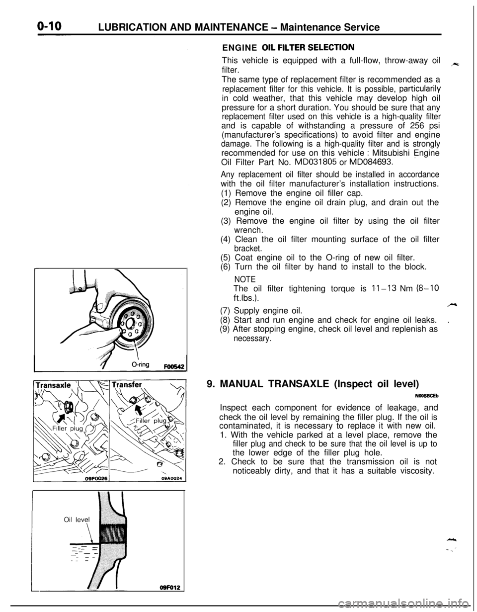
wrench.(4) Clean the oil filter mounting surface of the oil filter
bracket.(5) Coat engine oil to the O-ring of new oil filter.
(6) Turn the oil filter by hand to install to the block.
NOTEThe oil filter tightening torque is
11-13 Nm (8-10
ftlbs.).A(7) Supply engine oil.
.(8) Start and run engine and check for engine oil leaks.
(9) After stopping engine, check oil level and replenish as
necessary.9. MANUAL TRANSAXLE (Inspect oil level)
NOOSBCEbInspect each component for evidence of leakage, and
check the oil level by remaining the filler plug. If the oil is
contaminated, it is necessary to replace it with new oil.
1. With the vehicle parked at a level place, remove the
filler plug and check to be sure that the oil level is up tothe lower edge of the filler plug hole.
2. Check to be sure that the transmission oil is not
noticeably dirty, and that it has a suitable viscosity.
Page 45 of 1216
LUBRICATION AND MAINTENANCE - Maintenance ServiceO:lllO.AUTOMATIC TRANSAXLE (Inspect fluid
I~~+v~!1. Drive until the fluid temperature reaches the usual
temperature
[70-80°C (160- 18O”F)l.2. Place vehicle on level floor.
3.Move selector lever sequentially to every position to fill
torque converter and hydraulic
circuitwith fluid, then
place lever in“N” Neutral position. This operation is
necessary to be sure that fluid level check is accurate.
4.Before removing dipstick, wipe all dirt from area arounddipstick. Then take out the dipstick and check the
condition of the fluid.
The transaxle should be overhauled under the following
conditions.l If there is a “burning” odor.
l If the fluid color has become noticeably blacker.
l If there is a noticeably great amount of metal
particles in the fluid.
5.Check to see if fluid level is in “HOT” range on dipstick.If fluid level is low, add ATF until level reaches “HOT”
range.Low fluid level can cause a variety of conditions
because it allows pump to take in air along with fluid. Airtrapped in hydraulic circuit forms bubbles which make
fluid spongy. Therefore, pressures will be erratic.
Improper filling can also raise fluid level too high. Whentransaxle has too much fluid, gears churn up foam and
cause same conditions which occur with low fluid level,resulting in accelerated deterioration of ATF.
transmission fluid.
In either case, air bubbles can cause overheating, fluid
oxidation, which can interfere with normal valve, clutch,and servo operation. Foaming can also result in fluid
escaping from transaxle vent where it may be mistakenfor a leak.
6. Be sure to examine fluid on dipstick closely.lO.AUTOMATIC TRANSAXLE (Change fluid)
Drain the fluid and check whether there is any evidence of
contamination.
Replenish with new fluid after the cause of any contamina-tion has been corrected.
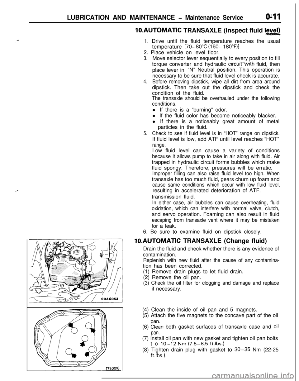
(1) Remove drain plugs to let fluid drain.
(2) Remove the oil pan.
(3) Check the oil filter for clogging and damage and replaceif necessary.
(4) Clean the inside of oil pan and 5 magnets.
(5) Attach the five magnets to the concave part of the oil
(6)
Elan both gasket surfaces of transaxle case and oil
pan.(7) Install oil pan with new gasket and tighten oil pan bolts
to
IO-12 Nm (7.5-8.5 ft.lbs.1(8) Tighten drain plug with gasket to
30-35 Nm (22-25
ftlbs.).
Page 185 of 1216
BRAKES - Service Adiustment Procedures5-45I
\\14A0416
2314A04.54
BLEEDINGN65FYAN
When the master cylinder is empty of brake fluid, bleed air
from the master cylinder by proceeding with procedures (1)
thru (6). (Because this master cylinder is not equipped with a
check valve.)
When brake fluid remains in the master cylinder, proceed with
step (6).
(1) -Disconnect the brake tube from the master cylinder.
(2) Two persons should conduct the air bleeding, one person
slowly depressing the brake pedal and holding the pedal
depressed.(3) In this condition, the other person should use a finger to
close the outlet part of the master cylinder, and then the
first person should release the brake pedal.
(4) Steps (2) and (3) should be repeated three or four times,
and then the master cylinder should be filled with brake
fluid to the specified level.
NOTE
The air is completely bled from the master cylinder by steps
(1) to (4).
(5) Connect the brake tube to the master cylinder.
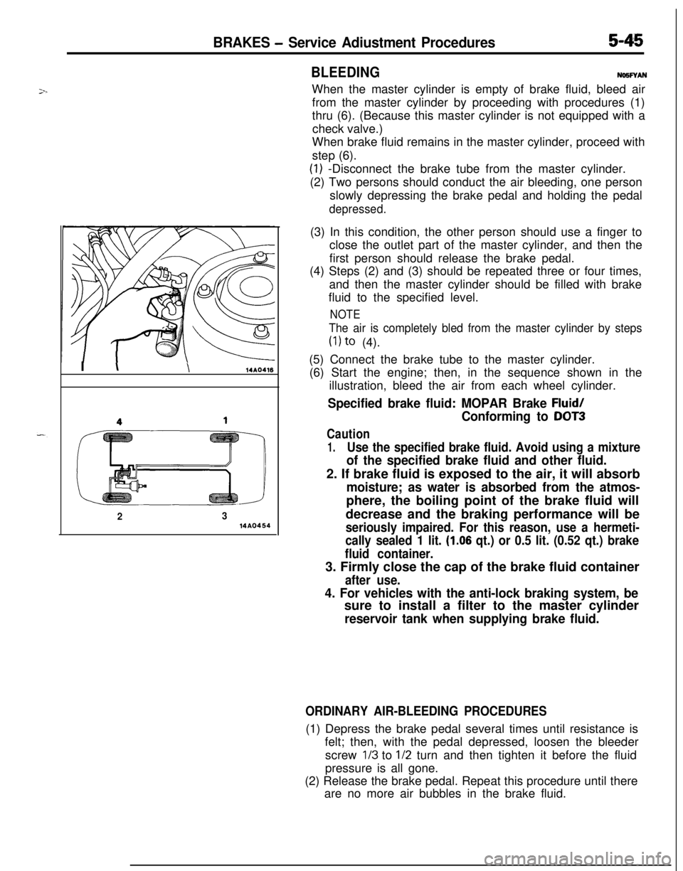
(6) Start the engine; then, in the sequence shown in the
illustration, bleed the air from each wheel cylinder.
Specified brake fluid: MOPAR Brake Fluid/
Conforming to DOT3
Caution
1.Use the specified brake fluid. Avoid using a mixture
of the specified brake fluid and other fluid.2. If brake fluid is exposed to the air, it will absorb
moisture; as water is absorbed from the atmos-phere, the boiling point of the brake fluid will
decrease and the braking performance will be
seriously impaired. For this reason, use a hermeti-
cally sealed 1 lit.
(1.06 qt.) or 0.5 lit. (0.52 qt.) brake
fluid container.3. Firmly close the cap of the brake fluid container
after use.
4. For vehicles with the anti-lock braking system, besure to install a filter to the master cylinder
reservoir tank when supplying brake fluid.
ORDINARY AIR-BLEEDING PROCEDURES(1) Depress the brake pedal several times until resistance is
felt; then, with the pedal depressed, loosen the bleeder
screw
l/3 to l/2 turn and then tighten it before the fluid
pressure is all gone.
(2) Release the brake pedal. Repeat this procedure until there
are no more air bubbles in the brake fluid.
Page 291 of 1216
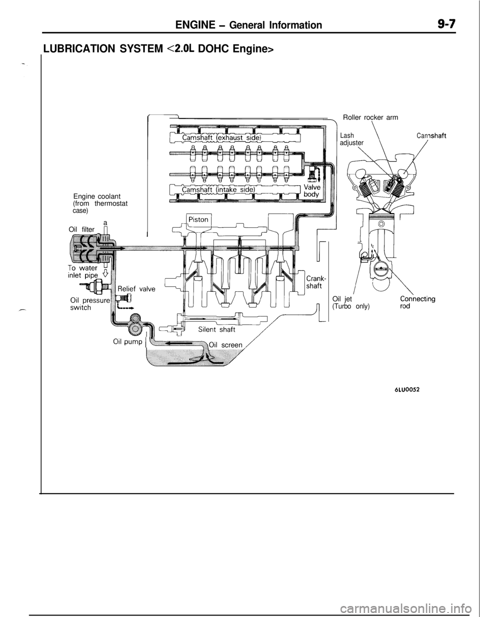
ENGINE - General Information9-7
LUBRICATION SYSTEM <2.0L DOHC Engine>Engine coolant
(from thermostat
case)a
Oil filterRoller rocker arm
LashadjusterCan
/
ILt
K
63
ishaftOil jet
(Turbo only)
Oil pump I y+Oilscreen /6LUOO52
Page 302 of 1216
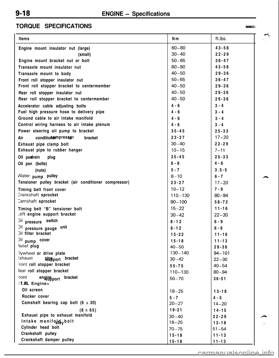
9-18ENGINE - Specifications
TORQUE SPECIFICATIONS
NO9CG-Items
Engine mount insulator nut (large)
(small)
Engine mount bracket nut or bolt
Transaxle mount insulator nut
Transaxle mount to body
Front roll stopper insulator nut
Front roll stopper bracket to centermember
Rear roll stopper insulator nut
Rear roll stopper bracket to centermember
Accelerator cable adjusting bolts
Fuel high pressure hose to delivery pipe
Ground cable to air intake manifold
Control wiring harness to air intake plenum
Power steering oil pump to bracket
Air conditioner to bracketcompressor
Exhaust pipe clamp bolt
Exhaust pipe to rubber hanger
Oil drain plug
panOil (bolts)
pan(nuts)VVater pulley
pump
Tensioner pulley bracket (air conditioner compressor)
Timing belt front coverCrankshaft sprocket
Camshaft sprocket
Timing belt “B” tensioner bolt
-eft engine support bracket3il switch
pressure3il unit
pressure gauge
Iii filter bracket
Iii cover
pumpqelief plug
‘lywheel or drive plate
ixhaust pipe bracket
support
‘rant roll stopper bracket
Iear roll stopper bracket‘rant engine bracket
support
:1.8L Engine>
Oil screen
Rocker cover
Camshaft bearing cap bolt (6 x 20)
(8 x 65)
Exhaust pipe to exhaust manifold
Intake manifold bolt
stay
Cylinder head bolt
Crankshaft pulley
Crankshaft damper pulleyNm
ftlbs.
60-8043-58
30-4022-29
50-6536-47
60-8043-58
40-5029-36
50-6536-47
40-5029-36
40-5029-36
40-5029-36
4-63-4
4-6
3-4
4-6
3-4
4-6
3-4
35-45
25-33
23-27
17-20
30-4022-29
10-157-l 135-45
25-33
6-84-6
5-73.5-5
8-106-7
23-27
17-20
10-127-9
110-13080-94
80-10058-72
15-2211-16
30-4222-308-126-9
8-126-9
15-2211-16
15-1811-13
40-5029-36
130-14094-101
30-4222-3055-75
40-54
110-13080-94
50-7036-51
18-2513-18
5-74-5
20-2714-2019-21
14-15
30-4022-29
18-2513-18
70-7551-5415-1811-13
15-1811-13