oil filter MITSUBISHI ECLIPSE 1991 User Guide
[x] Cancel search | Manufacturer: MITSUBISHI, Model Year: 1991, Model line: ECLIPSE, Model: MITSUBISHI ECLIPSE 1991Pages: 1216, PDF Size: 67.42 MB
Page 303 of 1216
-
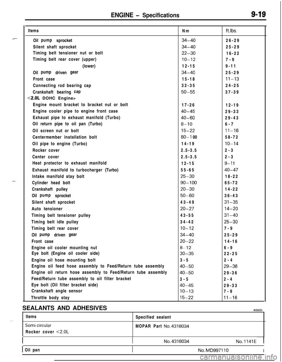
ENGINE - Specifications9-19Items
Oil sprocketpump
Silent shaft sprocket
Timing belt tensioner nut or bolt
Timing belt rear cover (upper)
(lower)
Oil drivenpump gear
Front case
Connecting rod bearing cap
Crankshaft bearingcap
<2.0L DOHC Engine>
Engine mount bracket to bracket nut or bolt
Engine cooler pipe to engine front case
Exhaust pipe to exhaust manifold (Turbo)
Oil return pipe to oil pan (Turbo)
Oil screen nut or bolt
Centermember installation bolt
Oil pipe to engine (Turbo)
Rocker cover
Center cover
Heat protector to exhaust manifold
Exhaust manifold to turbocharger(Turbo)
Intake manifold stay bolt
Cylinder head bolt
Crankshaft pulley
Oil sprocketpump
Silent shaft sprocket
Auto tensioner
Timing belt tensioner pulley
Timing belt idle pulley
Timing belt rear cover
Oil drivenpump gear
Front case
Engine oil cooler mounting nut
Eye bolt (Engine oil cooler side)
Engine oil hose mounting bolt
Engine oil feed hose assembly to Feed/Return tube assembly
Engine oil return hose assembly to Feed/Return tube assembly
Feed/Return tube assembly to oil filter bracket
Eye bolt (Oil filter bracket side)
Crankshaft angle sensor
Throttle body stayNm
ft.lbs.
34-4026-29
34-4025-29
22-3016-22
IO-127-9
12-159-11
34-4025-29
15-18
11-1332-3524-25
50-5537-39
17-26
12-19
40-4529-33
40-6029-43
8-106-7
15-2211-16
80-l 0058-72
14-19
10-142.5-3.52-3
2.5-3.52-3
12-15
9-l 155-65
40-47
25-3018-22
90-10065-72
20-3014-22
50-6036-43
43-49
31-35
20-2714-2043-55
31-4034-42
25-30
10-127-9
34-4025-29
20-2214-16
8-126-9
30-3522-25
3-52-4
40-5029-36
40-5029-36
3-52-4
40-4529-33
IO-137-9
15-2211-16SEALANTS AND ADHESIVES
NOSCE-.Items
Specified sealant
“. _
SemiWrcularMOPAR Part No.4318034Rocker cover
<2.0L
1(No.4318034No.1141~1
1 Oil pan1No.MD997110I
Page 307 of 1216
ENGINE - Troubleshooting9-23
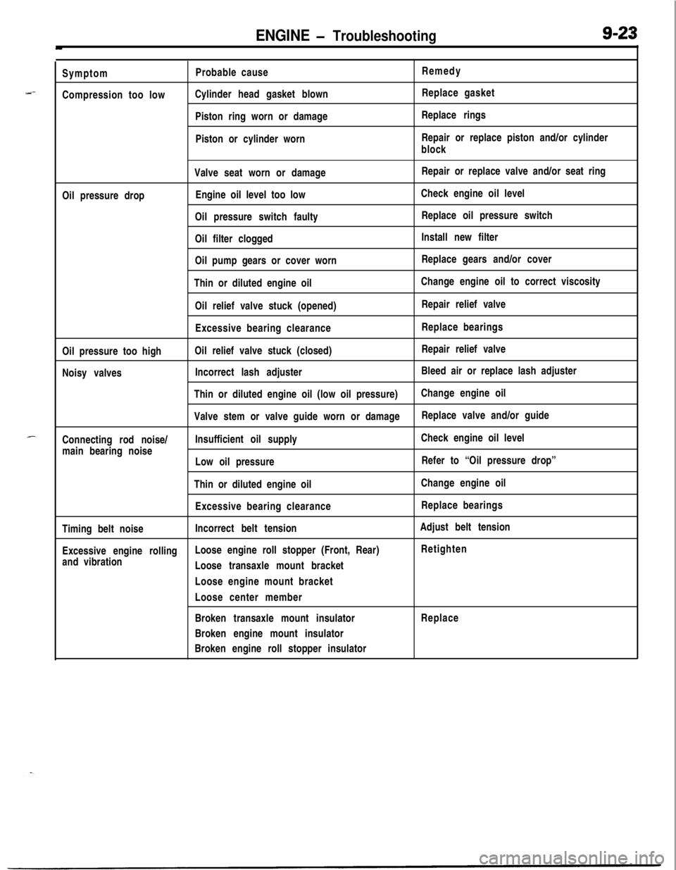
--Symptom
Compression too lowProbable cause
Cylinder head gasket blown
Piston ring worn or damage
Piston or cylinder wornRemedy
Replace gasket
Replace rings
Repair or replace piston and/or cylinder
block
Valve seat worn or damageRepair or replace valve and/or seat ring
Oil pressure dropEngine oil level too lowCheck engine oil level
Oil pressure switch faultyReplace oil pressure switch
Oil filter cloggedInstall new filter
Oil pump gears or cover wornReplace gears and/or cover
Thin or diluted engine oilChange engine oil to correct viscosity
Oil relief valve stuck (opened)Repair relief valve
Excessive bearing clearanceReplace bearings
Oil pressure too highOil relief valve stuck (closed)Repair relief valve
Noisy valvesIncorrect lash adjusterBleed air or replace lash adjuster
Thin or diluted engine oil (low oil pressure)Change engine oil
Valve stem or valve guide worn or damageReplace valve and/or guide
Connecting rod noise/Insufficient oil supplyCheck engine oil level
main bearing noise
Low oil pressureRefer to “Oil pressure drop”
Thin or diluted engine oilChange engine oil
Excessive bearing clearanceReplace bearings
Timing belt noiseIncorrect belt tensionAdjust belt tension
Excessive engine rollingLoose engine roll stopper (Front, Rear)Retighten
and vibration
Loose transaxle mount bracket
Loose engine mount bracket
Loose center member
Broken transaxle mount insulatorReplace
Broken engine mount insulator
Broken engine roll stopper insulator
Page 342 of 1216
9-58ENGINE <1.8L Engine> -Front Case, Oil Pump and Silent Shaft
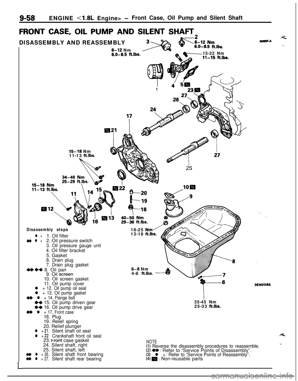
FRONT CASE, OIL PUMP AND SILENT SHAFTrl
L
I1
26:
25
15-18 Nm
11-13 ftlbs.DISASSEMBLY AND REASSEMBLY8-12 Nm
6.0-8.5 ft.lbs.15-22 Nm11-15 ft.lbs.
Disassembly steps
l +1. Oil filter~~ l +2. Oil pressure switch
3. Oil pressure gauge unit4. Oil filter bracket
5. Gasket
6. Drain plug
7. Drain plug gasket
+e*+ 8. Oil pan
9. Oil screen10. Oil screen gasket
11. Oil pump cover18-25
Nm/13-18 ftlbs.
8-8 Nm
4-8 ft.lbs.
l + 12. Oil pump oil seall + 13. Oil pump gasket
~~ l + 14. Flange boltI)+ 15. Oil pump driven geare+ 16. Oil pump drive gear
+e l + 17. Front case18. Plug
19. Relief spring20. Relief plunger
l + 21.Silent shaft oil seal
l + 22.Crankshaft front oil seal
35-45 Nm25-33 ftlbs.23.
Front case gasket
24. Silent shaft, right
25. Silent shaft, left
4* l + 26.Silent shaft front bearing~~ l + 27.Silent shaft rear bearing
i=G.NogRF-A.r
3EN0088
NOTE(1) Reverse the disassembly procedures to reassemble.(2) +e : Refer to “Service Points of Disassembly”.(3) l + : Refer to “Service Points of Reassembly”.(4) 0 : Non-reusable parts
Page 348 of 1216
9-64ENGINE 4.8L Engine> -Front Case, Oil Pump and Silent Shaft
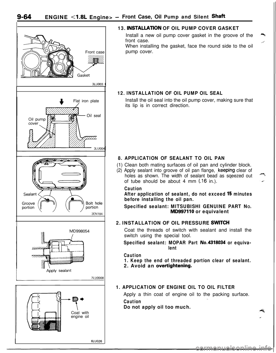
13.
INSTALLATlON OF OIL PUMP COVER GASKETInstall a new oil pump cover gasket in the groove of the
front case.
Front caseWhen installing the gasket, face the round side to the oil
pump cover.
3LUOO3 I
Flat iron plate
3EN184
MD998054
/
-----me
tCoat with
engine oil
6LUO26
12. INSTALLATION OF OIL PUMP OIL SEALInstall the oil seal into the oil pump cover, making sure that
its lip is in correct direction.
8. APPLICATION OF SEALANT TO OIL PAN(1) Clean both mating surfaces of oil pan and cylinder block.
(2) Apply sealant into groove of oil pan flange, ~keeping clear of
holes as shown. The width of sealant bead as sqeezed outof tube should be about 4 mm
(.I6 in.).
Caution
After application of sealant, do not exceed l’5 minutes
before installing the oil pan.
Specified sealant: MITSUBISHI GENUINE PART N
O.
MD997110 or equivalent
2. INSTALLATION OF OIL PRESSURE
SWlTCHCoat the threads of switch with sealant and install the
switch using the special tool.
Specified sealant: MOPAR Part No.4318034 or equiva-
lent
Caution
1. Keep the end of threaded portion clear of sealant.2. Avoid an
overtightening.
1. APPLICATION OF ENGINE OIL TO OIL FILTERApply a thin coat of engine oil to the packing surface.
,.Caution
Do not apply oil too much.
Page 401 of 1216
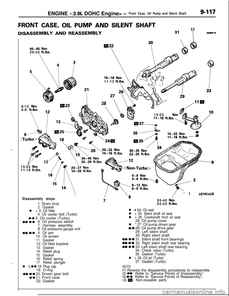
ENGINE <2.0L DOHC Engine> -Front Case, Oil Pump and Silent Shaft9-117
FRONT CASE, OIL PUMP AND SILENT SHAFT
DISASSEMBLY AND REASSEMBLY
40-45 Nm29-33 ft.lbs.
\
32
I
NOSRF-B11-13
ft.lbs.
LO8-12 Nm6-9 ft.lbs.\
\715-22 Nm -11-16 ft.lbs.,15-22
Nm11-16 ft.lbs.
Disassembly steps
I. Drain pluo
\/‘16EN046835-45
Nm25-33 ft.lbs.2.Gasket-l + 3. Oil filter
4. Oil cooler bolt (Turbo)
~~ 5. Oil cooler (Turbo)
6. Oil pressure switch
7.Harness assembly8. Oil pressure gauge unit
9.Oil pan10.Oil screen
11.Gasket12. Oil filter bracket
13.Gasket14.Relief plug
15.Gasket16.Relief spring17.Relief plunger
l 4 23. Oil seall + 24. Silent shaft oil seall + 25. Crankshaft front oil seal26. Oil pump cover
l * 27. Oil pump driven geare+ 28. Oil pump drive gear
29. Left silent shaft
30. Right silent shaft
W W 31. Silent shaft front bearings
W W 32. Right silent shaft rear bearing
~~ ~~ 33. Left silent shaft rear bearing34. Check valve (Turbo)
35. Gasket (Turbo)
l + 36. Oil jet (Turbo)37. Gasket (Turbo)
l I) W 18. Plug cap-NOTE19. O-ring(1) Reverse the disassembly procedures to reassemble.+e I)+ 20. Driven gear bolt(2) 4I) : Refer to “Service Points of Disassembly”.
I)+ 21. Front case(3) ~~ : Refer to “Service Points of Reassembly”.
22. Gasket(4) m : Non-reusable parts
Page 409 of 1216
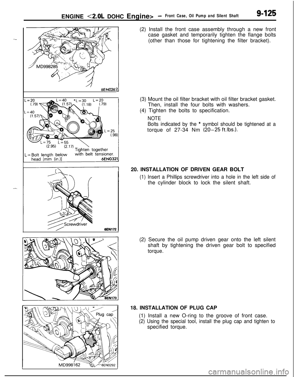
ENGINE <2.0L DOHC Engine> -Front Case, Oil Pump and Silent Shaft9-1256E
N026:(2) Install the front case assembly through a new front
case gasket and temporarily tighten the flange bolts
(other than those for tightening the filter bracket).
(3) Mount the oil filter bracket with oil filter bracket gasket.
Then, install the four bolts with washers.
(4) Tighten the bolts to specification.
NOTE
Bolts indicated by the * symbol should be tightened at atorque of 27-34 Nm
(20-25 ft.1b.s.).20. INSTALLATION OF DRIVEN GEAR BOLT
(1) Insert a Phillips screwdriver into a hole in the left side ofthe cylinder block to lock the silent shaft.
(2) Secure the oil pump driven gear onto the left silent
shaft by tightening the driven gear bolt to specified
torque.18. INSTALLATION OF PLUG CAP
(1) Install a new O-ring to the groove of front case.
(2) Using the special tool, install the plug cap and tighten tospecified torque.
Page 410 of 1216
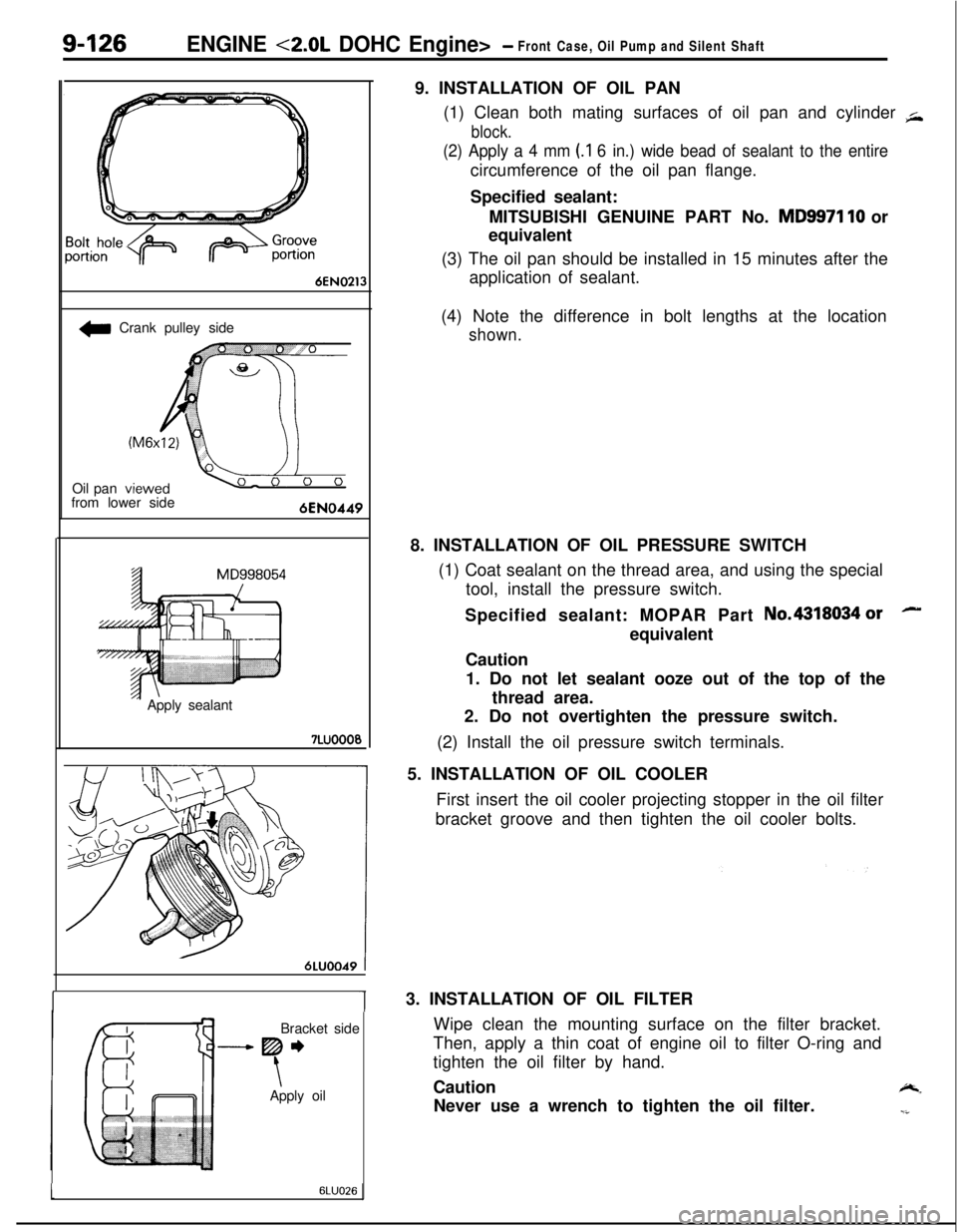
9-126ENGINE <2.0L DOHC Engine>- Front Case, Oil Pump and Silent Shaft
6EN0213
w Crank pulley side
Oil pan
from lower side
‘- Apply sealant7LUOOO0
6LUOO49 tBracket side
-----Be
\Apply oil9. INSTALLATION OF OIL PAN
(1) Clean both mating surfaces of oil pan and cylinder
+
block.
(2) Apply a 4 mm (.I 6 in.) wide bead of sealant to the entirecircumference of the oil pan flange.
Specified sealant:
MITSUBISHI GENUINE PART No.
MD9971 10 or
equivalent
(3) The oil pan should be installed in 15 minutes after the
application of sealant.
(4) Note the difference in bolt lengths at the location
shown.8. INSTALLATION OF OIL PRESSURE SWITCH
(1) Coat sealant on the thread area, and using the special
tool, install the pressure switch.
Specified sealant: MOPAR Part No.4318034
orequivalent
Caution
1. Do not let sealant ooze out of the top of the
thread area.
2. Do not overtighten the pressure switch.
(2) Install the oil pressure switch terminals.
5. INSTALLATION OF OIL COOLER
First insert the oil cooler projecting stopper in the oil filter
bracket groove and then tighten the oil cooler bolts.lu3. INSTALLATION OF OIL FILTER
Wipe clean the mounting surface on the filter bracket.
Then, apply a thin coat of engine oil to filter O-ring and
tighten the oil filter by hand.
Caution
-.Never use a wrench to tighten the oil filter.
-i
16LUO26
Page 455 of 1216
14-IFUEL SYSTEM
CONTENTS
AUTO-CRUISECONTROLSYSTEM...........................................109AUTO-CRUISECONTROL.......................................................140SERVICEADJUSTMENTPROCEDURES..............................135Accelerator Cable, Throttle Cable and Auto-cruise
ControlCableInspectionandAdjustment........................136Auto-cruise
ControlSystemInspection.............................135lndrvrdualPartsInspection..................................................137SPECIFICATIONS.....................................................................109GeneralSpecifications.......................................................109ServiceSpecifications
.........................................................109Torque Specrfications..........................................................109TROUBLESHOOTING...............................................................110Auto-CruiseControlCircurt................................................128Auto-cruise
ControlComponentsLocation........................126Auto-cruise Control Related Harnesses
.............................125Check Chart
........................................................................114Input Check.........................................................................123Self-diagnosis
Check..........................................................121Troubleshootrng
Quick-referenceChart..............................110ENGINECONTROL.......................................................................105ENGINECONTROL..................................................................107--SERVICEADJUSTMENTPROCEDURES..............................106Accelerator Cable Inspection and Adjustment..................106Accelerator Switch Inspectron and Adjustment................106SPECIFICATIONS.....................................................................105Lubricants.............................................................................105Sealant.................................................................................105ServiceSpecifications
..........................................................105TorqueSpecifications..........................................................105TROUBLESHOOTING...............................................................105FUELSYSTEM..............................................................................2FUELFILTER............................................................................104FUELLINEANDVAPORLINE..............................................102FUEL PUMP, FUEL GAUGE UNIT ANDOVERFILL LIMITER(TWO-WAY VALVE)
Switch........................................................64Air Conditioner Power Relay
..............................................67Components
Location......................................................56
ControlRelay
.................................................................66EGRControlSolenoidValve...............................................67EGRTemperatureSensor..................................................64Engine Coolant Temperature Sensor
.................................62IdlePosrtionSwitch
...........................................................63IdleSpeedControlServo
.............................
....................65InhibitorSwitch....................................................................65hjeCtOrS................................................................................65IntakeAirTemperatureSensor..........................................6’2MalfunctionlndtcatorLight
..........................................58MotorPosition
Sensor................................................63OxygenSensor
.................................................................64Power Steering 011 Pressure Swatch...........................65PowerTransistor
................................................................67PurgeControlSolenoidValve.........................................67
Self-Diagnosis.......................................................................
ThrottlePositronSensor.....................................................
Vehicle Speed Sensor.........................................................MPI
SYSTEMINSPECTION<2.0L DOHCEngine>...........Air Conditioner Power Relay..............................................
Arr Conditioner Swatch........................................................
Components Location
.........................................................
Control
Relay.......................................................................
EGR Control Solenoid Valve...............................................
EGR Temperature Sensor
...................................................
Engine Coolant Temperature Sensor
.................................Fuel Pressure Control Valve...............................................
Idle Position Switch
............................................................
Idle
SpeedControlServo...................................................Injectors
................................................................................
Intake Air Temperature Sensor..........................................
Malfunction Indicator Light.................................................
Oxygen Sensor
....................................................................
Power
Steering
OilPressureSwitch.................................Power Transistor
.................................................................
Purge Control Solenoid Valve.............................................
Self-Diaanosis.......................................................................
58
63
2382
79
688182
79
7682
77
79
79
76
727879
82
8273ThrottletiPosition Sensor
.....................................................77Vehicle Speed Sensor
.........................................................79SERVICE ADJUSTMENT PROCEDURES<1.8L Engine>........................................................................41Curb Idle Speed Inspection
................................................41EGR Valve Control Vacuum Check....................................47Fuel Pressure Test
..............................................................44Fuel Pump Operation Check
..............................................44Idle Speed Control and Throttle Position
Sensor Adjustment
..............................................................
41Purge Port Vacuum Check
.................................................47Release of Residual Pressure from
High Pressure Fuel Hose
...................................................
44Throttle
Body(Throttle Valve Area)Cleaning....................43SERVICE ADJUSTMENT PROCEDURES<2.0LDOHCEngine>............................................................48Basic Idle Speed Adjustment
.............................................
48
Curb Idle Speed Inspection
................................................48EGR Valve Control Vacuum Check....................................55Fuel Pressure Test
..............................................................52Fuel Pump Operation Check
..............................................51Idle Position Switch Adjustment........................................52Purge Port Vacuum Check
.................................................55Release of Residual Pressure from
High Pressure Fuel Hose
...................................................51Throttle Body (Throttle Valve Area) Cleaning....................51ThrottlePositionSensorAdjustment.................................50SPECIALTOOLS......................................................................6SPECIFICATIONS.....................................................................2GeneralSpecifications.........................................................2Sealant and Adhesive
.........................................................5Service Specifications
..........................................................4Torque Specifications
..........................................................5THROlTLEBODY<1.8LEngine>........................................85THROlTLE BODY <2.0L DOHC Engine>............................89TROUBLESHOOTING...............................................................6
Page 457 of 1216
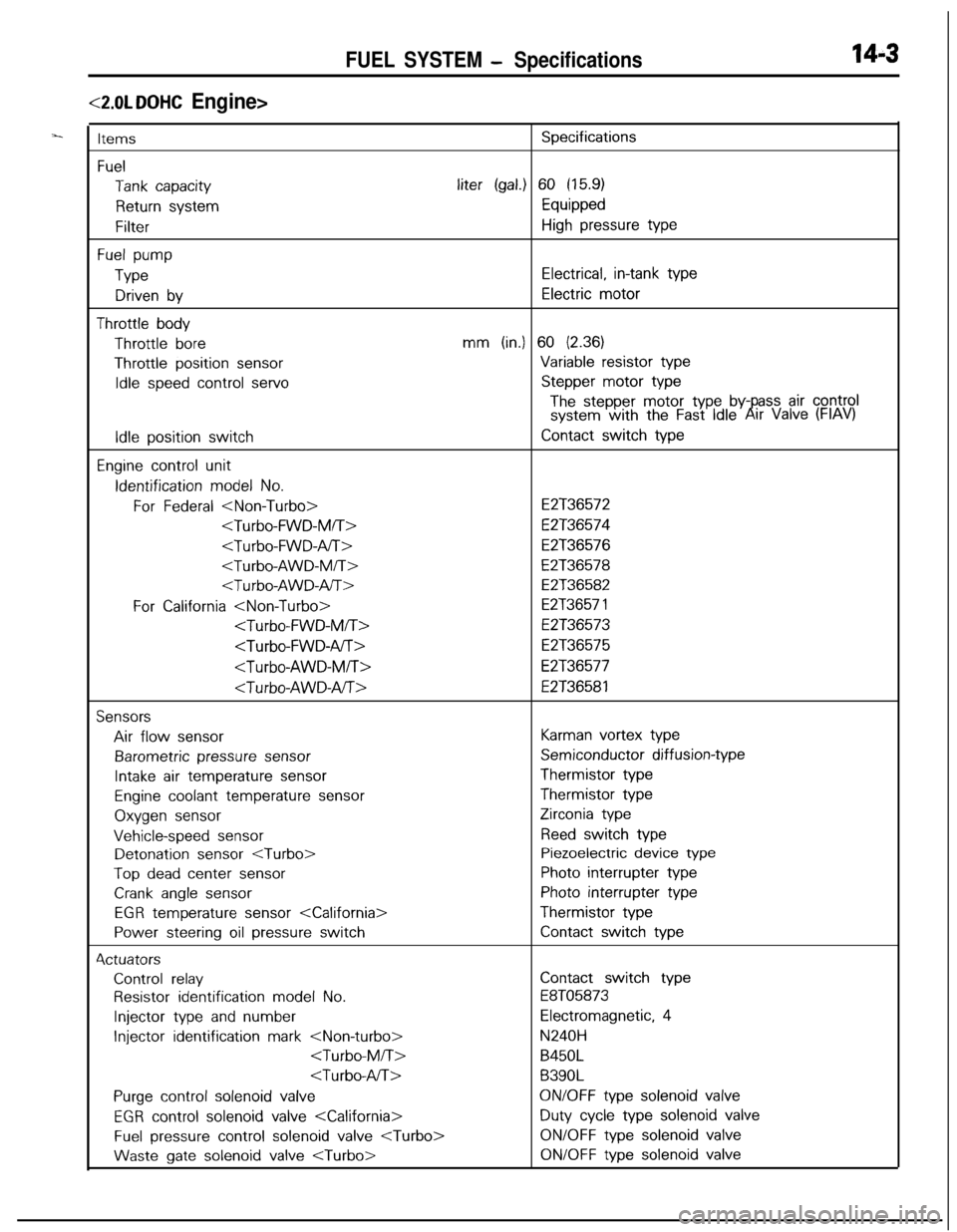
FUEL SYSTEM - Specifications14-3
<2.0L DOHC Engine>
ItemsSpecifications
Fuel
Tank capacityliter (gal.) 60 (15.9)
Return systemEquipped
FilterHigh pressure type
Fuel pump
TypeElectrical, in-tank type
Driven byElectric motor
Throttle bodyThrottle
boremm (in.) 60 (2.36)Throttle position
sensorVariable resistor type
Idle speed control servoStepper motor type
The stepper motor type by- ass air controlsystem with the Fast Idle6!rr Valve (FIAV)
Idle position switchContact switch type
Engine control unitIdentification
model No.
For Federal
E2T36574
E2T36576
E2T36578
E2T36582
For California
E2T36573
E2T36575
E2T36577
E2T36581
SensorsAir flow
sensorKarman vortex type
Barometric pressure sensorSemiconductor diffusion-type
Intake air temperature sensorThermistor type
Engine coolant temperature sensorThermistor type
Oxygen sensorZirconia type
Vehicle-speed sensorReed switch typeDetonation
sensor
Top dead center sensorPhoto interrupter type
Crank angle sensorPhoto interrupter type
EGR temperature sensor
Power steering oil pressure switchContact switch type4ctuators
Control relayContact switch type
Resistor identification model No.E8T05873
Injector type and numberElectromagnetic, 4
Injector identification mark
B450L
B390L
Purge control solenoid valveON/OFF type solenoid valve
EGR control solenoid valve
Fuel pressure control solenoid valve
gate solenoid valve
Page 459 of 1216
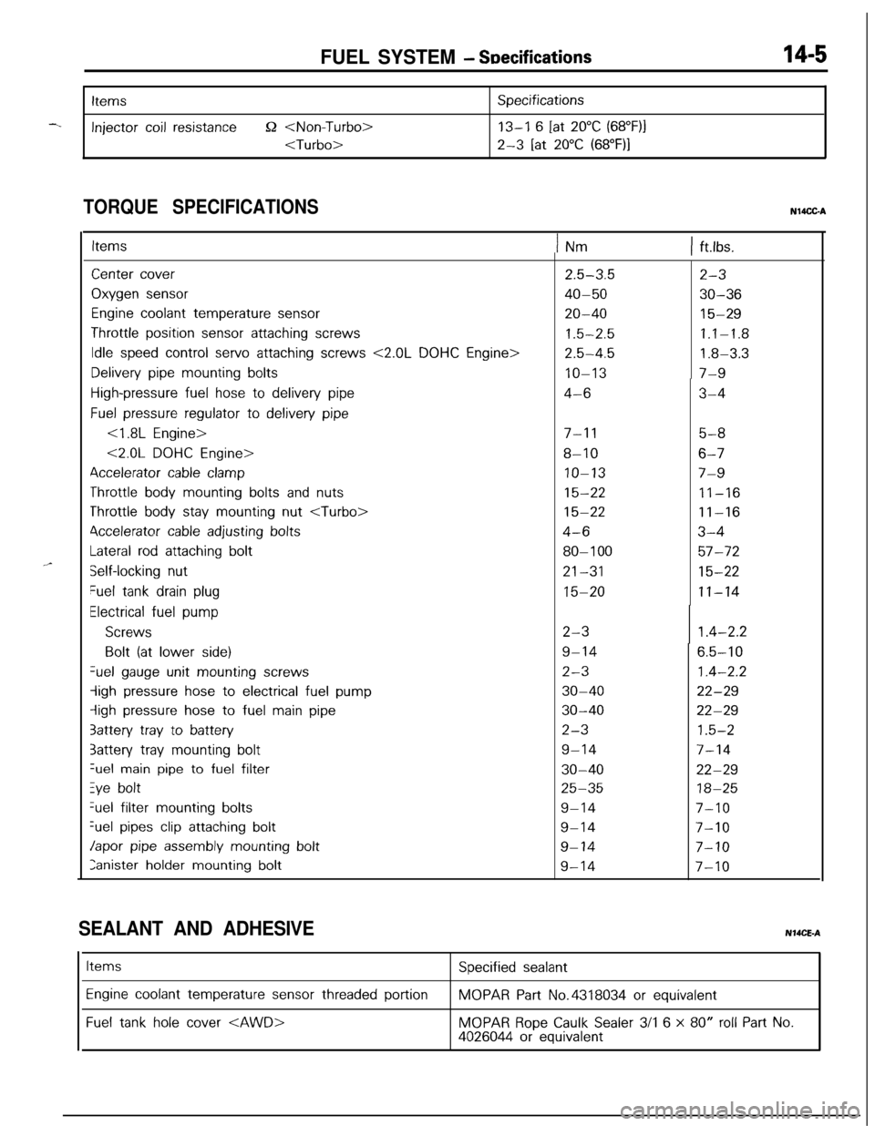
FUEL SYSTEM - SDecifications14-5
-.
Items
Injector coil resistance52
Specifications
13-I 6 [at 20°C (68”F)j
2-3 [at 20°C (68”F)I
TORQUE SPECIFICATIONSN14CC-A
,,-
ItemsINm1 ft.lbs.
Center cover
Oxygen sensor
Engine coolant temperature sensor
Throttle position sensor attaching screws
Idle speed control servo attaching screws <2.0L DOHC Engine>
Delivery pipe mounting bolts
High-pressure fuel hose to delivery pipe
Fuel pressure regulator to delivery pipe
<1.8L Engine>
<2.0L DOHC Engine>
Accelerator cable clamp
Throttle body mounting bolts and nuts
Throttle body stay mounting nut
4ccelerator cable adjusting bolts
Lateral rod attaching bolt
Self-locking nut
Fuel tank drain plug
Electrical fuel pump
Screws
Bolt (at lower side)Gel
gauge unit mounting screws
-ligh pressure hose to electrical fuel pump
iigh pressure hose to fuel main pipe
3attery tray to battery
3attery tray mounting boltGel
main pipe to fuel filter
Zye boltGel filter
mounting bolts
%el pipes clip attaching bolt
Japor pipe assembly mounting bolt
Ianister holder mounting bolt
2.5-3.5
40-50
20-40
1.5-2.5
2.5-4.5
IO-13
4-6
7-l 15-8
8-106-7
IO-137-9
15-2211-16
15-2211-16
4-63-4
80-l 0057-72
21-3115-22
15-2011-14
2-3
9-14
2-3
30-40
30-40
2-3
9-14
30-40
25-35
9-14
9-14
9-14
9-14
2-3
30-36
15-29
1.1-1.8
1.8-3.3
7-9
3-4
1.4-2.2
6.5-10
1.4-2.2
22-29
22-29
1.5-2
7-14
22-29
18-25
7-10
7-10
7-10
7-10
SEALANT AND ADHESIVENMCE-A
Items
Engine coolant temperature sensor threaded portion
Fuel tank hole cover
Specified sealant
MOPAR Part No.4318034 or equivalent
MOPAR Rope Caulk Sealer 3/l 6 x 80” roll Part No.4026044 or equivalent