steering MITSUBISHI ECLIPSE 1991 Service Manual
[x] Cancel search | Manufacturer: MITSUBISHI, Model Year: 1991, Model line: ECLIPSE, Model: MITSUBISHI ECLIPSE 1991Pages: 1216, PDF Size: 67.42 MB
Page 692 of 1216
19-44STEERING - Power Steering Oil Pump
13AO350
13PO159
Punch mark
13c214 I
13W03ECutouts for
dowel pin
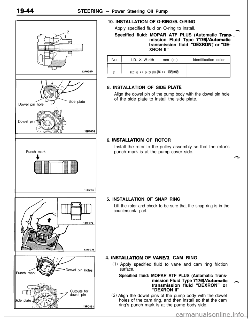
13PO16110. INSTALLATION OF
O-RING/S. O-RING
Apply specified fluid on O-ring to install.
-,Specified fluid: MOPAR ATF PLUS (Automatic
Trans- ”mission Fluid Type 7176)/Automatic
transmission fluid
“DEXRONY or “DE-XRON II”
1 No. 1I.D. x Widthmm (in.)Identification color
I2 1I47.2 16.8x x2.4 2.4(1.86 (.66x x.0945) .0945)- -8. INSTALLATION OF SIDE
PLATE
Align the dowel pin of the pump body with the dowel pin holeof the side plate to install the side plate.
6.
INSTALLATlON OF ROTOR
Install the rotor to the pulley assembly so that the rotor’s
punch mark is at the pump cover side.
s,5. INSTALLATION OF SNAP RING
Lift the rotor and check to be sure that the snap ring is in the
countersunk part.4.
INSTALLATlON OF VANE/3. CAM RING
(I1 Apply specified fluid to vane and cam ring friction
surface.
Specified fluid: MOPAR ATF PLUS (Automatic Trans-mission Fluid Type 7176)IAutomatic
Atransmission fluid “DEXRON” or
“DEXRON II”
(21 Align the dowel pins of the pump body with the dowel
holes of the cam ring, and then install so that the cam
ring’s punch mark is at the pump body side.
Page 693 of 1216
STEERING - Power Steering Oil Pump
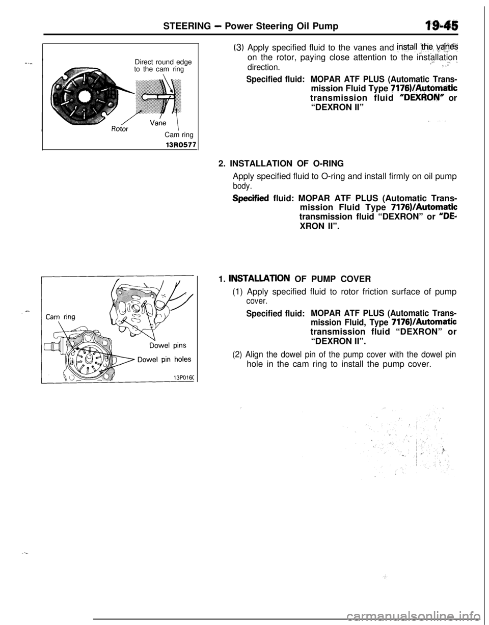
Direct round edge
to the cam
ringCam ring13R0577
(3)Apply specified fluid to the vanes and instafl :lhe yaneson the rotor, paying close attention to the installation
direction.,L.,., ‘,, :.I
Specified fluid:MOPAR ATF PLUS (Automatic Trans-mission Fluid Type
7176)/Auto@tictransmission fluid
“DEXFhOW’ or
“DEXRON II”
2. INSTALLATION OF O-RING
Apply specified fluid to O-ring and install firmly on oil pump
body.
Specified fluid: MOPAR ATF PLUS (Automatic Trans-
mission Fluid Type 7176)/Automatic
transmission fluid “DEXRON” or
“DEdXRON II”.
1.
INSTALLATlON OF PUMP COVER
(1) Apply specified fluid to rotor friction surface of pump
cover.
Specified fluid:MOPAR ATF PLUS (Automatic Trans-
mission Fluid, Type
7176)/Automatictransmission fluid “DEXRON” or
“DEXRON II”.
(2) Align the dowel pin of the pump cover with the dowel pinhole in the cam ring to install the pump cover.
Page 694 of 1216
19-46STEERING - Power Steering Hoses
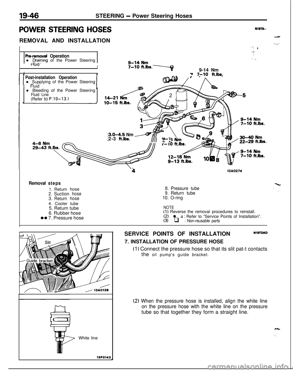
POWER STEERING HOSESREMOVAL AND INSTALLATIONNlSTA-
Pre-removal Operationl C+?ing of the Power Steering
,‘; ,L..,.,.):. ,4-14 NmwaI. . .-...5-10 ft.lbs.7
I9-14 NmI7 7-10 ft.lbs.
Post-installation Operationl Supplying of the Power Steering-.
1 Fluid
l Bleeding of the Power Steering
Fluid Line(Refer to P.19-13.1,621 N/-@b
K
2
3.0-4.5 Nm /2-3 ft.lbs.I/II z-”a.
413A0274
Removal steps
1.Returnhose2.Suctionhose
3.Returnhose4. Cooler tube
5. Return tube
6. Rubber hose
.a 7. Pressure hose
8.Pressure tube9.Return tube
10.O-ring
NOTE(1) Reverse the removal procedures to reinstall.
(2) l a : Refer to “Service Points of Installation”.(3) q : Non-reusable partsWhite lineUP0143SERVICE POINTS OF INSTALLATION
NlSTDAD7. INSTALLATION OF PRESSURE HOSE
(1) Connect the pressure hose so that its slit pat-t contacts
the oil pump’s guide bracket.
(2) When the pressure hose is installed, align the white line
on the pressure hose with the white line on the pressuretube so that together they form a straight line.
Page 912 of 1216
2l-218AUTOMATIC TRANSAXLE - Transaxle Control
724
169-14
Nm7-10 ftlbs.7
\\4-6 Nm3-4 ft.lbs.3-4
ft.lbs.
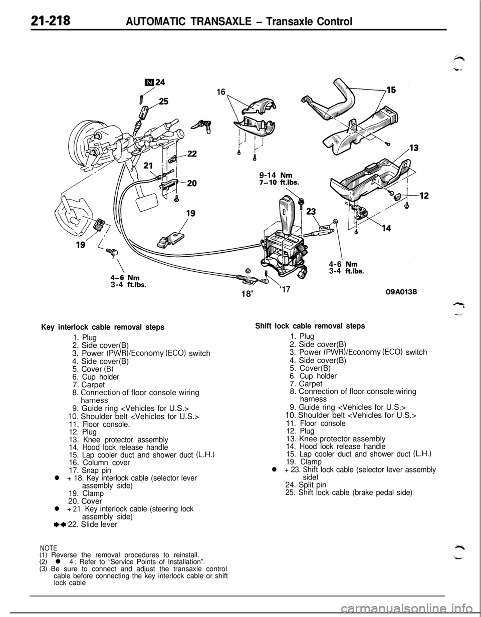
Key interlock cable removal steps
1. Plug2. Side cover(B)
3. Power
(PWR)/Economy (ECO) switch
4. Side cover(B)
5. Cover
(B)6. Cup holder7. Carpet
8.
;ir;eystion of floor console wiring
9. Guide ring
10. Shoulder belt
12. Plug
13. Knee protector assembly
14. Hood lock release handle
15. Lap cooler duct and shower duct
(L.H.)16. Column cover
17. Snap pin
l + 18. Key interlock cable (selector lever
assembly side)
19. Clamp20. Cover
l + 21, Key interlock cable (steering lock
assembly side)
e+ 22. Slide lever
NOTE(I) Reverse the removal procedures to reinstall.(2) l 4 : Refer to “Service Points of Installation”.(3) Be sure to connect and adjust the transaxle control
cable before connecting the key interlock cable or shift
lock cable18'
‘1709A0138
Shift lock cable removal steps
1. Plug2. Side cover(B)
3. Power
(PWR)/Economv (EC01 switch
4. Side cover(B)
’5. Cover(B)
6. Cup holder7. Carpet
8. Connection of floor console wiring
harness9. Guide ring
10. Shoulder belt
11. Floor console
12. Plug13. Knee protector assembly
14. Hood lock release handle
15. Lap cooler duct and shower duct (L.H.)19. Clamp
l + 23. :izs lock cable (selector lever assembly24. Split pin
25. Shift lock cable (brake pedal side)
Page 914 of 1216
AUTOMATIC TRANSAXLE - Transaxle Control
:lemotJnt
\\ \09R0058
09AO143
/’
\
’ CoverCoverKey interlock cableOSA0125
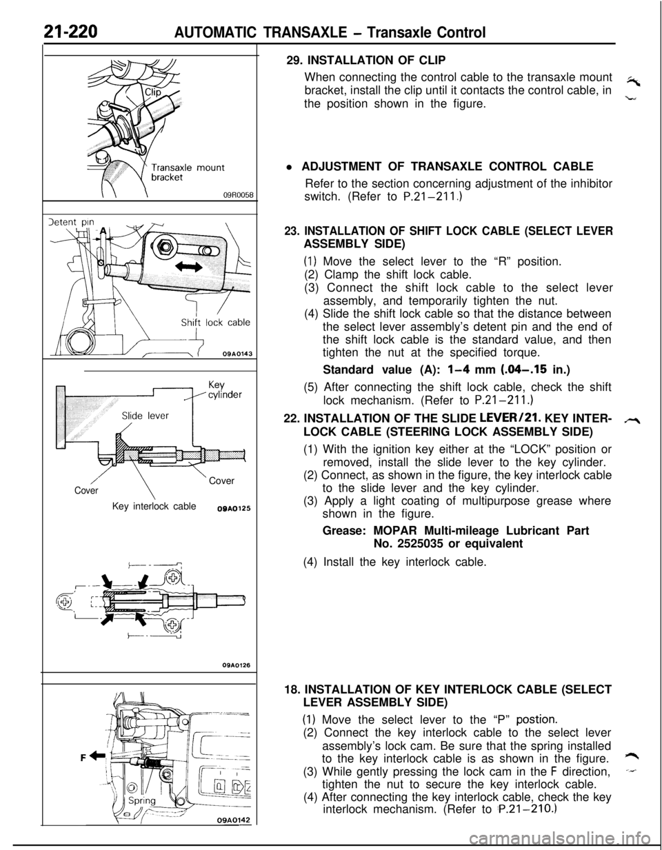
OSAO12629. INSTALLATION OF CLIP
When connecting the control cable to the transaxle mount
,-bracket, install the clip until it contacts the control cable, in
the position shown in the figure.
,”l ADJUSTMENT OF TRANSAXLE CONTROL CABLE
Refer to the section concerning adjustment of the inhibitor
switch. (Refer to P.21-211.)
23. INSTALLATION OF SHIFT LOCK CABLE (SELECT LEVERASSEMBLY SIDE)
(1) Move the select lever to the “R” position.
(2) Clamp the shift lock cable.
(3) Connect the shift lock cable to the select lever
assembly, and temporarily tighten the nut.
(4) Slide the shift lock cable so that the distance between
the select lever assembly’s detent pin and the end of
the shift lock cable is the standard value, and then
tighten the nut at the specified torque.
Standard value (A):
l-4 mm (.04-.I5 in.)
(5) After connecting the shift lock cable, check the shift
lock mechanism. (Refer to P.21-211.)
22. INSTALLATION OF THE SLIDE LEVERI21. KEY INTER-
LOCK CABLE (STEERING LOCK ASSEMBLY SIDE)
(1) With the ignition key either at the “LOCK” position or
removed, install the slide lever to the key cylinder.
(2) Connect, as shown in the figure, the key interlock cable
to the slide lever and the key cylinder.
(3) Apply a light coating of multipurpose grease where
shown in the figure.
Grease: MOPAR Multi-mileage Lubricant Part
No. 2525035 or equivalent
(4) Install the key interlock cable.
18. INSTALLATION OF KEY INTERLOCK CABLE (SELECT
LEVER ASSEMBLY SIDE)
(1) Move the select lever to the “P” postion.(2) Connect the key interlock cable to the select lever
assembly’s lock cam. Be sure that the spring installed
to the key interlock cable is as shown in the figure.
*(3) While gently pressing the lock cam in the
F direction,-tighten the nut to secure the key interlock cable.
(4) After connecting the key interlock cable, check the key
interlock mechanism. (Refer to ‘P.21-210.)
Page 1048 of 1216
23-4BODY - SDecifications
Items
Nmft.lbs.
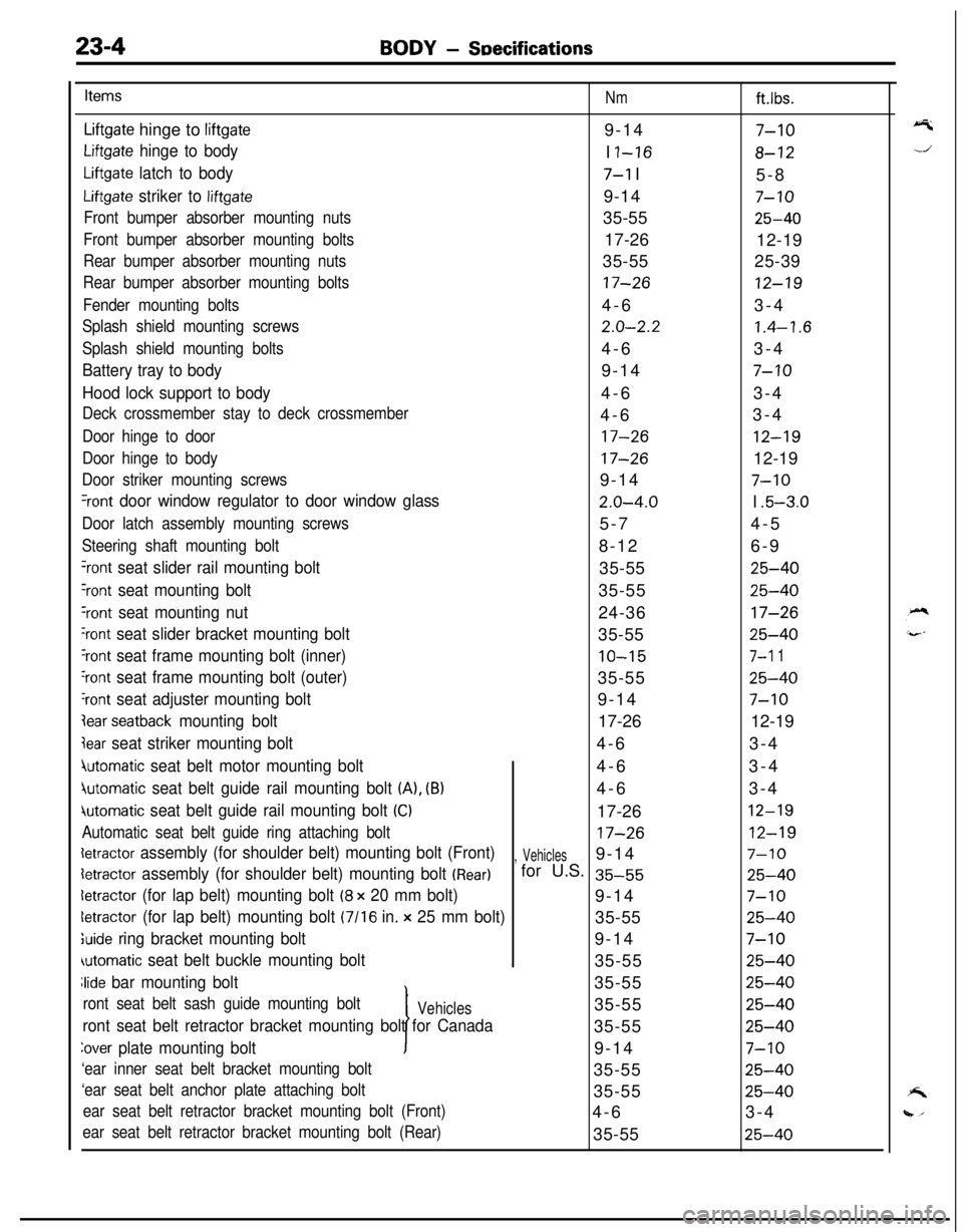
Liftgate hinge to liftgate9-147-10
Liftgate hinge to bodyI I-168-12
Liftgate latch to body7-l I
5-8
Liftgate striker to liftgate9-147-10
Front bumper absorber mounting nuts35-5525-40
Front bumper absorber mounting bolts17-26
12-19
Rear bumper absorber mounting nuts35-5525-39
Rear bumper absorber mounting bolts17-2612-19
Fender mounting bolts4-63-4
Splash shield mounting screws2.0-2.21.4-1.6
Splash shield mounting bolts4-63-4
Battery tray to body9-147-10
Hood lock support to body4-63-4
Deck crossmember stay to deck crossmember4-63-4
Door hinge to door17-2612-19
Door hinge to body17-2612-19
Door striker mounting screws9-147-10
%ont door window regulator to door window glass2.0-4.0I .5-3.0
Door latch assembly mounting screws5-74-5
Steering shaft mounting bolt8-126-9
‘rant seat slider rail mounting bolt35-5525-40
Yont seat mounting bolt35-5525-40
‘rant seat mounting nut24-3617-26
‘rant seat slider bracket mounting bolt35-5525-40
‘rant seat frame mounting bolt (inner)10-157-l 1
‘rant seat frame mounting bolt (outer)35-5525-40
‘rant seat adjuster mounting bolt9-147-10
lear seatback mounting bolt17-2612-19
jear seat striker mounting bolt4-63-4
4utomatic seat belt motor mounting bolt4-63-4
jutomatic seat belt guide rail mounting bolt (A), (B)4-63-4
iutomatic seat belt guide rail mounting bolt (Cl17-2612-19
Automatic seat belt guide ring attaching bolt17-2612-19
detractor assembly (for shoulder belt) mounting bolt (Front), Vehicles9-147-10
detractor assembly (for shoulder belt) mounting bolt (Rear)for U.S. 35-5525-40
detractor (for lap belt) mounting bolt (8 x 20 mm bolt)9-147-10
letractor (for lap belt) mounting bolt (7116 in. x 25 mm bolt)35-5525-40
;uide ring bracket mounting bolt9-147-10
automatic seat belt buckle mounting bolt35-5525-40
Jide bar mounting bolt
I35-55
25-40
ront seat belt sash guide mounting boltVehicles35-5525-40
ront seat belt retractor bracket mounting bolt for Canada35-5525-40
Zover plate mounting bolt9-147-10
‘ear inner seat belt bracket mounting bolt35-5525-40
‘ear seat belt anchor plate attaching bolt35-5525-40
ear seat belt retractor bracket mounting bolt (Front)4-63-4
ear seat belt retractor bracket mounting bolt (Rear)35-5525-40
Page 1124 of 1216
23-80BODY - Instrument Panel
REMOVAL AND INSTALLATION
-?7
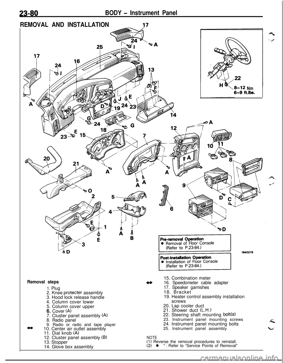
Removal steps
1. Plug2. Knee protecter assembly
3. Hood lock release handle
4. Column cover lower
5. Column cover upper
6. Cover
(A)7. Cluster panel assembly (A)8. Radio panel9. Radio or radio and tape player
10. Center air outlet assembly
11. Dial knob (A)12. Cluster panel assembly (B)13. Stopper
14. Glove box assembly
Nm6-9 ft.lk.15. Combination meter
16. Speedometer cable adapter
17. Speaker garnishes18. Bracket
19. Heater control assembly installation
screws
20. Lap cooler duct
21. Shower duct (L.H.122. Steering shaft mounting bolt(s)23. Instrument panel mounting screws
24. Instrument panel mounting bolts
25. Instrument panel assembly
NOTE(1) Reverse the removal procedures to reinstall.(2) l * : Refer to “Service Points of Removal”
Page 1168 of 1216
24-24 HEATERS AND AIR CONDITIONING - Service Adjustment Procedures
COMPRESSOR NOISENUFIABWhen investigating an air conditioning related noise, you must
first know the conditions when the noise occurs. These
conditions are: weather, vehicle speed, in gear or neutral,
engine temperature or any other special conditions.
Noises that develop during air conditioning operation can oftenbe misleading. For example: what sounds like a failed front
bearing or connecting rod, may be caused by loose bolts, nuts,mounting brackets, or a loose clutch assembly. Verify acces-
sory drive belt tension (power steering, or alternator).
Improper accessory drive belt tension can cause a misleading
noise when the compressor is engaged and little or no noise
when the compressor is disengaged.
Drive belts are speed sensitive. That is, at different engine
speeds, and depending upon belt tension, belts can develop
unusual noises that are often mistaken for mechanical prob-
lems within the compressor.
Adjustment Procedures
(1) Select a quiet area for testing. Duplicate conditions as
much as possible. Switch compressor on and off several
times to clearly identify compressor noise.
To duplicate high ambient conditions (high head pressure),restrict air flow through condenser. Install manifold gauge
set to make sure discharge pressure doesn’t exceed 2,070
kPa (300 psi).
(2) Tighten all compressor mounting bolts, clutch mounting
bolt, and compressor drive belt. Check to assure clutch coilis tight (no rotation or wobble).
(3) Check refrigerant hoses for rubbing or interference that cancause unusual noises.
(4) Check refrigerant charge (See “Charging the System”).
(5) Recheck compressor noise as in Step 1.
(6) If noise still exists, loosen compressor mounting bolts and
retorque. Repeat Step 1.
(7) If noise continues, replace compressor and repeat Step 1.
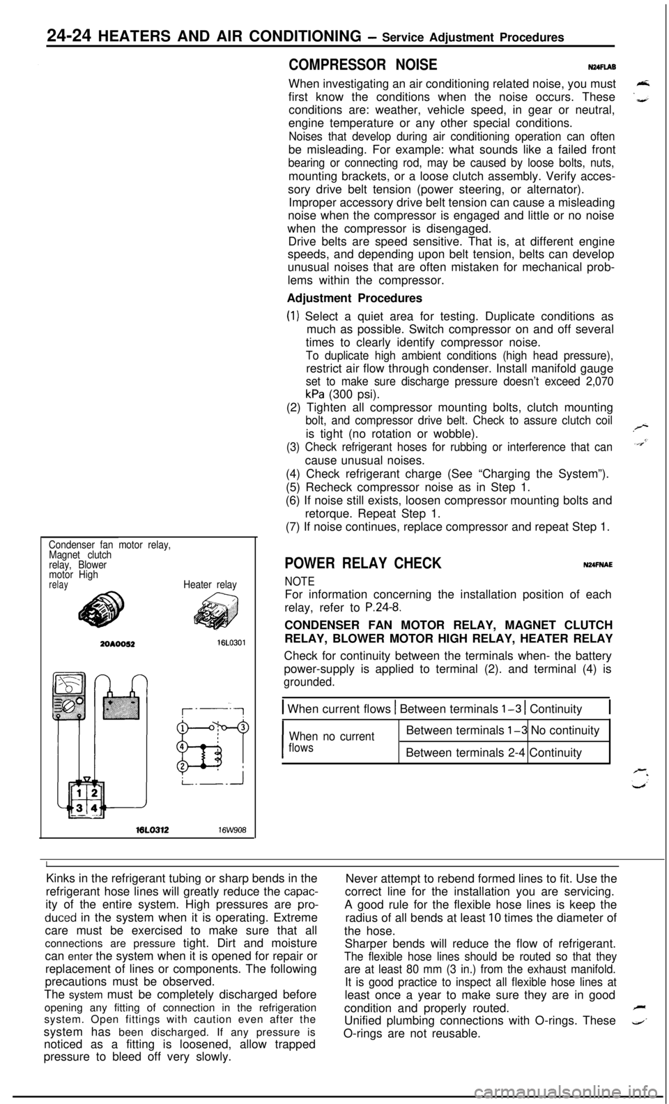
Condenser fan motor relay,
Magnet clutch
relay, Blower
motor High
relayHeater relayML0312
16W908
POWER RELAY CHECKNUFNAE
NOTEFor information concerning the installation position of each
relay, refer to
P.24-8.CONDENSER FAN MOTOR RELAY, MAGNET CLUTCH
RELAY, BLOWER MOTOR HIGH RELAY, HEATER RELAY
Check for continuity between the terminals when- the battery
power-supply is applied to terminal (2). and terminal (4) is
grounded.
1 When current flows 1 Between terminals l-3 1 Continuity1
I
When no currentBetween terminals l-3 No continuity
flowsBetween terminals 2-4 Continuity
IKinks in the refrigerant tubing or sharp bends in the
Never attempt to rebend formed lines to fit. Use the
refrigerant hose lines will greatly reduce the
capac-correct line for the installation you are servicing.
ity of the entire system. High pressures are
pro-A good rule for the flexible hose lines is keep the
duced in the system when it is operating. Extreme
radius of all bends at least 10 times the diameter of
care must be exercised to make sure that all
the hose.
connections are pressure tight. Dirt and moisture
Sharper bends will reduce the flow of refrigerant.
can enter the system when it is opened for repair or
The flexible hose lines should be routed so that theyreplacement of lines or components. The following
are at least 80 mm (3 in.) from the exhaust manifold.precautions must be observed.
It is good practice to inspect all flexible hose lines atThe system must be completely discharged before
least once a year to make sure they are in good
opening any fitting of connection in the refrigeration
condition and properly routed.
Fsystem. Open fittings with caution even after the
Unified plumbing connections with O-rings. These
4’system has been discharged. If any pressure is
noticed as a fitting is loosened, allow trappedO-rings are not reusable.
pressure to bleed off very slowly.
Page 1169 of 1216
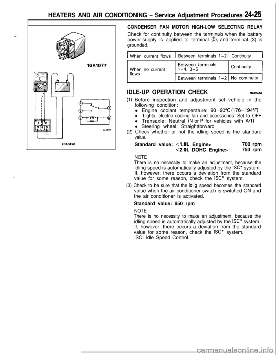
HEATERS AND AIR CONDITIONING - Service Adjustment Procedures 24-25
16A1077
20AO499
CONDENSER FAN MOTOR HIGH-LOW SELECTING RELAYCheck for continuity between the
term,inals when the battery
power-supply is applied to terminal
(5), and terminal (3) is
grounded.
IWhen current flows1 Between terminals l-2 1 Continuity1When no current
flows
IDLE-UP OPERATION CHECKN24FoAA
(I) Before inspection and adjustment set vehicle in the
following condition:
l Engine coolant temperature:
80-90°C (176-194°F)
lLights, electric cooling fan and accessories: Set to OFFl Transaxle: Neutral
(N or P for vehicles with A/T)l Steering wheel: Straightforward
(2) Check whether or not the idling speed is the standard
value.Standard value:
4.8L Engine>700 rpm
<2.0L DOHC Engine>750 rpm
NOTE
There is no necessity to make an adjustment, because theidling speed is automatically adjusted by the
ISC” system.
If, however, there occurs a deviation from the standard
value for some reason, check the
ISC” system.
(3) Check to be sure that the idlig speed becomes the standardvalue when the air conditioner switch is switched ON and
the air conditioner is activated.
Standard value: 850 rpm
NOTE
There is no necessity to make an adjustment, because theidling speed is automatically adjusted by the
ISC” system.
If, however, there occurs a deviation from the standard
value for some reason, check the
ISC” system.
ISC: Idle Speed Control