Rear suspension MITSUBISHI ECLIPSE 1991 Service Manual
[x] Cancel search | Manufacturer: MITSUBISHI, Model Year: 1991, Model line: ECLIPSE, Model: MITSUBISHI ECLIPSE 1991Pages: 1216, PDF Size: 67.42 MB
Page 1 of 1216
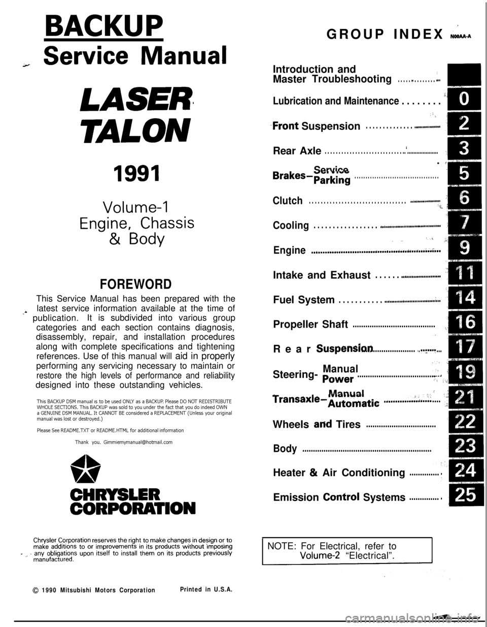
BACKUPGROUP INDEX &ma
;r Service Manual
LASER
TALON
1991
Volume-l
Engine, Chassis
& Body
FOREWORDThis Service Manual has been prepared with the
latest service information available at the time of
‘* publication.It is subdivided into various group
categories and each section contains diagnosis,
disassembly, repair, and installation procedures
along with complete specifications and tightening
references. Use of this manual will aid in properly
performing any servicing necessary to maintain or
restore the high levels of performance and reliabilitydesigned into these outstanding vehicles.
This BACKUP DSM manual IS to be used ONLY as a BACKUP. Please DO NOT REDISTRIBUTEWHOLE SECTIONS. This BACKUP was sold to you under the fact that you do indeed OWNa GENUINE DSM MANUAL. It CANNOT BE considered a REPLACEMENT (Unless your originalmanual was lost or destroyed.)Please See
README.N or README.HTML for additional information
Thank you. G~mm~emymanual@hotma~l.com
1,
wA
CHRYSLER
CORPORATION
Chrysler Corporation reserves the right to make changes in design 0’: tomake additions to or improvements in its products without lmqoslngd ., . any obligations upon itself to install them on its products previouslymanufactured.
0 1990 Mitsubishi Motors CorporationPrinted in U.S.A.Introduction and
Master
Troubleshooting. . . . . .,. . . . . . . . . r...m,
Lubrication and Maintenance . . . . . . . . ‘-0‘8
; “. i,
.Front Suspension. . . . . . . . . . . . . . ..*............d...Rear Axle
. . . . . . . . . . . . . . . . . . . . . . . . . . . . ..‘.....................
/
ServiceBrakes-Parking. . . . . . . . . . . . . . . . . . . . . . . . . . . . . . . . . . . . . .
Clutch. . . . . . . . . . . . . . . . . . . . . . . . . . . . . . . . . ..~......................‘t.
Cooling. . . . . . . . . . . . . . . . . ..i....................................
,., .‘,-,
Engine..i....~....r...............~....~.*,.~.~.~,‘~~...;..~~..Intake and Exhaust
. . . . . . ..L....................Fuel System
. . . . . . . . . . . ..ti.......r................~...Propeller Shaft
.......................................IRear
Suspensiori.............................y.f...
ManualSteering- Power.....................................Manual
I
transaxle-Automatic .............:;i...,;.....;Wheels
and Tires.................................
Body.............................................................Heater & Air Conditioning
..............Emission
Contr6l Systems..............
INOTE: For Electrical, refer toVolume-2 “Electrical”.
Page 20 of 1216
20INTRODUCTION AND MASTER TROUBLESHOOTING - Towing and Hoisting
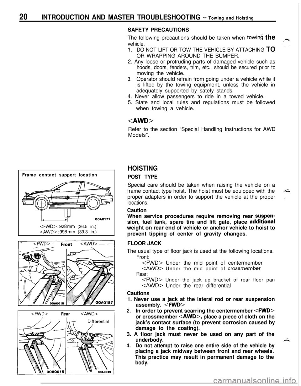
Frame contact support location
OOAOI 71
I
The following precautions should be taken when
towin the
vehicle.
1.DO NOT LIFT OR TOW THE VEHICLE BY ATTACHING TOOR WRAPPING AROUND THE BUMPER.
2. Any loose or protruding parts of damaged vehicle such as
hoods, doors, fenders, trim, etc., should be secured prior tomoving the vehicle.
3.Operator should refrain from going under a vehicle while it
is lifted by the towing equipment, unless the vehicle in
adequately supported by satefy stands.
4. Never allow passengers to ride in a towed vehicle.
5. State and local rules and regulations must be followed
when towing a vehicle.
Refer to the section “Special Handling Instructions for AWD
Models”.
HOISTING
POST TYPESpecial care should be taken when raising the vehicle on a
frame contact type hoist. The hoist must be equipped with the
proper adapters in order to support the vehicle at the proper
locations.Caution
When service procedures require removing rear sutpen-
sion, fuel tank, spare tire and lift gate, place addmonal
weight on rear end of vehicle or anchor vehicle to hoist to
prevent tipping of center of gravity changes.
FLOOR JACK
The usual type of floor jack is used at the following locations.
Front:
Rear:
Cautions
1. Never use a jack at the lateral rod or rear suspension
assembly.
2.In order to prevent scarring the centermember
jack’s contact surface (to prevent corrosion caused by
damage to the coating).
3. A floor jack must never be used on any part of the
underbody.
4.Do not attempt to raise one entire side of the vehicle byplacing a jack midway between front and rear wheels.
This practice may result in permanent damage to the
body.
Page 26 of 1216
26INTRODUCTION AND MASTER TROUBLESHOOTING - :;:%:a=and
Items
Chassis
TireFront suspension
TypeRear suspension
We
Brake
Type
SteeringGear typeFront
RearGear ratio
Fuel tank
Capacityliters (gals.)
1.8L Engine
“Medium”Pl85/70R14
PI 85/70Rl4
Independent
strut
Independentstrut
3l\Fk Torsion&k-k Torsion
Disc
DiscDisc
Disc
Rack and
pinion
03
Rack and
pinion
cn60 (16)
60
(16)
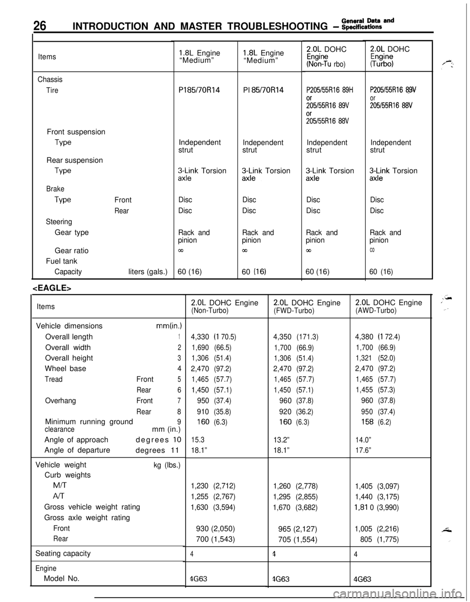
ItemsVehicle dimensions
mm(in.)Overall length
1Overall width
2Overall height
3Wheel base
4
TreadFront5
Rear6
OverhangFront7
Rear8Minimum running ground
9
clearancemm (in.)
Angle of approachdegrees
10Angle of departure
degrees 11
Vehicle weight
kg (Ibs.)Curb weightsMiT
Al-rGross vehicle weight rating
Gross axle weight rating
Front
RearSeating capacity
EngineModel No.
1.8L Engine
“Medium”2.0L DOHC
Kr%n?u rbo)
P205/55Rl6 89H
;;5/55R16 89V%55R16
88V
Independentstrut
zx;;k Torsion
Disc
Disc
Rack and
pinion
co60 (16)
2.0L DOHC
#b”;
P205/55Rl6 89
or
205155R16 88V
Independentstrut
3Lnk Torsion
Disc
Disc
Rack and
pinion
co
60 (16)
2.0L DOHC Engine(Non-Turbo)
4,330(I 70.5)
1,690(66.5)
1,306(51.4)
2,470(97.2)
1,465(57.7)
1,450(57.1)
950(37.4)
910(35.8)
160(6.3)
15.3
18.1”
1,230 (2,712)
1,255 (2,767)
1,630 (3,594)930 (2,050)
700 (1,543)
4
4G63
2.0L DOHC Engine
(FWD-Turbo)
4,350(171.3)
1,700(66.9)
1,306(51.4)
2,470(97.2)
1,465(57.7)
1,450(57.1)
960(37.8)
920(36.2)
160(6.3)
13.2”
18.1”
1,260 (2,778)
1,295 (2,855)
1,670 (3,682)965 (2,127)
705 (1,554)
1
4G63
2.0L DOHC Engine
(AWD-Turbo)
4,380(I 72.4)
1,700(66.9)
1,321(52.0)
2,470(97.2)
1,465(57.7)
1,455(57.3)
960(37.8)
950(37.4)
158(6.2)
14.0”
17.6”
1,405 (3,097)
1,440 (3,175)
I,81 0 (3,990)
1,005 (2,216)
805 (1,775)
4
4G63
Page 27 of 1216
INTRODUCTION AND MASTER TROUBLESHOOTING - f~EEaZ% acld27
=r
9..
Items
TransaxleModel No.
Manual transaxle
Automatic transaxle
Clutch
Type
Chassis
TireFront suspension
TypeRear suspension
Type
Brake
Type
SteeringGear type
Gear ratio
Fuel tank
Capacity
2.0L DOHC Engine2.0L DOHC Engine2.0L DOHC Engine
(Non-Turbo)(FWD-Turbo)(AWD-Turbo)
F5M22F5M33W5M33
F4A22F4A33W4A33Dry-single disc
Dry-single discDry-single disc& diaphragm spring& diaphragm spring& diaphragm spring
P205/55R16 89HP205155R16 89VP205/55R16 89Vor 205/55R16 89Vor 205/55R16 88Vor 205/55R16 88Vor 205/55R16 88VIndependent strut
Independent strutIndependent strut
3-Link Torsion axle3-Link Torsion axleDouble wishbone
Front
Disc
DiscDisc
RearDisc
DiscDiscRack and pinion
Rack and pinionRack
,and pinion
03coccliters (gals.) 60 (16)
60 (16)60 (16)
)
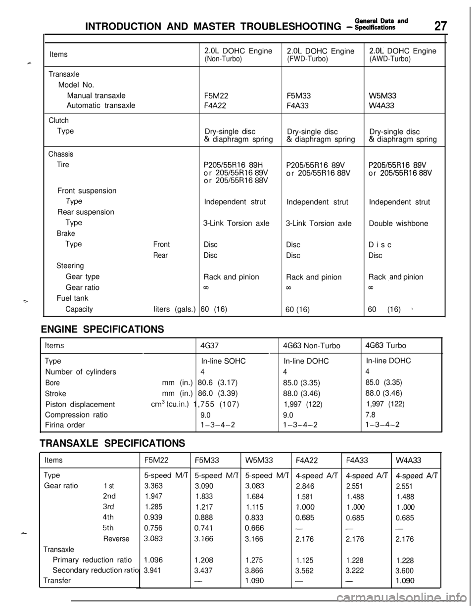
ENGINE SPECIFICATIONS
Items4G374G63 Non-Turbo4G63 Turbo
TypeIn-line SOHCIn-line DOHCIn-line DOHC
Number of cylinders
444
Boremm (in.) 80.6 (3.17)
85.0 (3.35)85.0 (3.35)
Strokemm (in.) 86.0 (3.39)
88.0 (3.46)88.0 (3.46)
Piston displacement
cm3 (cu.in.) 1,755 (107)1,997 (122)1,997 (122)Compression ratio
9.09.07.8Firina order
1-3-4-21-3-4-21-3-4-2
TRANSAXLE SPECIFICATIONS
ItemsF5M22F5M33W5M33F4A22F4A33W4A33
TypeGear ratio
1 st
2nd
3rd
4th
5th
Reverse
TransaxlePrimary reduction ratio
Secondary reduction
ratio
Transfer
5-speed M/T5-speed M/T
3.363
3.090
1.947
1.833
1.285
1.217
0.939
0.888
0.756
0.741
3.0833.166
5speed M/T4-speed A/T4-speed AIT
3.083
2.8462.551
1.6841.5811.488
1.115
1.0001 .ooo
0.8330.6850.685
0.666--
3.166
2.1762.176
Qspeed AIT
2.551
1.488
1 .ooo
0.685
-
2.176
1.096
3.9411.2081.275
1.1251.2281.228
3.4373.866
3.5623.222
3.600
-1.090--1.090
Page 32 of 1216
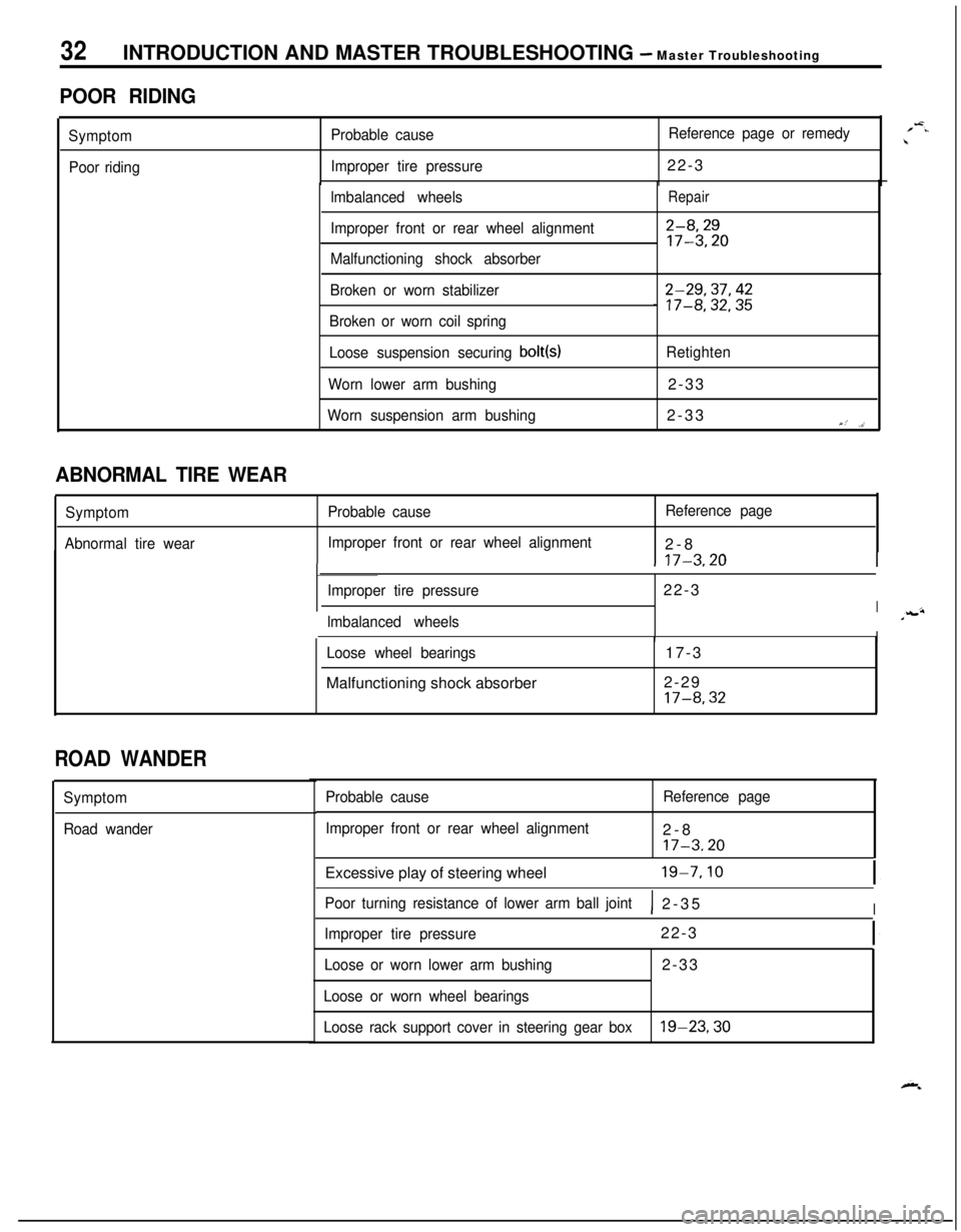
32INTRODUCTION AND MASTER TROUBLESHOOTING - Master Troubleshooting
POOR RIDING
Symptom
Poor ridingProbable causeReference page or remedy
Improper tire pressure22-3
lmbalanced wheels
Improper front or rear wheel alignment
Malfunctioning shock absorberRepair
2-8,2917-3.20
Broken or worn stabilizer
Broken or worn coil spring2-29,37,42_ 17-8,32,35
Loose suspension securing bolt(s)Retighten
Worn lower arm bushing2-33
Worn suspension arm bushing2-33Y,’ ,>’
1 17-3.20I
ABNORMAL TIRE WEAR
Symptom
Abnormal tire wearProbable causeReference page
Improper front or rear wheel alignment2-8
Improper tire pressure22-3
Ilmbalanced wheelsIILoose wheel bearingsMalfunctioning shock absorber17-3
2-29
17-8,32
ROAD WANDER
Symptom
Road wanderProbable cause
Improper front or rear wheel alignmentReference page2-8
17-3.20Excessive play of steering wheel
19-7.10
Poor turning resistance of lower arm ball joint1 2-35I
Improper tire pressure22-3
Loose or worn lower arm bushing2-33
Loose or worn wheel bearings
Loose rack support cover in steering gear box
19-23,30
/-=..\
Page 53 of 1216
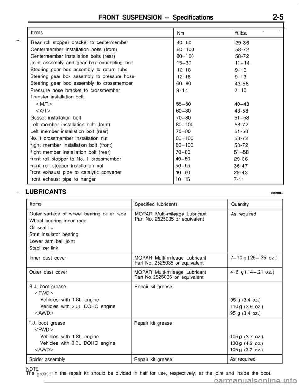
FRONT SUSPENSION - Specifications2-5Items
Rear roll stopper bracket to centermember
Centermember installation bolts (front)
Centermember installation bolts (rear)
Joint assembly and gear box connecting bolt
Steering gear box assembly to return tube
Steering gear box assembly to pressure hose
Steering gear box assembly to crossmember
Pressure hose bracket to crossmember
Transfer installation bolt
Nmftlbs. I’, ‘,
40-5029-36
80-10058-72
80-I 0058-72
15-20II-1412-18
9-13
12-189-13
60-8043-58
9-14
7-10
55-6040-43
Gusset installation bolt
70-8051-58Left member installation bolt (front)
80-10058-72
Left member installation bolt (rear)
70-8051-58
Vo. 1 crossmember installation nut80-10058-72qight member installation bolt (front)
80-10058-72?ight member installation bolt (rear)
70-8051-58
+ont roll stopper to No. 1 crossmember40-5029-36
?ont roll stopper installation nut50-6536-47
Iront exhaust pipe to catalytic converter40-6029-43
‘rant exhaust pipe to hangerIO-157-11
‘-. LUBRICANTSNO2CD--
ItemsSpecified lubricantsQuantity
Outer surface of wheel bearing outer race
MOPAR Multi-mileage LubricantAs required
Wheel bearing inner racePart No. 2525035 or equivalent
Oil seal lip
Strut insulator bearing
Lower arm ball joint
Stabilizer link
Inner dust coverMOPAR Multi-mileage Lubricant
Part No. 2525035 or equivalent
7-10 g (.25-.35 oz.)
Outer dust cover
MOPAR Multi-mileage Lubricant
Part
No.2525035 or equivalent4-6
g (.14-.21 oz.)
B.J. boot grease
Repair kit grease
1.8L engine
95 g (3.4 oz.)
Vehicles with
2.0L DOHC engine110 g (3.9 oz.)
T.J. boot grease
Repair kit grease
1.8L engine105 g (3.7 oz.)
Vehicles with
2.0L DOHC engine120 g (4.2 oz.)
Spider assemblyRepair kit greaseAs required
NOTEThe grease in the repair kit should be divided in half for use, respectively, at the joint and inside the boot.
Page 56 of 1216
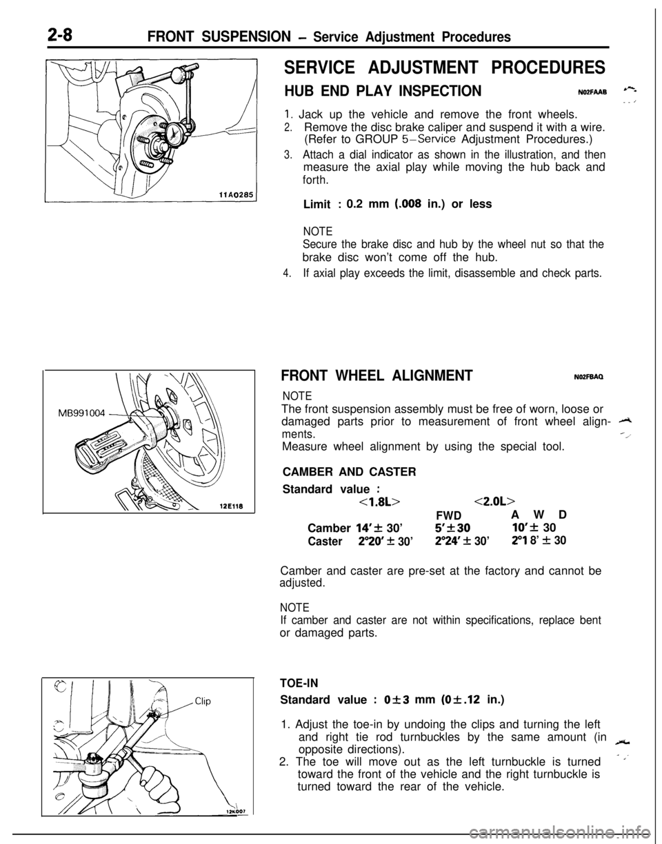
2-8FRONT SUSPENSION - Service Adjustment Procedures
SERVICE ADJUSTMENT PROCEDURES
HUB END PLAY INSPECTIONNO2FAAB --- ’
1. Jack up the vehicle and remove the front wheels.
2.Remove the disc brake caliper and suspend it with a wire.
(Refer to GROUP
5-Service Adjustment Procedures.)
3.Attach a dial indicator as shown in the illustration, and thenmeasure the axial play while moving the hub back and
forth.Limit
: 0.2 mm (.008 in.) or less
NOTE
Secure the brake disc and hub by the wheel nut so that thebrake disc won’t come off the hub.
4.If axial play exceeds the limit, disassemble and check parts.
FRONT WHEEL ALIGNMENTNOZFBAQ
NOTEThe front suspension assembly must be free of worn, loose or
damaged parts prior to measurement of front wheel align-
A
ments.--l
Measure wheel alignment by using the special tool.
CAMBER AND CASTER
Standard value
:
<1.8L><2.0L>
FWDAWD
Camber
14’+ 30’5’k3010’f 30
Caster250 + 30’2”24’ + 30’29 8’ f 30Camber and caster are pre-set at the factory and cannot be
adjusted.
NOTE
If camber and caster are not within specifications, replace bentor damaged parts.
TOE-INStandard value
:Of3 mm (Of.12 in.)
1. Adjust the toe-in by undoing the clips and turning the left
and right tie rod turnbuckles by the same amount (in
-opposite directions).
2. The toe will move out as the left turnbuckle is turned
- ,’toward the front of the vehicle and the right turnbuckle is
turned toward the rear of the vehicle.
Page 75 of 1216

FRONT SUSPENSION - Drive Shaft2-27llAOO91
M B990938
11L0010Inner dust seal
Outer dust seal
llLOO12nner dust seal,
p MB990938
11 LOO09Outer dust seal10. INSTALLATION OF CENTER BEARING
(1) Apply multipurpose grease to the center bearing and
inside the center bearing bracket.
Grease: MOPAR Multi-mileage Lubricant
Part No.2525035 or equivalent
(2) Use the special tools to press-fit the center bearing into
the center bearing bracket.
9./8. INSTALLATION OF DUST SEALS
(1) Apply multipurpose grease to the rear surfaces of all
dust seals.
Grease: MOPAR Multi-mileage Lubricant
Part No.2525035 or equivalent
Inner dust seal
7-10 g (.25-.35 oz)Outer dust seal4-6
g (.14-.21 oz)(2) Use the special tools to install the dust seal so that its
surface runs even with that of the center bearing
bracket.(3) Apply multipurpose grease to the lip of each dust seal.
Grease: MOPAR
Multi-mi!eage Lubricant
Part No.2525035 or equivalent
NOTE
When applying grease, make sure that it does not adhere toanything outside the lip.
Page 85 of 1216
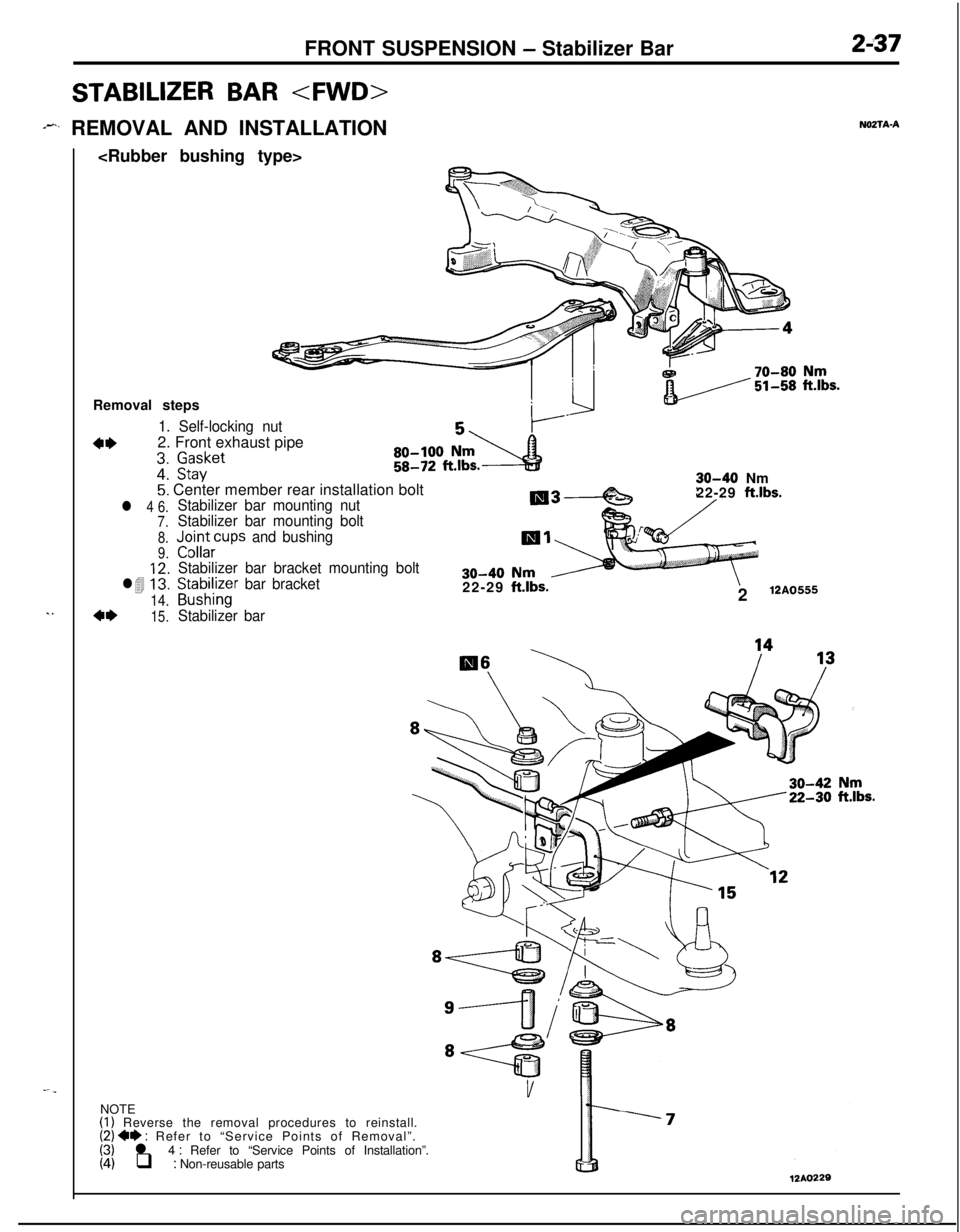
FRONT SUSPENSION - Stabilizer Bar2-37
STABILIZER BAR
-I*_ REMOVAL AND INSTALLATION
. .Removal steps
1. Self-locking nut
4*2. Front exhaust pipez’
gitket5: Center member rear installation bolt
l 4 6.Stabilizer bar mounting nut
7.Stabilizer bar mounting bolt
8.J&~;~cups and bushing
Stabilizer bar bracket mounting bolt
Sg:asAi;r bar bracket
Stabilizer bar
9.
l41::
14.4*15.22-29
ft.lbs.
30-40 Nm
22-29 ft.lbs.2
12A0555
NO2TAANOTE
(I) Reverse the removal procedures to reinstall.(2) 4* : Refer to “Service Points of Removal”.(3) l 4 : Refer to “Service Points of Installation”.(4) q : Non-reusable parts12*0229
Page 86 of 1216
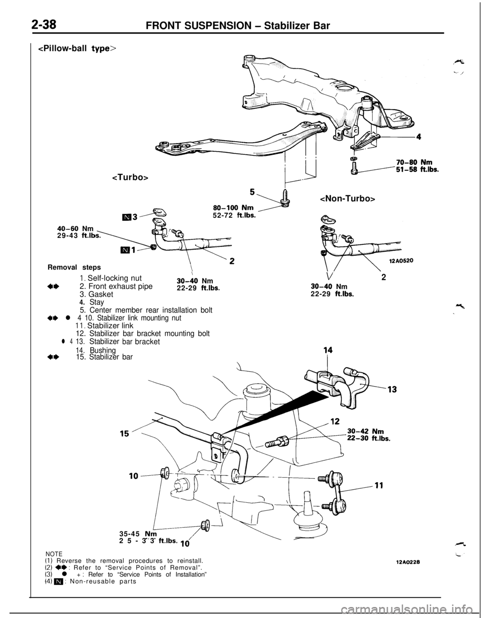
2-38FRONT SUSPENSION - Stabilizer Bar
40-60 Nm
29-43 fLlb52-72
klbs.
Removal steps
4*
1, Self-locking nut
2. Front exhaust pipe
3. Gasket30-:O Nm
22-29 ftlbs.
V2
30-40 Nm
22-29 ft.lbs.
4.Stay
5. Center member rear installation bolt
4e l 4 10. Stabilizer link mounting nutII. Stabilizer link12. Stabilizer bar bracket mounting bolt
l 413.Stabilizerbarbracket
14.Bushing4*15. Stabilizer bar
c- r35-45
25-33
ft.lbs. 10
NOTE(I) Reverse the removal procedures to reinstall.(2) 4e : Refer to “Service Points of Removal”.(3) l + : Refer to “Service Points of Installation”(4) m : Non-reusable parts12A0228