service indicator MITSUBISHI ECLIPSE 1991 User Guide
[x] Cancel search | Manufacturer: MITSUBISHI, Model Year: 1991, Model line: ECLIPSE, Model: MITSUBISHI ECLIPSE 1991Pages: 1216, PDF Size: 67.42 MB
Page 598 of 1216
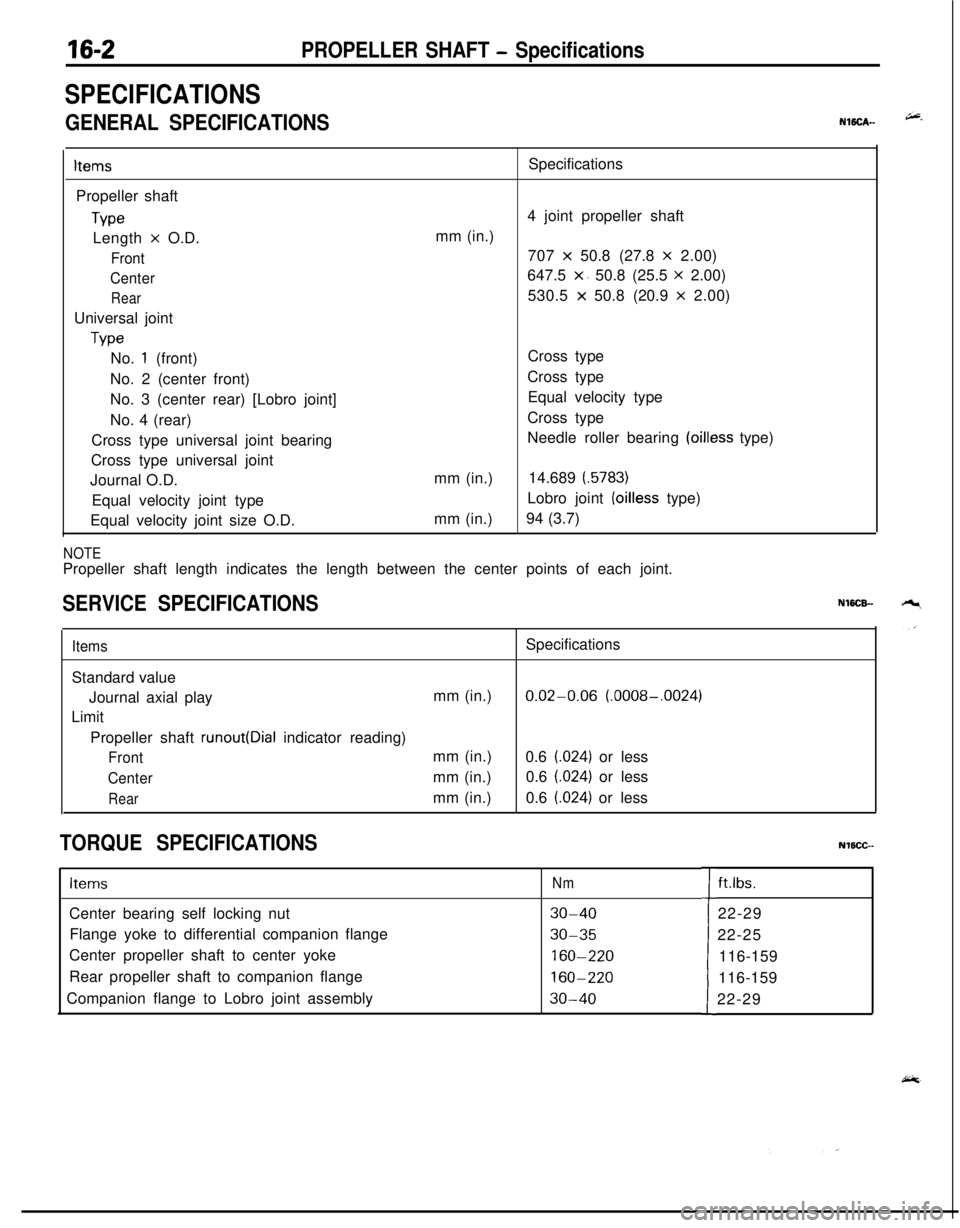
16-2PROPELLER SHAFT - Specifications
SPECIFICATIONS
GENERAL SPECIFICATIONSNWCA--
ItemsPropeller shaft
TypeLength
x O.D.
Front
Center
RearUniversal joint
TypeSpecifications
4 joint propeller shaft
mm (in.)
707
x 50.8 (27.8 x 2.00)
647.5
x. 50.8 (25.5 x 2.00)
530.5
x 50.8 (20.9 x 2.00)
No.
1 (front)
No. 2 (center front)
No. 3 (center rear) [Lobro joint]
No. 4 (rear)
Cross type universal joint bearing
Cross type universal joint
Journal O.D.
Equal velocity joint type
Equal velocity joint size O.D.mm (in.)
mm (in.)Cross type
Cross type
Equal velocity type
Cross type
Needle roller bearing
(oilless type)
14.689
(.5783)Lobro joint
(oilless type)
94 (3.7)
NOTEPropeller shaft length indicates the length between the center points of each joint.
SERVICE SPECIFICATIONSNWCB-
ItemsSpecifications
Standard value
Journal axial playmm (in.)
0.02-0.06 (.0008-.0024)
Limit
Propeller shaft
runout(Dial indicator reading)
Frontmm (in.)
0.6 (.024) or less
Centermm (in.)0.6 (.024) or less
Rearmm (in.)0.6 (.024) or less
TORQUE SPECIFICATIONSNlBCC--
ItemsNmCenter bearing self locking nut
30-40Flange yoke to differential companion flange
30-35Center propeller shaft to center yoke
160-220Rear propeller shaft to companion flange
160-220Companion flange to Lobro joint assembly
30-40tft.lbs.
22-29
22-25
116-159
116-159
22-29
Page 601 of 1216
PROPELLER SHAFT - Propeller Shaft
2.Do not lower rear end of the vehicle as the oil will flow
out of the transfer.
3.Be cautious to avoid damage to the oil seal lip of the
transfer.
4. ,.Use the special tool provided as a cover to prevent the
entry of foreign objects into the transfer.
lOW504lOW5OC
lOGO
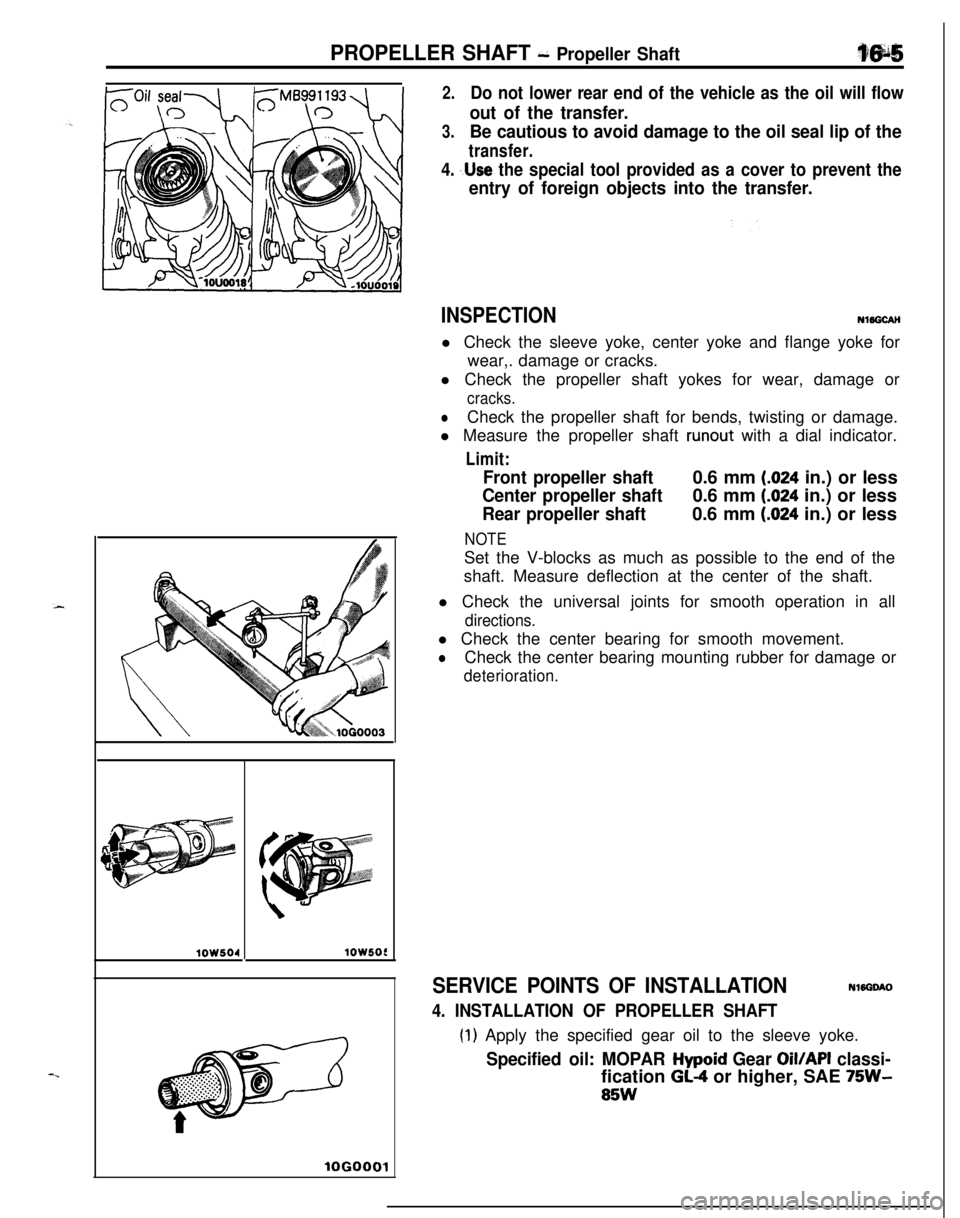
INSPECTIONNl5GCAH
l Check the sleeve yoke, center yoke and flange yoke for
wear,. damage or cracks.
l Check the propeller shaft yokes for wear, damage or
cracks.
lCheck the propeller shaft for bends, twisting or damage.
l Measure the propeller shaft
runout with a dial indicator.
Limit:
Front propeller shaft0.6 mm (.024 in.) or less
Center propeller shaft0.6 mm (.024 in.) or less
Rear propeller shaft0.6 mm (.024 in.) or less
NOTESet the V-blocks as much as possible to the end of the
shaft. Measure deflection at the center of the shaft.
l Check the universal joints for smooth operation in all
directions.l Check the center bearing for smooth movement.
lCheck the center bearing mounting rubber for damage or
deterioration.
SERVICE POINTS OF INSTALLATIONNWGOAO
4. INSTALLATION OF PROPELLER SHAFT
(1) Apply the specified gear oil to the sleeve yoke.
Specified oil: MOPAR Hypoid Gear Oil/API classi-fication
GL-4 or higher, SAE 75W-
85W
Page 904 of 1216
21-210AUTOMATIC TRANSAXLE - Service Adjustment Procedures
OSA0141
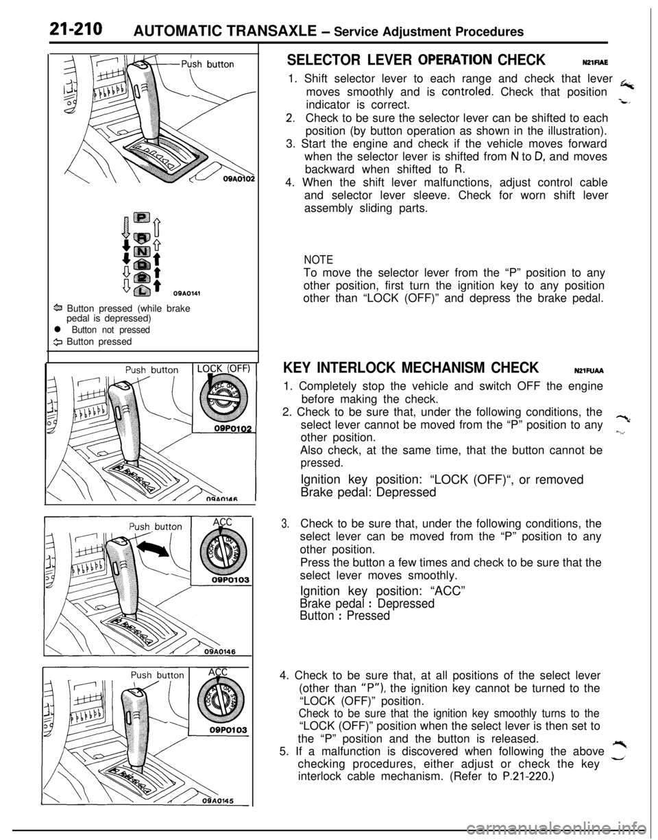
ti Button pressed (while brake
pedal is depressed)
l Button not pressed
9 Button pressed
SELECTOR LEVER OPERATlON CHECKNZlFlAE1. Shift selector lever to each range and check that lever
+moves smoothly and is controled. Check that position
indicator is correct.
-L*
2.Check to be sure the selector lever can be shifted to each
position (by button operation as shown in the illustration).
3. Start the engine and check if the vehicle moves forward
when the selector lever is shifted from
N to D, and moves
backward when shifted to
R.4. When the shift lever malfunctions, adjust control cable
and selector lever sleeve. Check for worn shift lever
assembly sliding parts.
NOTETo move the selector lever from the “P” position to any
other position, first turn the ignition key to any position
other than “LOCK (OFF)” and depress the brake pedal.
KEY INTERLOCK MECHANISM CHECKNZlFUAA1. Completely stop the vehicle and switch OFF the engine
before making the check.
2. Check to be sure that, under the following conditions, the
select lever cannot be moved from the “P” position to any
?cother position.
~.‘,Also check, at the same time, that the button cannot be
pressed.Ignition key position:
“LOCK (OFF)“, or removed
Brake pedal: Depressed
3.Check to be sure that, under the following conditions, the
select lever can be moved from the “P” position to any
other position.
Press the button a few times and check to be sure that the
select lever moves smoothly.
Ignition key position: “ACC”
Brake pedal : Depressed
Button
: Pressed4. Check to be sure that, at all positions of the select lever
(other than
“P”), the ignition key cannot be turned to the
“LOCK (OFF)” position.
Check to be sure that the ignition key smoothly turns to the“LOCK (OFF)” position when the select lever is then set to
the “P” position and the button is released.
5. If a malfunction is discovered when following the above
,”checking procedures, either adjust or check the key
interlock cable mechanism. (Refer to
P.21-220.)
Page 915 of 1216
AUTOMATIC TRANSAXLE - Transaxle Control
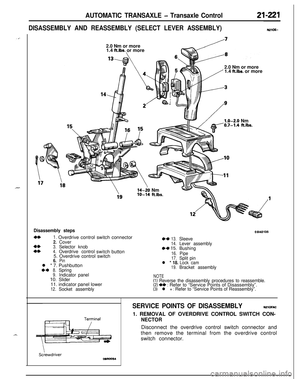
DISASSEMBLY AND REASSEMBLY (SELECT LEVER ASSEMBLY)N210E--2.0 Nm or more
1.4
ft.lbs. or more
2.0 Nm or more
1.4
ft.lbs. or more
/1.0-2.0 Nm0.7-1.4 ft.lbs.14-20 Nm
lo-14 ft.lbs.
Disassembly steps
4+1. Overdrive control switch connector2.Cover3.Selector knob::4.Overdrive controlswitchbutton
5. Overdrive control switch
6.Pinl * 7. Pushbutton
ea8.Spring9.Indicator panel10.Slider11. indicator panel lower
12.Socket assembly
OSA0135
*413.Sleeve14.Lever assemblyI)+15.Bushing
16.Pipe17.Split pinl * 18. Lock cam19.Bracket assembly
NOTE(I) Reverse the disassembly procedures to reassemble.(2) ++ : Refer to “Service Points of Disassembly”.(3) l + : Refer to “Service Points of Reassembly”.
Sciewdriver
SERVICE POINTS OF DISASSEMBLYN21OFAC1. REMOVAL OF OVERDRIVE CONTROL SWITCH CON-
NECTORDisconnect the overdrive control switch connector and
then remove the terminal from the overdrive control
switch connector.
Page 1042 of 1216
22-4WHEELS AND TIRES - Service Adjustment Procedures
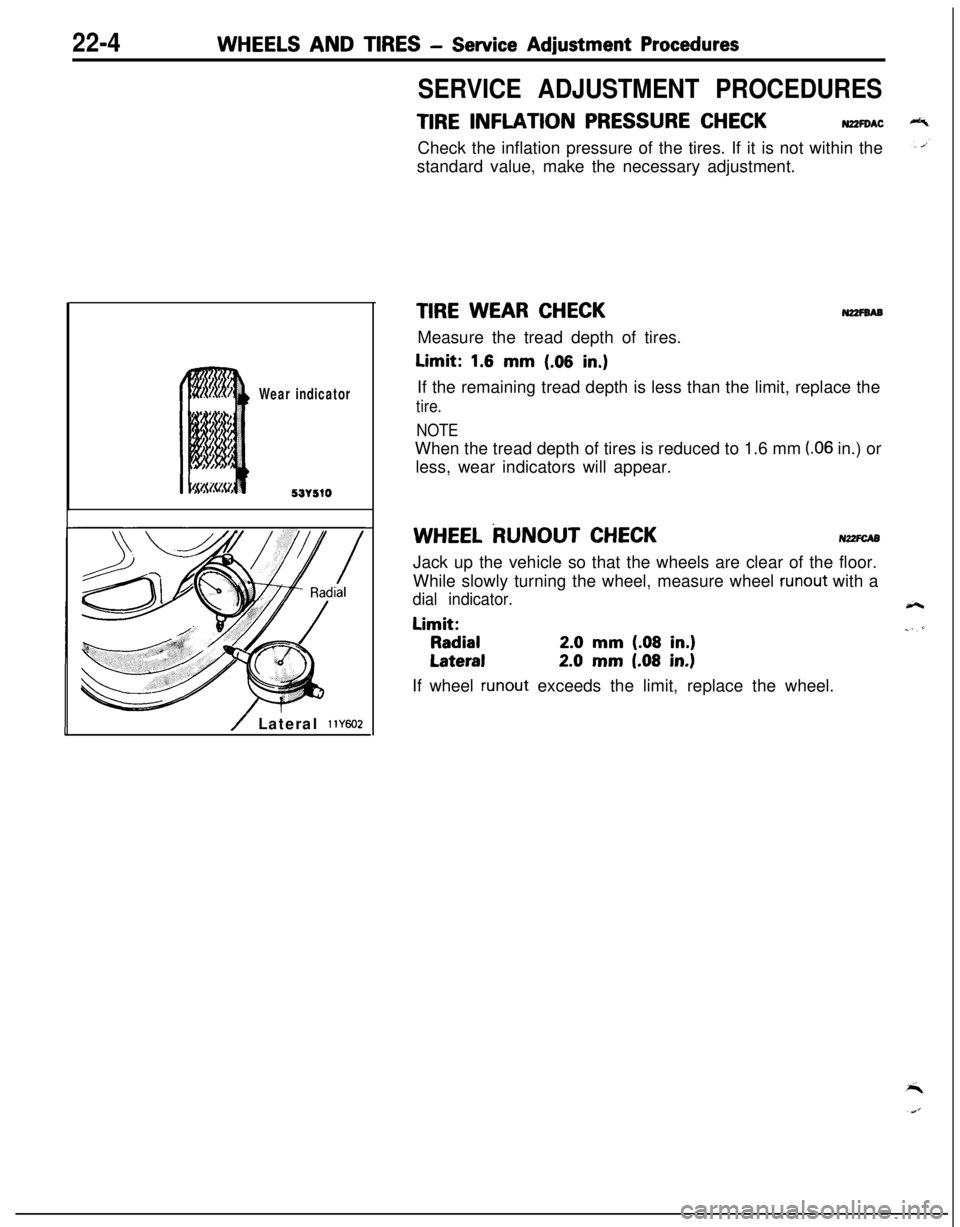
Wear indicator
53r510
/ Lateral 11Y602
SERVICE ADJUSTMENT PROCEDURES
TIRE INFLATION PRESSURE CHECKN2ZFOACCheck the inflation pressure of the tires. If it is not within the
standard value, make the necessary adjustment.
TIRE WEAR CHECKN2zFsABMeasure the tread depth of tires.Limit:
1.6 mm (.06 in,)If the remaining tread depth is less than the limit, replace the
tire.
NOTEWhen the tread depth of tires is reduced to 1.6 mm
(.06 in.) or
less, wear indicators will appear.
WHEEL RUNOUT CHECKNZ2FCA5Jack up the vehicle so that the wheels are clear of the floor.
While slowly turning the wheel, measure wheel
runout with a
dial indicator.Limit:
Radial2.0 mm (.08 in.)
Lateral2.0 mm (.08 in.)If wheel
runout exceeds the limit, replace the wheel.
Page 1155 of 1216
HEATERS AND AIR CONDITIONING - Service Adjustment Procedures 24-I 1
SERVICE ADJUSTMENT PROCEDURES
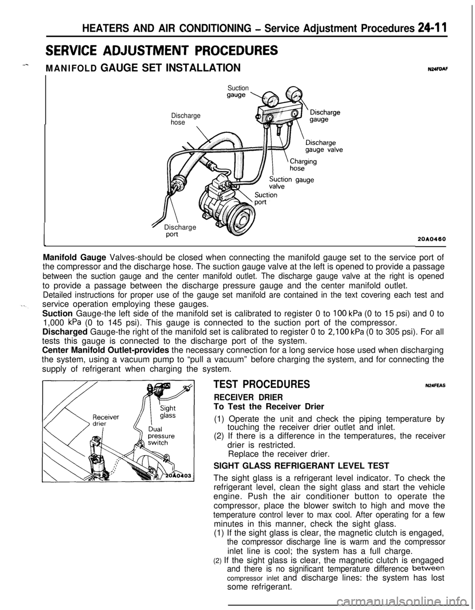
MANIFOLD GAUGE SET INSTALLATION
Suction
gauge
N24FDAF
Discharge
hose
7 Discharge
Port20A0460Manifold Gauge Valves-should be closed when connecting the manifold gauge set to the service port of
the compressor and the discharge hose. The suction gauge valve at the left is opened to provide a passage
between the suction gauge and the center manifold outlet. The discharge gauge valve at the right is openedto provide a passage between the discharge pressure gauge and the center manifold outlet.
Detailed instructions for proper use of the gauge set manifold are contained in the text covering each test andservice operation employing these gauges.
Suction Gauge-the left side of the manifold set is calibrated to register 0 to
100 kPa (0 to 15 psi) and 0 to
1,000
kPa (0 to 145 psi). This gauge is connected to the suction port of the compressor.
Discharged Gauge-the right of the manifold set is calibrated to register 0 to
2,100 kPa (0 to 305 psi). For all
tests this gauge is connected to the discharge port of the system.
Center Manifold Outlet-provides the necessary connection for a long service hose used when discharging
the system, using a vacuum pump to “pull a vacuum”before charging the system, and for connecting the
supply of refrigerant when charging the system.
TEST PROCEDURESN24FEAS
RECEIVER DRIERTo Test the Receiver Drier
(1) Operate the unit and check the piping temperature by
touching the receiver drier outlet and inlet.
(2) If there is a difference in the temperatures, the receiver
drier is restricted.
Replace the receiver drier.
SIGHT GLASS REFRIGERANT LEVEL TEST
The sight glass is a refrigerant level indicator. To check the
refrigerant level, clean the sight glass and start the vehicle
engine. Push the air conditioner button to operate the
compressor, place the blower switch to high and move the
temperature control lever to max cool. After operating for a fewminutes in this manner, check the sight glass.
(1) If the sight glass is clear, the magnetic clutch is engaged,
the compressor discharge line is warm and the compressorinlet line is cool; the system has a full charge.
(2) If the sight glass is clear, the magnetic clutch is engaged
and there is no significant temperature difference between
compressor inlet and discharge lines: the system has lost
some refrigerant.
Page 1216 of 1216
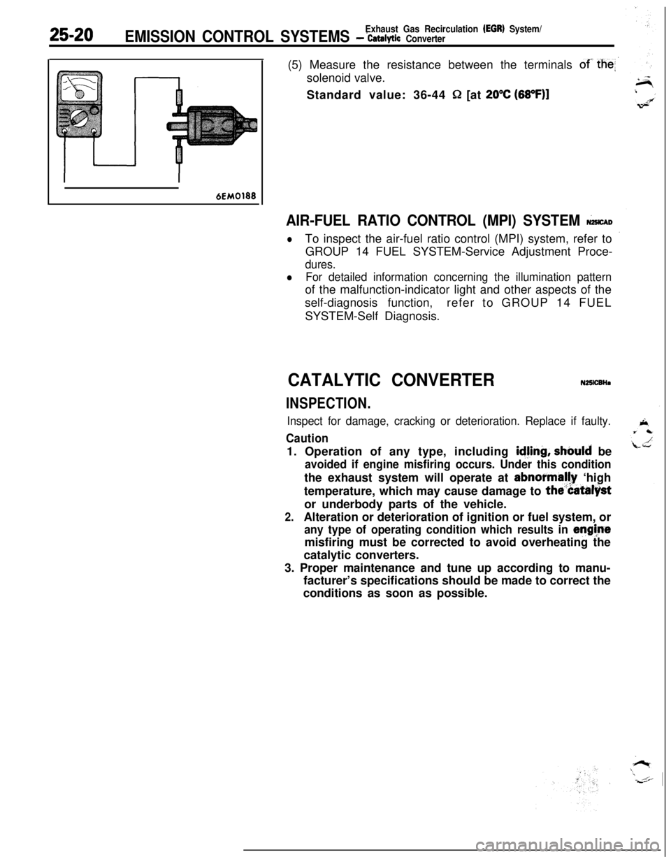
25-20Exhaust Gas Recirculation (EGR) System/EMISSION CONTROL SYSTEMS - ‘catalytic Converter(5) Measure the resistance between the terminals
of- the
Q [at 20°C (68OF)l
6EM0188
AIR-FUEL RATIO CONTROL (MPI) SYSTEM &CAD
lTo inspect the air-fuel ratio control (MPI) system, refer to
GROUP 14 FUEL SYSTEM-Service Adjustment Proce-
dures.
lFor detailed information concerning the illumination patternof the malfunction-indicator light and other aspects of the
self-diagnosis function,refer to GROUP 14 FUEL
SYSTEM-Self Diagnosis.
CATALYTIC CONVERTERN25lCBHa
INSPECTION.
Inspect for damage, cracking or deterioration. Replace if faulty.
Caution1. Operation of any type, including
idjing, should be
avoided if engine misfiring occurs. Under this conditionthe exhaust system will operate at abnormally ‘high
temperature, which may cause damage to
the”Catalystor underbody parts of the vehicle.
2.Alteration or deterioration of ignition or fuel system, or
any type of operating condition which results in enghtemisfiring must be corrected to avoid overheating the
catalytic converters.
3. Proper maintenance and tune up according to manu-
facturer’s specifications should be made to correct the
conditions as soon as possible.