window MITSUBISHI ECLIPSE 1991 Service Manual
[x] Cancel search | Manufacturer: MITSUBISHI, Model Year: 1991, Model line: ECLIPSE, Model: MITSUBISHI ECLIPSE 1991Pages: 1216, PDF Size: 67.42 MB
Page 1045 of 1216
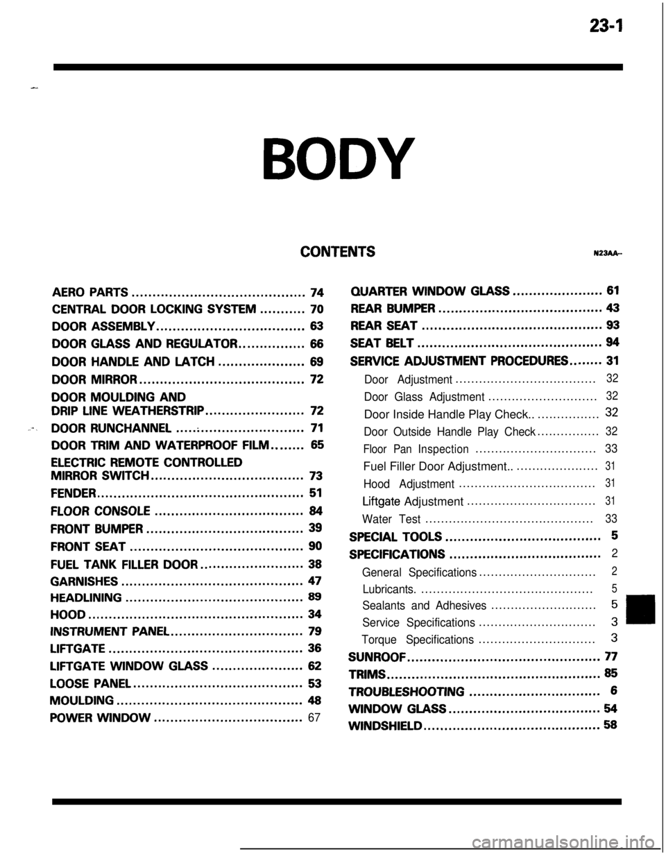
23-lBODY
CONTENTSN23Ak-
AERO PARTS..........................................74
CENTRAL DOOR LOCKING SYSTEM...........70
DOOR ASSEMBLY....................................63
DOOR GLASS AND REGULATOR................66
DOORHANDLEANDLATCH.....................69
DOOR MIRROR........................................72
DOOR MOULDING AND
DRIP LINE WEATHERSTRIP........................72
....DOOR RUNCHANNEL...............................71
DOOR TRIM AND WATERPROOF FILM........65
ELECTRIC REMOTE CONTROLLED
MIRROR SWITCH.....................................73
FENDER..................................................51
FLOOR CONSOLE....................................84
FRONT BUMPER......................................39
FRONT SEAT..........................................90
FUEL TANKFILLERDOOR.........................38
GARNISHES............................................47
HEADLINING...........................................89
HOOD....................................................34
INSTRUMENT PANEL................................79
LIFTGATE...............................................36
LIFTGATE WINDOWGLASS......................62
LOOSE PANEL.........................................53
MOULDING.............................................48
POWER WINDOW....................................67
QUARTERWINDOWGLASS......................61
REAR BUMPER........................................43
REAR SEAT............................................93
SEAT BELT.............................................94
SERVICE ADJUSTMENT PROCEDURES........31
Door Adjustment....................................32
Door Glass Adjustment............................32Door Inside Handle Play Check..................
32
Door Outside Handle Play Check................32
Floor PanInspection...............................
33Fuel Filler Door Adjustment.......................
31
Hood Adjustment...................................31
Liftgate Adjustment.................................31
Water Test...........................................33
SPECIAL TOOLS......................................5
SPECIFICATIONS.....................................2
General Specifications..............................
2
Lubricants.............................................5
Sealants and Adhesives...........................5
Service Specifications..............................3
Torque Specifications..............................3
SUNROOF...............................................77TRIMS
....................................................85
TROUBLESHOOTING................................6WINDOW
GLASS.....................................54
WINDSHIELD...........................................58
Page 1046 of 1216
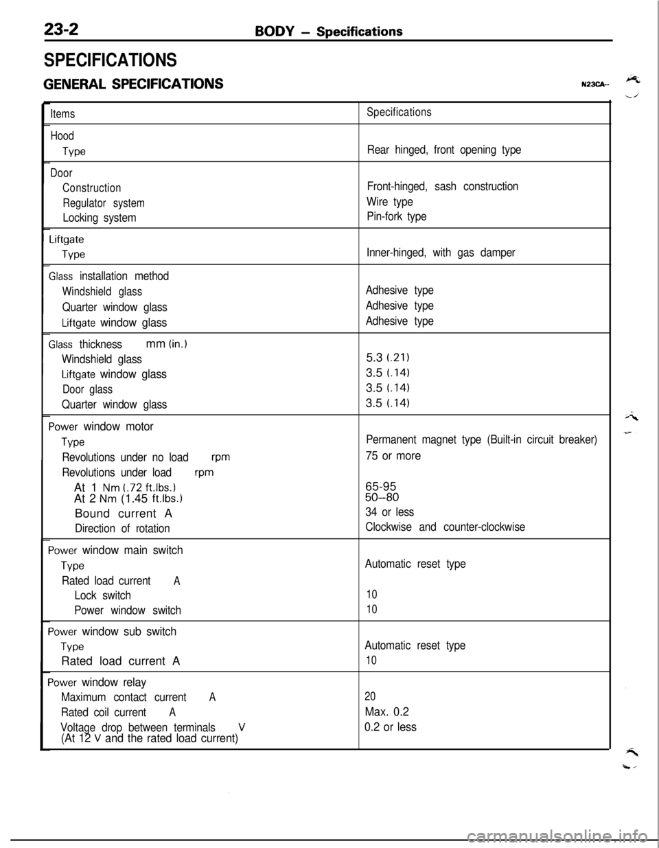
23-2
SPECIFICATIONS
GENERAL SPECIFICATIONS
BODY - Specifications
N23CA--
Items
Hood
We
Door
Construction
Regulator system
Locking system
Liftgate
We
Slass installation method
Windshield glass
Quarter window glass
Liftgate window glass
Zlass thicknessmm (in.)
Windshield glass
Liftgate window glass
Door glass
Quarter window glass
‘ower window motor
Type
Revolutions under no loadwm
Revolutions under load
wmAt 1
Nm t.72 ft.lbs.1At 2
Nm (1.45 ft.lbs.1Bound current A
Direction of rotation
‘ower window main switch
Type
Rated load currentA
Lock switch
Power window switch
‘ower window sub switch
TvwRated load current A
‘ower window relay
Maximum contact currentA
Rated coil currentA
Voltage drop between terminalsV(At 12 V and the rated load current)
Specifications
Rear hinged, front opening type
Front-hinged, sash construction
Wire type
Pin-fork type
Inner-hinged, with gas damper
Adhesive type
Adhesive type
Adhesive type5.3
i.21)3.5
t.1413.5
t.1413.5
t.141
Permanent magnet type (Built-in circuit breaker)
75 or more65-95
50-80
34 or less
Clockwise and counter-clockwise
Automatic reset type
10
10
Automatic reset type
10
20
Max. 0.2
0.2 or less
Page 1048 of 1216
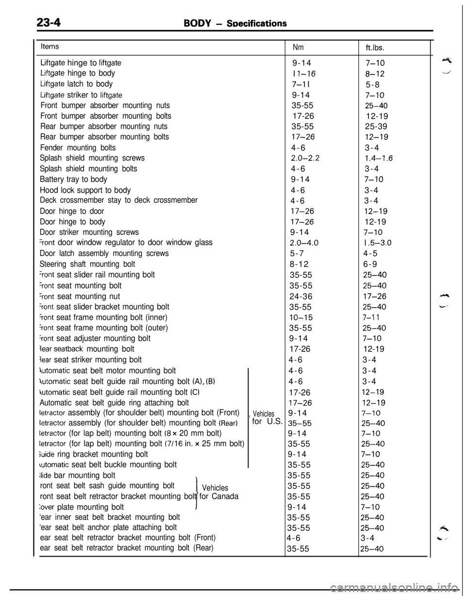
23-4BODY - SDecifications
Items
Nmft.lbs.
Liftgate hinge to liftgate9-147-10
Liftgate hinge to bodyI I-168-12
Liftgate latch to body7-l I
5-8
Liftgate striker to liftgate9-147-10
Front bumper absorber mounting nuts35-5525-40
Front bumper absorber mounting bolts17-26
12-19
Rear bumper absorber mounting nuts35-5525-39
Rear bumper absorber mounting bolts17-2612-19
Fender mounting bolts4-63-4
Splash shield mounting screws2.0-2.21.4-1.6
Splash shield mounting bolts4-63-4
Battery tray to body9-147-10
Hood lock support to body4-63-4
Deck crossmember stay to deck crossmember4-63-4
Door hinge to door17-2612-19
Door hinge to body17-2612-19
Door striker mounting screws9-147-10
%ont door window regulator to door window glass2.0-4.0I .5-3.0
Door latch assembly mounting screws5-74-5
Steering shaft mounting bolt8-126-9
‘rant seat slider rail mounting bolt35-5525-40
Yont seat mounting bolt35-5525-40
‘rant seat mounting nut24-3617-26
‘rant seat slider bracket mounting bolt35-5525-40
‘rant seat frame mounting bolt (inner)10-157-l 1
‘rant seat frame mounting bolt (outer)35-5525-40
‘rant seat adjuster mounting bolt9-147-10
lear seatback mounting bolt17-2612-19
jear seat striker mounting bolt4-63-4
4utomatic seat belt motor mounting bolt4-63-4
jutomatic seat belt guide rail mounting bolt (A), (B)4-63-4
iutomatic seat belt guide rail mounting bolt (Cl17-2612-19
Automatic seat belt guide ring attaching bolt17-2612-19
detractor assembly (for shoulder belt) mounting bolt (Front), Vehicles9-147-10
detractor assembly (for shoulder belt) mounting bolt (Rear)for U.S. 35-5525-40
detractor (for lap belt) mounting bolt (8 x 20 mm bolt)9-147-10
letractor (for lap belt) mounting bolt (7116 in. x 25 mm bolt)35-5525-40
;uide ring bracket mounting bolt9-147-10
automatic seat belt buckle mounting bolt35-5525-40
Jide bar mounting bolt
I35-55
25-40
ront seat belt sash guide mounting boltVehicles35-5525-40
ront seat belt retractor bracket mounting bolt for Canada35-5525-40
Zover plate mounting bolt9-147-10
‘ear inner seat belt bracket mounting bolt35-5525-40
‘ear seat belt anchor plate attaching bolt35-5525-40
ear seat belt retractor bracket mounting bolt (Front)4-63-4
ear seat belt retractor bracket mounting bolt (Rear)35-5525-40
Page 1049 of 1216
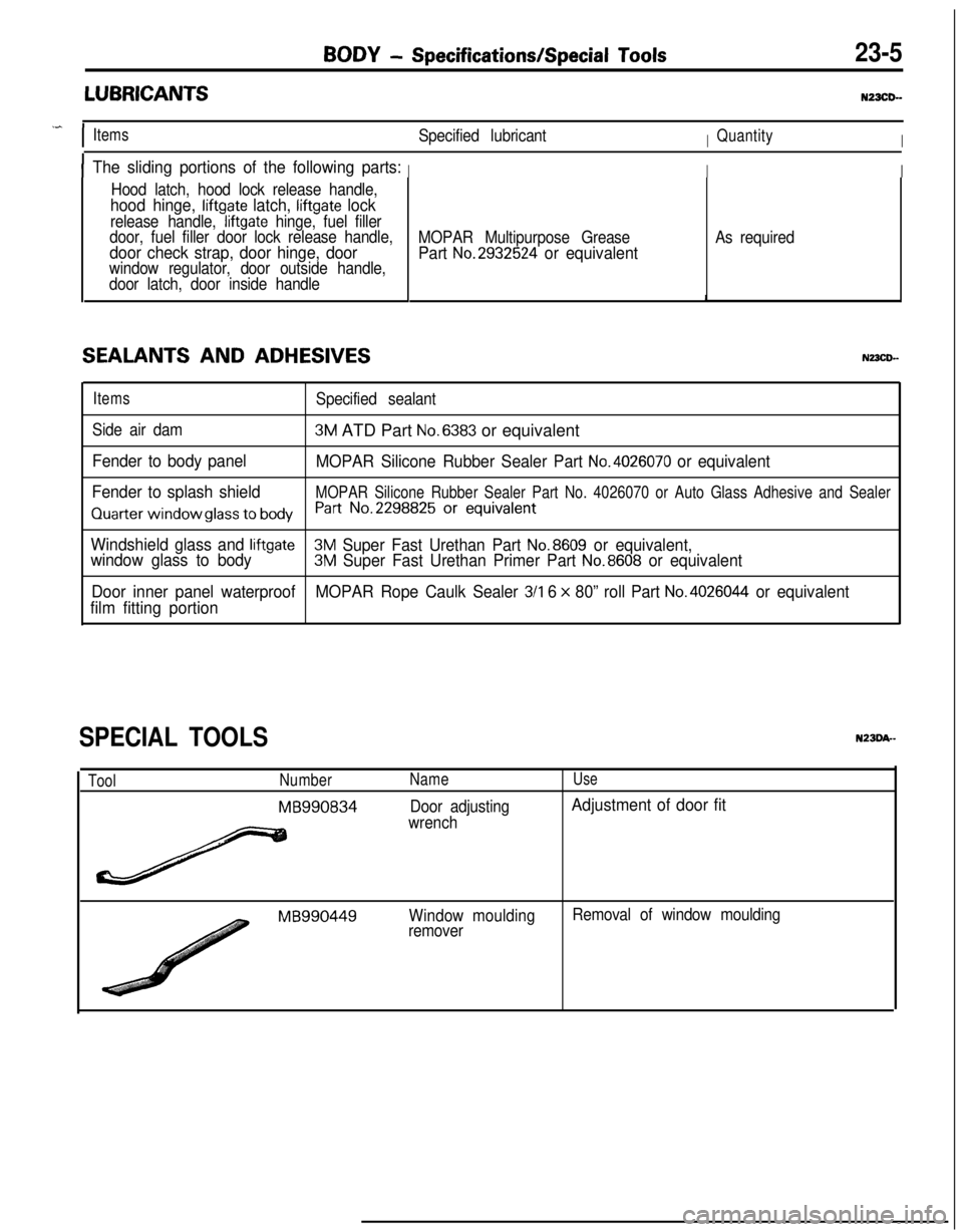
BODY - Specifications/Special Tools23-5
LUBRICANTSNZXD-
.^
IItemsSpecified lubricantIQuantityI
IThe sliding portions of the following parts:III
Hood latch, hood lock release handle,
hood hinge, liftgate latch, liftgate lock
release handle, liftgate hinge, fuel filler
door, fuel filler door lock release handle,
door check strap, door hinge, doorwindow regulator, door outside handle,
door latch, door inside handle
SEALANTS AND ADHESIVES
MOPAR Multipurpose Grease
Part No.2932524 or equivalent
As required
ItemsSpecified sealant
Side air dam
3M ATD Part No.6383 or equivalent
Fender to body panel
MOPAR Silicone Rubber Sealer Part No.4026070 or equivalent
Fender to splash shield
MOPAR Silicone Rubber Sealer Part No. 4026070 or Auto Glass Adhesive and Sealer
Quarter window glass to bodyh-t No.2298825 Or equivalent
Windshield glass and liftgate3M Super Fast Urethan Part No.8609 or equivalent,
window glass to body3M Super Fast Urethan Primer Part No.8608 or equivalent
Door inner panel waterproofMOPAR Rope Caulk Sealer
3/l 6 x 80” roll Part No.4026044 or equivalent
film fitting portion
SPECIAL TOOLS
ToolNumber
MB990834
Name
Door adjusting
wrench
Use
Adjustment of door fit
MB990449Window moulding
removerRemoval of window moulding
Page 1050 of 1216
BODY - Troubleshooting
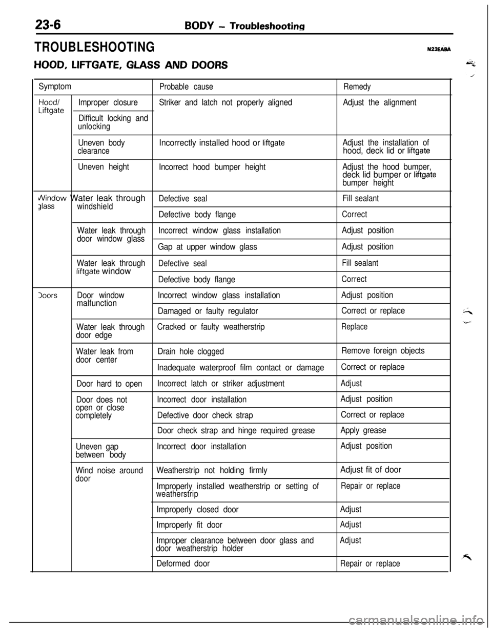
TROUBLESHOOTINGN23EFd
HOOD, LIFTGATE, GLASS AND DOORS
SymptomProbable causeRemedy
Hood/Improper closureStriker and latch not properly alignedAdjust the alignmentLiftgateDifficult locking and
unlocking
Uneven body
clearance
Uneven height
Incorrectly installed hood or liftgate
Incorrect hood bumper heightAdjust the installation of
hood, deck lid or liftgate
Adjust the hood bumper,deck lid bumper or liftgate
bumper height
i/\/indow Water leak throughDefective sealFill sealantJlasswindshield
Defective body flangeCorrect
Water leak throughIncorrect window glass installationAdjust position
door window glass
Gap at upper window glassAdjust position
Water leak through
Defective sealFill sealantliftgate window
Defective body flangeCorrect
IoorsDoor windowIncorrect window glass installationAdjust position
malfunction
Damaged or faulty regulatorCorrect or replace
Water leak throughCracked or faulty weatherstrip
Replace
door edge
Water leak fromDrain hole cloggedRemove foreign objects
door center
Inadequate waterproof film contact or damageCorrect or replace
Door hard to openIncorrect latch or striker adjustment
Adjust
Door does notIncorrect door installationAdjust position
open or close
completelyDefective door check strapCorrect or replace
Door check strap and hinge required greaseApply grease
Uneven gapIncorrect door installationAdjust position
between body
Wind noise aroundWeatherstrip not holding firmly
Adjust fit of door
doorImproperly installed weatherstrip or setting ofRepair or replace
weatherstrip
Improperly closed door
Improperly fit door
Improper clearance between door glass and
door weatherstrip holder
Deformed doorAdjust
Adjust
Adjust
Repair or replace
Page 1053 of 1216
BODY - Troubleshooting23-9
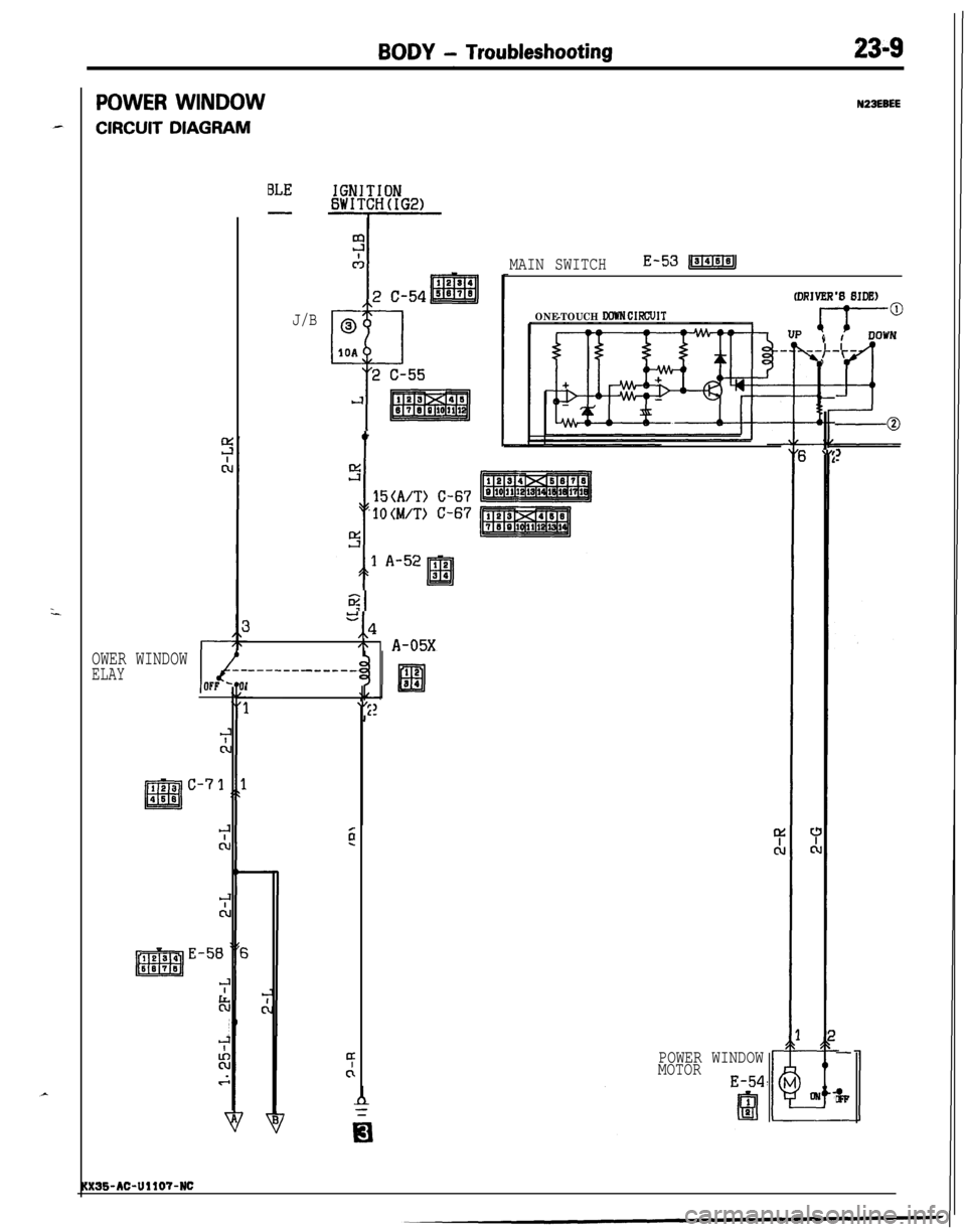
POWER WINDOW
CIRCUIT DIAGRAM
N23EBEE
MAIN SWITCHE-53JIGl=MJ
ONE-TOUCH WWN CIFXXJITJ/B
I
8
c
\,:
-0
t
!Ti
i
15(A/T) C-67
'1OWT) C-67
5
e,,*
'\ A-05X
-------___-_
1
\I2
OWER WINDOWELAY
128 C-7
El468
-
&
POWER WINDOW
MOTOR
E-54
:3S-AC-UllO?-NC
Page 1054 of 1216
23-10BODY - Troubleshooting
(PABBENGER’B BIDE)v 1
E-51
‘S
E-05
I2
m3458
POWER WINDOW
MOTOR
E-04
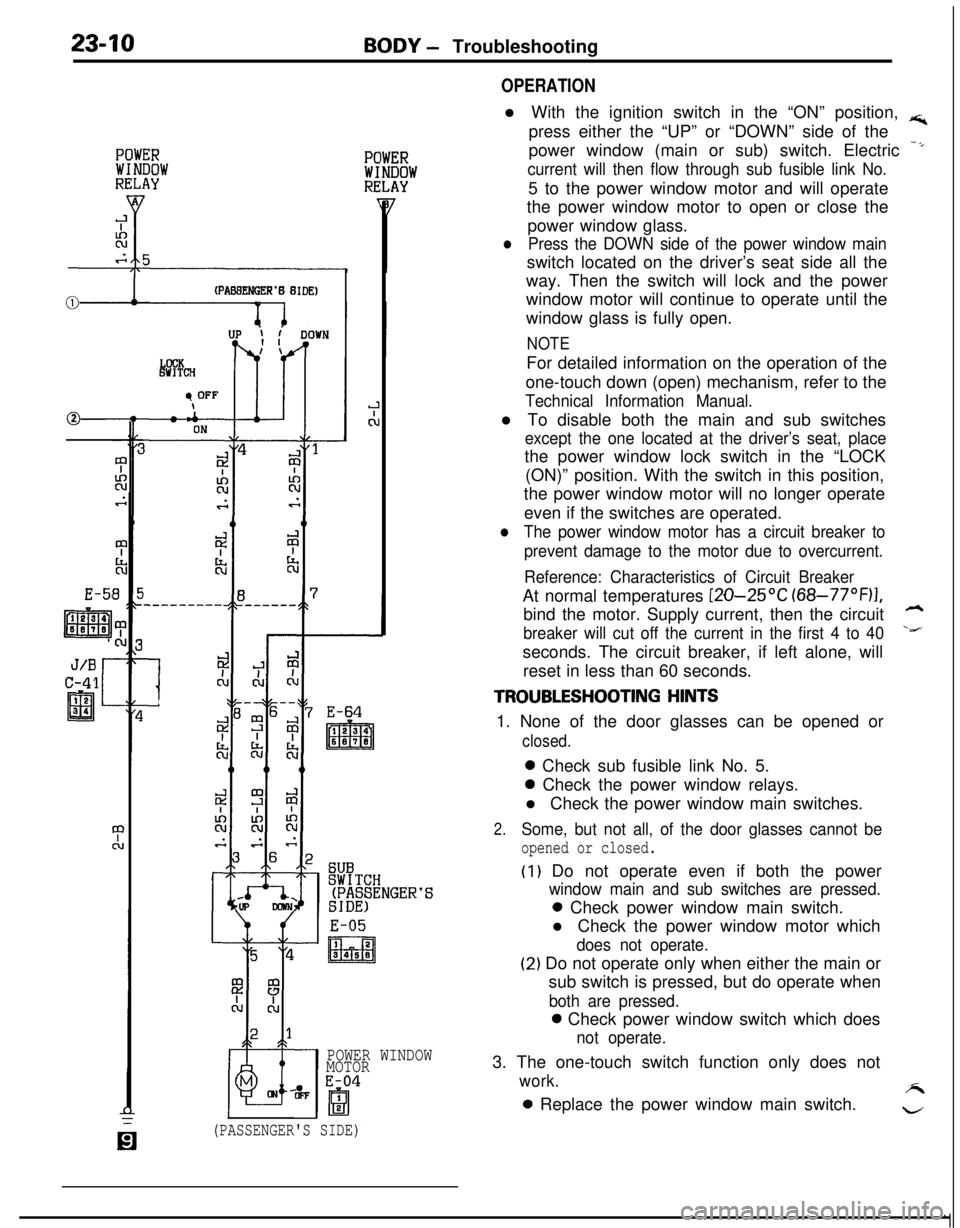
OPERATIONl With the ignition switch in the “ON” position,
rs;,press either the “UP” or “DOWN” side of the
power window (main or sub) switch. Electric
-*
current will then flow through sub fusible link No.5 to the power window motor and will operate
the power window motor to open or close the
power window glass.
lPress the DOWN side of the power window mainswitch located on the driver’s seat side all the
way. Then the switch will lock and the power
window motor will continue to operate until the
window glass is fully open.
NOTEFor detailed information on the operation of the
one-touch down (open) mechanism, refer to the
Technical Information Manual.l To disable both the main and sub switches
except the one located at the driver’s seat, placethe power window lock switch in the “LOCK
(ON)” position. With the switch in this position,
the power window motor will no longer operate
even if the switches are operated.
lThe power window motor has a circuit breaker to
prevent damage to the motor due to overcurrent.
Reference: Characteristics of Circuit BreakerAt normal temperatures
[ZO-25OC (68-77”F)I,bind the motor. Supply current, then the circuit
h
breaker will cut off the current in the first 4 to 40\&’seconds. The circuit breaker, if left alone, will
reset in less than 60 seconds.
TROUBLESHOOTING HINTS1. None of the door glasses can be opened or
closed.0 Check sub fusible link No. 5.0 Check the power window relays.
l Check the power window main switches.
2.Some, but not all, of the door glasses cannot be
opened or closed.
(I) Do not operate even if both the power
window main and sub switches are pressed.0 Check power window main switch.
l Check the power window motor which
does not operate.
(2) Do not operate only when either the main or
sub switch is pressed, but do operate when
both are pressed.0 Check power window switch which does
not operate.3. The one-touch switch function only does not
work.A0 Replace the power window main switch.
w
(PASSENGER'S SIDE)
Page 1076 of 1216
23-32BODY - Service Adjustment Procedures
‘C16A0711
18AO38t
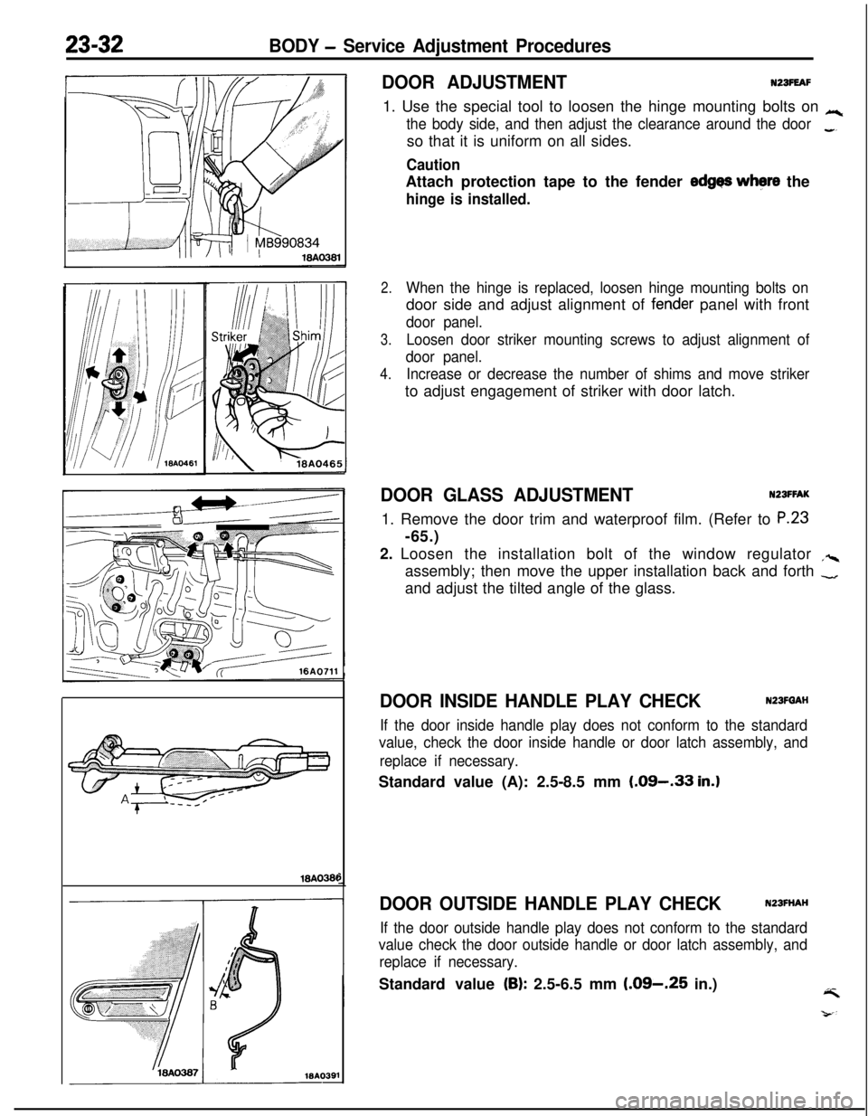
DOOR ADJUSTMENTNZBFEAF1. Use the special tool to loosen the hinge mounting bolts on
Lc
the body side, and then adjust the clearance around the door_so that it is uniform on all sides.
CautionAttach protection tape to the fender
edges where the
hinge is installed.
2.When the hinge is replaced, loosen hinge mounting bolts ondoor side and adjust alignment of
fen,der panel with front
door panel.
3.Loosen door striker mounting screws to adjust alignment of
door panel.
4.Increase or decrease the number of shims and move strikerto adjust engagement of striker with door latch.
DOOR GLASS ADJUSTMENTNZSFFAK1. Remove the door trim and waterproof film. (Refer to
P.23-65.)
2. Loosen the installation bolt of the window regulator
,%assembly; then move the upper installation back and forth
-and adjust the tilted angle of the glass.
DOOR INSIDE HANDLE PLAY CHECKN23FQAH
If the door inside handle play does not conform to the standard
value, check the door inside handle or door latch assembly, and
replace if necessary.Standard value (A): 2.5-8.5 mm
(.09-.33 in.)
DOOR OUTSIDE HANDLE PLAY CHECKN23FHAH
If the door outside handle play does not conform to the standard
value check the door outside handle or door latch assembly, and
replace if necessary.Standard value
(B): 2.5-6.5 mm (.09-.25 in.)4
Page 1092 of 1216
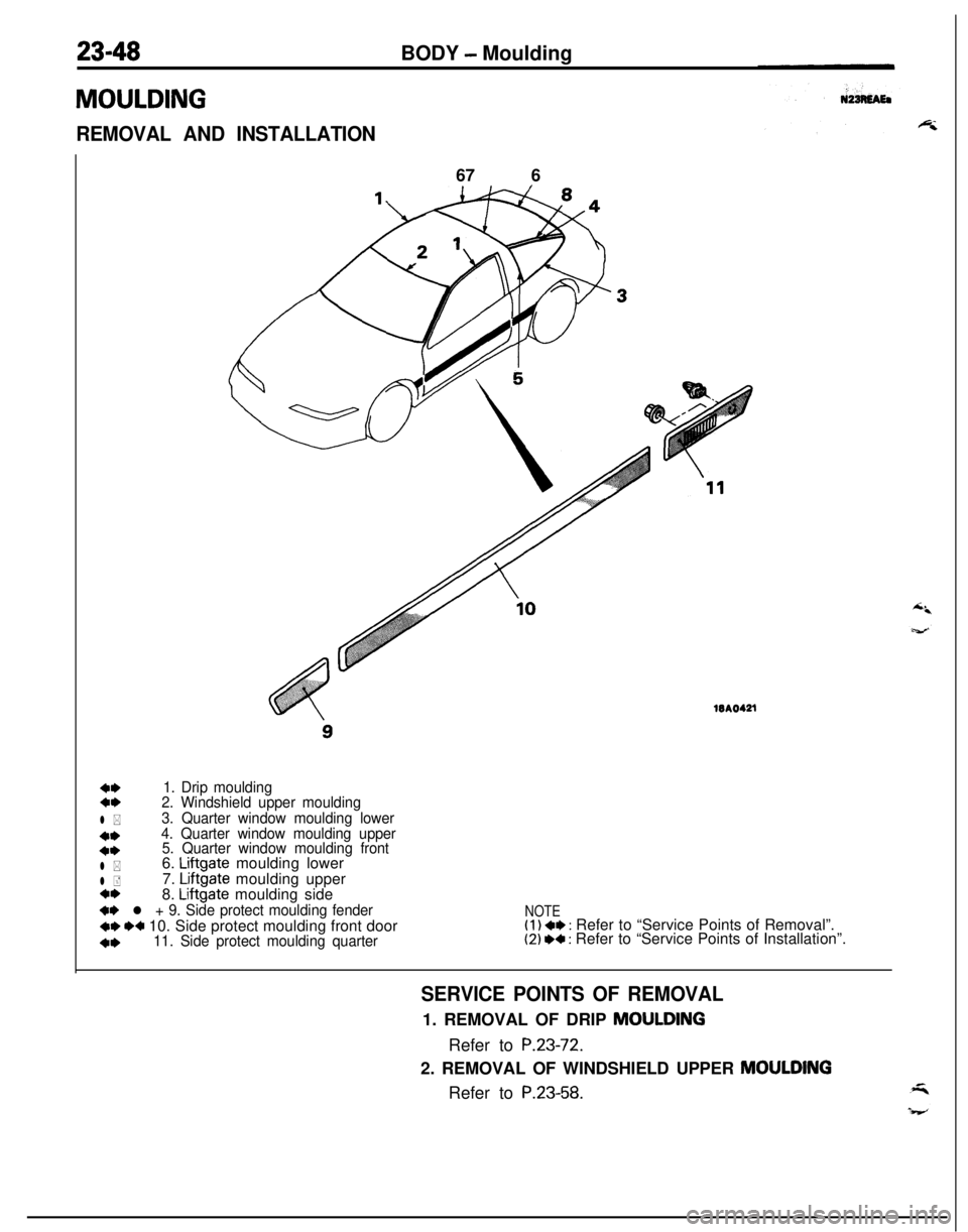
23-48
MOULDINGBODY
- Moulding
REMOVAL AND INSTALLATION67 6WA0421
4,1. Drip moulding4,2. Windshield upper moulding
l *3. Quarter window moulding lower
**4. Quarter window moulding upper
4*5. Quarter window moulding front
l *6. Liftgate moulding lower
l +7. Liftgate moulding uppera*8. Liftgate moulding side
+* l + 9. Side protect moulding fender
+e I)+ 10. Side protect moulding front door
4,11. Side protect moulding quarter
NOTE(1) ** : Refer to “Service Points of Removal”.(2) I)+ : Refer to “Service Points of Installation”.
SERVICE POINTS OF REMOVAL1. REMOVAL OF DRIP MOULDING
Refer to
P.23-72.2. REMOVAL OF WINDSHIELD UPPER
MOULDINGRefer to
P.23-58.
Page 1093 of 1216
BODY - Moulding23-493.
REMOVAL OF QUARTER WINDOW MOULDING LOWER/
4. QUARTER WINDOW MOULDING UPPER/B. QUARTERWINDOW MOULDING FRONT
Refer to
P.23-61.6. REMOVAL OF
LIFTGATE MOULDING LOWERI7. LIFT-GATE MOULDING
UPPER/8. LIFTGATE MOULDING
SIDERefer to
P.23-62.
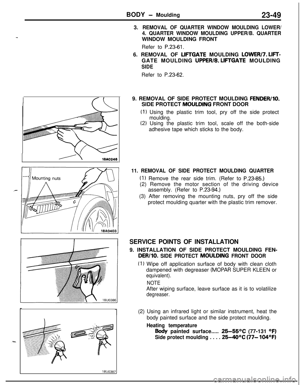
19. REMOVAL OF SIDE PROTECT MOULDING
FENDER/IO.SIDE PROTECT MOULDING FRONT DOOR
(1) Using the plastic trim tool, pry off the side protect
moulding.
(2) Using the plastic trim tool, scale off the both-side
adhesive tape which sticks to the body.
11. REMOVAL OF SIDE PROTECT MOULDING QUARTER
(1) Remove the rear side trim. (Refer to P.23-85.)(2) Remove the motor section of the driving device
assembly. (Refer to
P.23-94.)(3) After removing the mounting nuts, pry off the side
protect moulding quarter with the plastic trim remover.
SERVICE POINTS OF INSTALLATION9. INSTALLATION OF SIDE PROTECT MOULDING FEN-
DER/10. SIDE PROTECT MOULDING FRONT DOOR
(1) Wipe off application surface of body with clean cloth
dampened with degreaser
(MOPAR SUPER KLEEN or
equivalent).
NOTEAfter wiping surface, leave surface as it is to volatilize
degreaser.(2) Using an infrared light or similar instrument, heat the
body painted surface and the side protect moulding.
Heating temperature
Body painted surface..... 25-55OC (77-131 OF)
Side protect moulding . . . . 25-40°C (77- 104OF)