height MITSUBISHI ECLIPSE 1991 Owner's Manual
[x] Cancel search | Manufacturer: MITSUBISHI, Model Year: 1991, Model line: ECLIPSE, Model: MITSUBISHI ECLIPSE 1991Pages: 1216, PDF Size: 67.42 MB
Page 299 of 1216
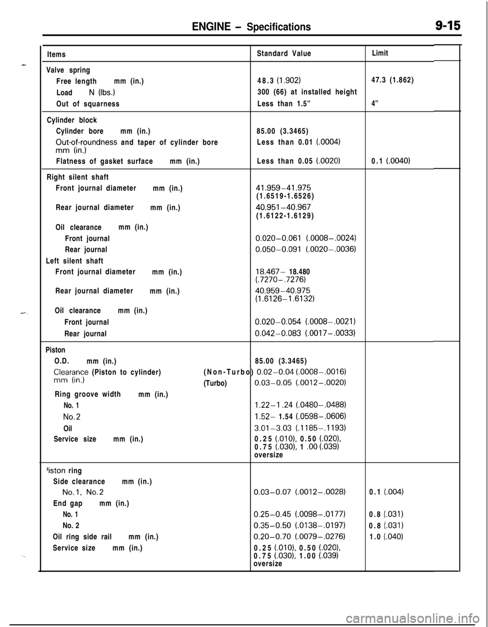
ENGINE - Specifications9-15ItemsStandard ValueLimit
Valve spring
Free lengthmm (in.)48.3
(1.902)47.3 (1.862)
Load
N (Ibs.)300 (66) at installed height
Out of squarnessLess than 1.5”4”
Cylinder block
Cylinder boremm (in.)85.00 (3.3465)
FIu-o$xrndness and taper of cylinder boreLess than 0.01 (0004)Flatness of gasket surfacemm (in.)Less than 0.05
(.0020)0.1 (.0040)Right silent shaft
Front journal diameter
mm (in.)
41.959-41.975(1.6519-1.6526)
Rear journal diameter
mm (in.)
40.951-40.967(1.6122-1.6129)
Oil clearancemm (in.)
Front journal
0.020-0.061 (.0008-.0024)Rear journal
0.050-0.091 (.0020-.0036)Left silent shaft
Front journal diameter
mm (in.)
18.467- 18.480(.7270-.7276)Rear journal diameter
mm (in.)
40.959-40.975
(1.6126-1.6132)Oil clearancemm (in.)
Front journal
0.020-0.054 (.0008-.0021)Rear journal
0.042-0.083 (.0017-.0033)Piston
O.D.
mm (in.)85.00 (3.3465)
CnlIr;;y (Piston to cylinder)(Non-Turbo) 0.02-0.04 (.0008-.0016)(Turbo)
0.03-0.05 (.0012-.0020)Ring groove width
mm (in.)
No. 11.22-l .24 (.0480-.0488)
No.21.52- 1.54 (.0598-.0606)Oil
3.01-3.03 (.1185-.1193)Service sizemm (in.)0.25
(.OlO), 0.50 (.020),0.75
(.030), 1 .oo i.039)oversize‘iston ring
Side clearancemm (in.)
No.1. No.2End gapmm (in.)
No. 1No. 2
Oil ring side railmm (in.)
Service sizemm (in.)
0.03-0.07 (.0012-.0028)
0.25-0.45 (.0098-.0177)
0.35-0.50 (.0138-.0197)
0.20-0.70 (.0079-.0276)0.25
(.OlO), 0.50 (.020),0.75 (030). 1.00 i.039)oversize0.1
(.004)0.8
(.031)0.8
(.031)1.0
(.040)
Page 333 of 1216
ENGINE <1.8L Ennine> -Rocker Arms, Rocker Arm Shafts and Camshaft&49
MD9984431
6EN245
IFuel pump
3EN287
r
0
Camheight6EN0184
hl,
3EN153, Oil seal
MD998364
DEN632
SERVICE POINTS OF DISASSEMBLYNWLFM.
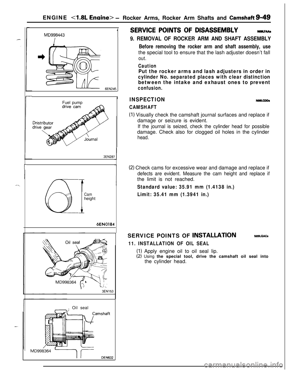
9. REMOVAL OF ROCKER ARM AND SHAFT ASSEMBLYBefore removing the rocker arm and shaft assembly, use
the special tool to ensure that the lash adjuster doesn’t fall
out.
Caution
Put the rocker arms and lash adjusters in order in
cylinder No. separated places with clear distinction
between the intake and exhaust ones to prevent
confusion.
INSPECTION
CAMSHAFT
NOBLCDDI
(1) Visually check the camshaft journal surfaces and replace if
damage or seizure is evident.
If the journal is seized, check the cylinder head for possibledamage. Check also for clogged oil holes in the cylinder
head.
(2) Check cams for excessive wear and damage and replace if
defects are evident. Measure the cam height and replace ifthe limit is not reached.
Standard value: 35.91 mm (1.4138 in.)
Limit: 35.41 mm (1.3941 in.)SERVICE POINTS OF
INSTALLATIONNOSLQACa
11. INSTALLATION OF OIL SEAL
(1) Apply engine oil to oil seal lip.
(2) Using the special tool, drive the camshaft oil seal into
the cylinder head.
Page 339 of 1216
ENGINE - Cylinder Head and Valve9-55
3EN026
w -w===j=Margin , EN034
Squareness
IFree length
INSPECTION
CYLINDER HEADNosocAMl Check the cylinder head for cracks, damage and engine
coolant leakage.l
Remove the scale, sealing compound and carbon deposits
completely. After cleaning oil passages, apply compressedair to make certain that the passages are clear.
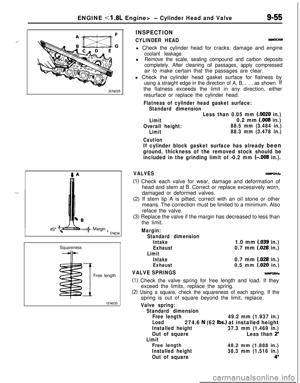
l Check the cylinder head gasket surface for flatness by
using a straight edge in the direction of A, B, . . . as shown. Ifthe flatness exceeds the limit in any direction, either
resurface or replace the cylinder head.
Flatness of cylinder head gasket surface:
Standard dimension
Limit
Overall height:
Limit
Caution
Less than 0.05 mm (0020 in.)
0.2 mm (008 in.)
88.5 mm (3.484 in.)
88.3 mm (3.478 in.)
If cylinder block gasket surface has already been
ground, thickness of the removed stock should be
included in the grinding limit of -0.2 mm
(-,008 in.).
VALVESNo9PGMa
(1) Check each valve for wear, damage and deformation of
head and stem at
B. Correct or replace excessively worn,
damaged or deformed valves.
(2) If stem tip A is pitted, correct with an oil stone or other
means. The correction must be limited to a minimum. Also
reface the valve.
(3) Replace the valve if the margin has decreased to less than
the limit.
Margin:
Standard dimension
Intake1.0 mm (.039 in.)
Exhaust0.7 mm (028 in.)
Limit
Intake0.7 mm (.028 in.)
Exhaust0.5 mm LO20 in.)
VALVE SPRINGSNOWGh
(1) Check the valve spring for free length and load. If they
exceed the limits, replace the spring.
(2) Using a square, check the squareness of each spring. If thespring is out of square beyond the limit, replace.
Valve spring:
Standard dimension
Free length
49.2 mm (1.937 in.)
Load274.6 N (62 Ibs.) at installed height
Installed height37.3 mm (1.469 in.)
Out of square
Less than 2”
Limit
Free length48.2 mm (1.888 in.)
Installed height38.3 mm (1.516 in.)
Out of square4”
Page 357 of 1216
ENGINE <1.8L Engine> - Cylinder Block9-73
lIf cylinder top ridge is worn in stages, smooth out with a
ridge reamer.
l Oversize pistons are available in four sizes.
Piston oversizes and marks:0.25 mm
(.OlO in.) OS. 0.25
0.50 mm
(.020 in.) O.S. 0.50
0.75 mm
(.030 in.) O.S. 0.75
1
.OO mm (.039 in.) O.S. 1.00
lTo rebore the cylinder to an oversize, keep the specified
clearance between the oversize piston and the bore, and
make sure that all pistons used are of the same oversize.
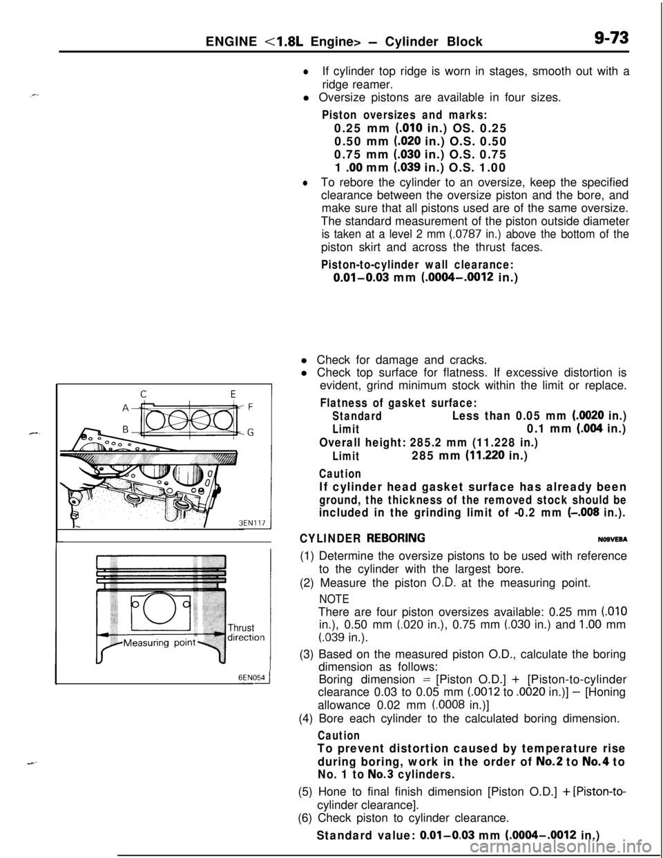
The standard measurement of the piston outside diameter
is taken at a level 2 mm (0787 in.) above the bottom of thepiston skirt and across the thrust faces.
Piston-to-cylinder wall clearance:
0.01-0.03 mm (.0004-.0012 in.)
Thrustdirectiol
6ENOdl Check for damage and cracks.
l Check top surface for flatness. If excessive distortion is
evident, grind minimum stock within the limit or replace.
Flatness of gasket surface:
StandardLess than 0.05 mm (0020 in.)
Limit0.1 mm (.004 in.)
Overall height: 285.2 mm (11.228 in.)
Limit285 mm (11.220 in.)
Caution
If cylinder head gasket surface has already been
ground, the thickness of the removed stock should be
included in the grinding limit of -0.2 mm (-.008 in.).
CYLINDER
REBORINGNOBVEBA(1) Determine the oversize pistons to be used with reference
to the cylinder with the largest bore.
(2) Measure the piston
O.D. at the measuring point.
NOTEThere are four piston oversizes available: 0.25 mm
(.OlOin.), 0.50 mm
(.020 in.), 0.75 mm (.030 in.) and 1.00 mm
(.039 in.).
(3) Based on the measured piston O.D., calculate the boring
dimension as follows:
Boring dimension = [Piston O.D.] + [Piston-to-cylinder
clearance 0.03 to 0.05 mm
(.0012 to .0020 in.)] - [Honing
allowance 0.02 mm
(.0008 in.)]
(4) Bore each cylinder to the calculated boring dimension.
Caution
To prevent distortion caused by temperature rise
during boring, work in the order of
No.2 to No.4 to
No. 1 to No.3 cylinders.(5) Hone to final finish dimension [Piston O.D.]
+ [Piston-to-cylinder clearance].
(6) Check piston to cylinder clearance.
Standard value: 0.01-0.03 mm (.0004-.0012 in.)
Page 394 of 1216
9-110ENGINE <2.0L DOHC Engine> - Camshaft and Rocker Arm
I
I6EN0183
I6EN0184
I
I6EN0185
,I
+Front of engine (Timing belt side)
WIB’ S’it
’ Intake side
camshaft
6E NO289Cap number
Symbolidentifying
intake or
exhaust6EN6464
I
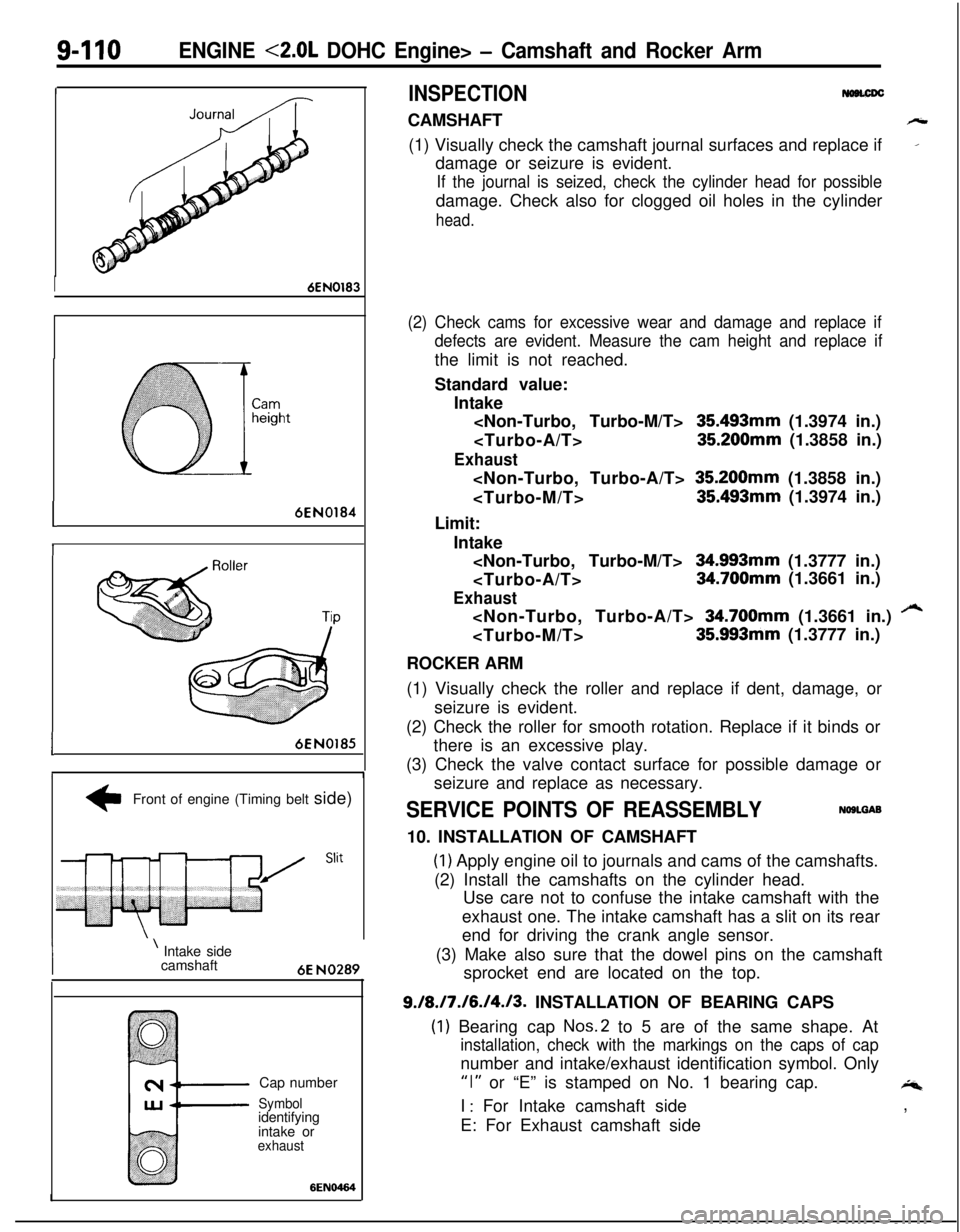
INSPECTIONCAMSHAFT
h(1) Visually check the camshaft journal surfaces and replace if
_damage or seizure is evident.
If the journal is seized, check the cylinder head for possibledamage. Check also for clogged oil holes in the cylinder
head.
(2) Check cams for excessive wear and damage and replace if
defects are evident. Measure the cam height and replace ifthe limit is not reached.
Standard value:
Intake
35493mm (1.3974 in.)
Exhaust
Limit:
Intake
Exhaust
/“4
ROCKER ARM
(1) Visually check the roller and replace if dent, damage, or
seizure is evident.
(2) Check the roller for smooth rotation. Replace if it binds or
there is an excessive play.
(3) Check the valve contact surface for possible damage or
seizure and replace as necessary.
SERVICE POINTS OF REASSEMBLYNOSLGAB10. INSTALLATION OF CAMSHAFT
(1) Apply engine oil to journals and cams of the camshafts.
(2) Install the camshafts on the cylinder head.
Use care not to confuse the intake camshaft with the
exhaust one. The intake camshaft has a slit on its rear
end for driving the crank angle sensor.
(3) Make also sure that the dowel pins on the camshaft
sprocket end are located on the top.
9./8./7./6./4./3. INSTALLATION OF BEARING CAPS
(1) Bearing cap Nos.2 to 5 are of the same shape. At
installation, check with the markings on the caps of capnumber and intake/exhaust identification symbol. Only
“I” or “E” is stamped on No. 1 bearing cap.4I
: For Intake camshaft side
E: For Exhaust camshaft side,
Page 398 of 1216
9-114ENGINE <2.0L DOHC Engine> - Cylinder Head and Valve
Ridgewear
1 EN034Contact with
valve seat
(to be at center
6EN020
I
Freeheight
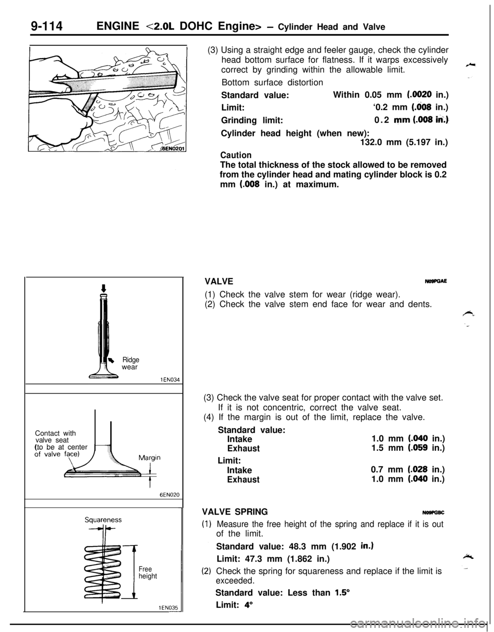
1 EN035-(3) Using a straight edge and feeler gauge, check the cylinder
head bottom surface for flatness. If it warps excessively
correct by grinding within the allowable limit.
Bottom surface distortion
Standard value:Within 0.05 mm
(.0020 in.)
Limit:‘0.2 mm
(.dO8 in.)
Grinding limit:0.2 mm
(.008 iA.)-Cylinder head height (when new):
132.0 mm (5.197 in.)
CautionThe total thickness of the stock allowed to be removed
from the cylinder head and mating cylinder block is 0.2
mm
(.008 in.) at maximum.
VALVE
NOSPGAE(1) Check the valve stem for wear (ridge wear).
(2) Check the valve stem end face for wear and dents.
(3) Check the valve seat for proper contact with the valve set.
If it is not concentric, correct the valve seat.
(4) If the margin is out of the limit, replace the valve.
Standard value:
Intake1.0 mm
(.040 in.)
Exhaust1.5 mm (.059 in.)
Limit:
Intake0.7 mm
1.028 in.)
Exhaust1.0 mm (.040 in.)
VALVE SPRING
NOSPGBC
Measure the free height of the spring and replace if it is outof the limit.
Standard value: 48.3 mm (1.902
in.)Limit: 47.3 mm (1.862 in.)
Check the spring for squareness and replace if the limit is
exceeded.Standard value: Less than
1.5’Limit:
4”
Page 421 of 1216
ENGINE <2.0L DOHC Engine> - Cylinder Block9437
Thrustdirection
6EN054-(3) If the distortion is excessive, correct within the allowable
limit or replace.
Grinding limit: 0.2 mm
(008 in.)
The total thickness of the stock allowed to be
removed from cylinder block and mating cylinder
head is 0.2 mm
(008 in.) at maximum.
Cylinder block height (when new): 284 mm (11.18 in.)
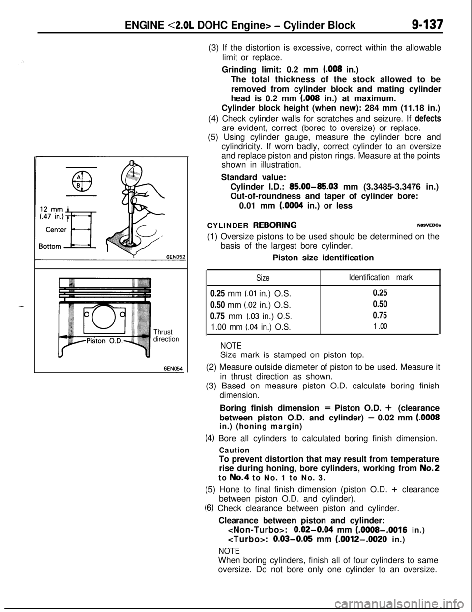
(4) Check cylinder walls for scratches and seizure. If defects
are evident, correct (bored to oversize) or replace.
(5) Using cylinder gauge, measure the cylinder bore and
cylindricity. If worn badly, correct cylinder to an oversize
and replace piston and piston rings. Measure at the points
shown in illustration.
Standard value:
Cylinder I.D.:
85.00-85.03 mm (3.3485-3.3476 in.)
Out-of-roundness and taper of cylinder bore:
0.01 mm
(6064 in.) or less
CYLINDER REBORINGNO9VEDCa(1) Oversize pistons to be used should be determined on the
basis of the largest bore cylinder.
Piston size identification
Size0.25 mm
(.Ol in.) O.S.
0.50 mm
(.02 in.) O.S.
0.75 mm
(.03 in.) OS.
1.00 mm LO4 in.) O.S.
Identification mark0.25
0.50
0.75
1 .oo
NOTESize mark is stamped on piston top.
(2) Measure outside diameter of piston to be used. Measure it
in thrust direction as shown.
(3) Based on measure piston O.D. calculate boring finish
dimension.Boring finish dimension
= Piston O.D. + (clearance
between piston O.D. and cylinder)
- 0.02 mm (.OOOSin.) (honing margin)
(4) Bore all cylinders to calculated boring finish dimension.
CautionTo prevent distortion that may result from temperature
rise during honing, bore cylinders, working from
No.2to No.4 to No. 1 to No. 3.
(5) Hone to final finish dimension (piston O.D. + clearance
between piston O.D. and cylinder).
(6) Check clearance between piston and cylinder.
Clearance between piston and cylinder:
0.02-064 mm (AMOS-,001~ in.)
0.03-0.05 mm (.OOW-.O020 in.)
NOTEWhen boring cylinders, finish all of four cylinders to same
oversize. Do not bore only one cylinder to an oversize.
Page 821 of 1216
MANUAL TRANSAXLE
2210095
Spacer for
adjusting drive
bevel gear mount
ISpacer foradjusting drive
bevel gear preload
Spacer for
adjustingdriven bevel
gear mount
Spacer for
adjustingdriven bevel
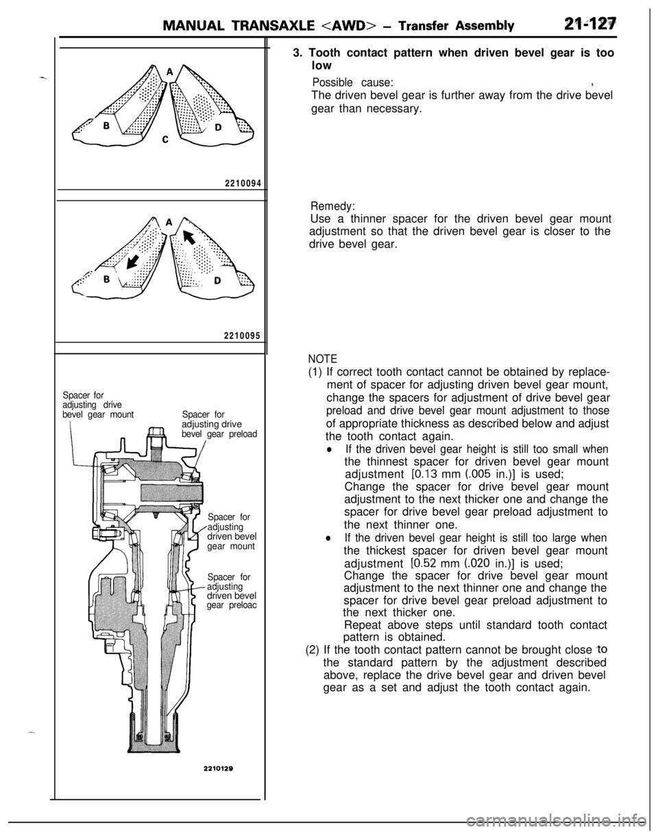
gear preloac3. Tooth contact pattern when driven bevel gear is too
low
Possible cause:,
The driven bevel gear is further away from the drive bevel
gear than necessary.
Remedy:Use a thinner spacer for the driven bevel gear mount
adjustment so that the driven bevel gear is closer to the
drive bevel gear.
NOTE(1) If correct tooth contact cannot be obtained by replace-
ment of spacer for adjusting driven bevel gear mount,
change the spacers for adjustment of drive bevel gear
preload and drive bevel gear mount adjustment to thoseof appropriate thickness as described below and adjust
the tooth contact again.
lIf the driven bevel gear height is still too small whenthe thinnest spacer for driven bevel gear mount
adjustment
[0.13 mm (.005 in.)] is used;
Change the spacer for drive bevel gear mount
adjustment to the next thicker one and change the
spacer for drive bevel gear preload adjustment to
the next thinner one.
lIf the driven bevel gear height is still too large whenthe thickest spacer for driven bevel gear mount
adjustment
[0.52 mm (020 in.)] is used;
Change the spacer for drive bevel gear mount
adjustment to the next thinner one and change the
spacer for drive bevel gear preload adjustment to
the next thicker one.
Repeat above steps until standard tooth contact
pattern is obtained.
(2) If the tooth contact pattern cannot be brought close
,tothe standard pattern by the adjustment described
above, replace the drive bevel gear and driven bevel
gear as a set and adjust the tooth contact again.
Page 1030 of 1216
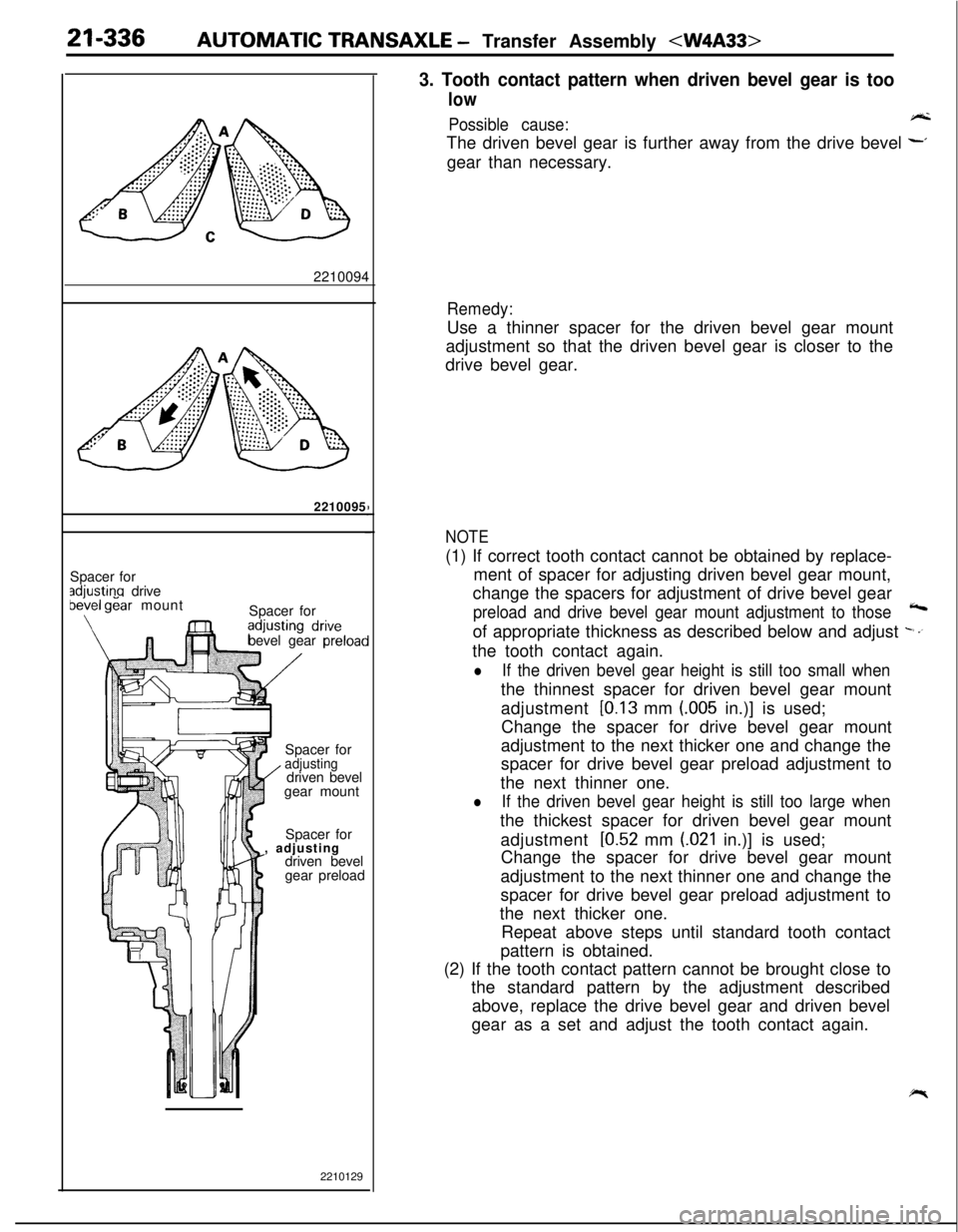
21-336AUTOMATIC TRANSAXLE - Transfer Assembly
2210095
Spacer for
adiustina drivebekel gear mount
\Spacer for
bevel gear preloacSpacer for
adjusting/ driven bevel
gear mount
Spacer for
, adjusting
driven bevel
gear preload
2210129
3. Tooth contact pattern when driven bevel gear is too
low
Possible cause:A-kThe driven bevel gear is further away from the drive bevel
~gear than necessary.
Remedy:Use a thinner spacer for the driven bevel gear mount
adjustment so that the driven bevel gear is closer to the
drive bevel gear.
NOTE(1) If correct tooth contact cannot be obtained by replace-
ment of spacer for adjusting driven bevel gear mount,
change the spacers for adjustment of drive bevel gear
preload and drive bevel gear mount adjustment to those4of appropriate thickness as described below and adjust
-.’the tooth contact again.
lIf the driven bevel gear height is still too small whenthe thinnest spacer for driven bevel gear mount
adjustment
[0.13 mm (.005 in.)] is used;
Change the spacer for drive bevel gear mount
adjustment to the next thicker one and change the
spacer for drive bevel gear preload adjustment to
the next thinner one.
lIf the driven bevel gear height is still too large whenthe thickest spacer for driven bevel gear mount
adjustment
[0.52 mm (021 in.)] is used;
Change the spacer for drive bevel gear mount
adjustment to the next thinner one and change the
spacer for drive bevel gear preload adjustment to
the next thicker one.
Repeat above steps until standard tooth contact
pattern is obtained.
(2) If the tooth contact pattern cannot be brought close to
the standard pattern by the adjustment described
above, replace the drive bevel gear and driven bevel
gear as a set and adjust the tooth contact again.
Page 1050 of 1216
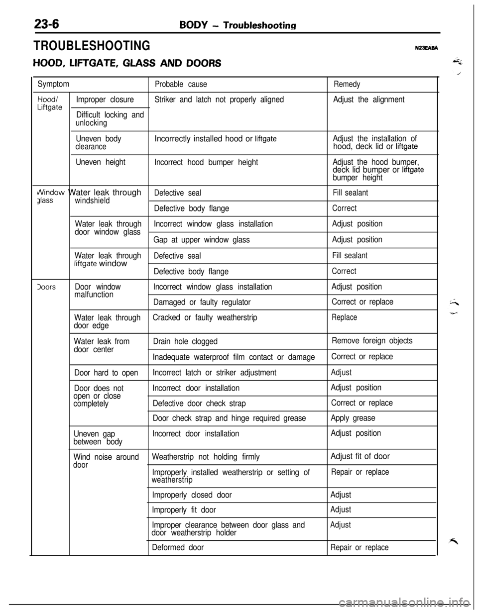
BODY - Troubleshooting
TROUBLESHOOTINGN23EFd
HOOD, LIFTGATE, GLASS AND DOORS
SymptomProbable causeRemedy
Hood/Improper closureStriker and latch not properly alignedAdjust the alignmentLiftgateDifficult locking and
unlocking
Uneven body
clearance
Uneven height
Incorrectly installed hood or liftgate
Incorrect hood bumper heightAdjust the installation of
hood, deck lid or liftgate
Adjust the hood bumper,deck lid bumper or liftgate
bumper height
i/\/indow Water leak throughDefective sealFill sealantJlasswindshield
Defective body flangeCorrect
Water leak throughIncorrect window glass installationAdjust position
door window glass
Gap at upper window glassAdjust position
Water leak through
Defective sealFill sealantliftgate window
Defective body flangeCorrect
IoorsDoor windowIncorrect window glass installationAdjust position
malfunction
Damaged or faulty regulatorCorrect or replace
Water leak throughCracked or faulty weatherstrip
Replace
door edge
Water leak fromDrain hole cloggedRemove foreign objects
door center
Inadequate waterproof film contact or damageCorrect or replace
Door hard to openIncorrect latch or striker adjustment
Adjust
Door does notIncorrect door installationAdjust position
open or close
completelyDefective door check strapCorrect or replace
Door check strap and hinge required greaseApply grease
Uneven gapIncorrect door installationAdjust position
between body
Wind noise aroundWeatherstrip not holding firmly
Adjust fit of door
doorImproperly installed weatherstrip or setting ofRepair or replace
weatherstrip
Improperly closed door
Improperly fit door
Improper clearance between door glass and
door weatherstrip holder
Deformed doorAdjust
Adjust
Adjust
Repair or replace