height MITSUBISHI ECLIPSE 1991 User Guide
[x] Cancel search | Manufacturer: MITSUBISHI, Model Year: 1991, Model line: ECLIPSE, Model: MITSUBISHI ECLIPSE 1991Pages: 1216, PDF Size: 67.42 MB
Page 232 of 1216
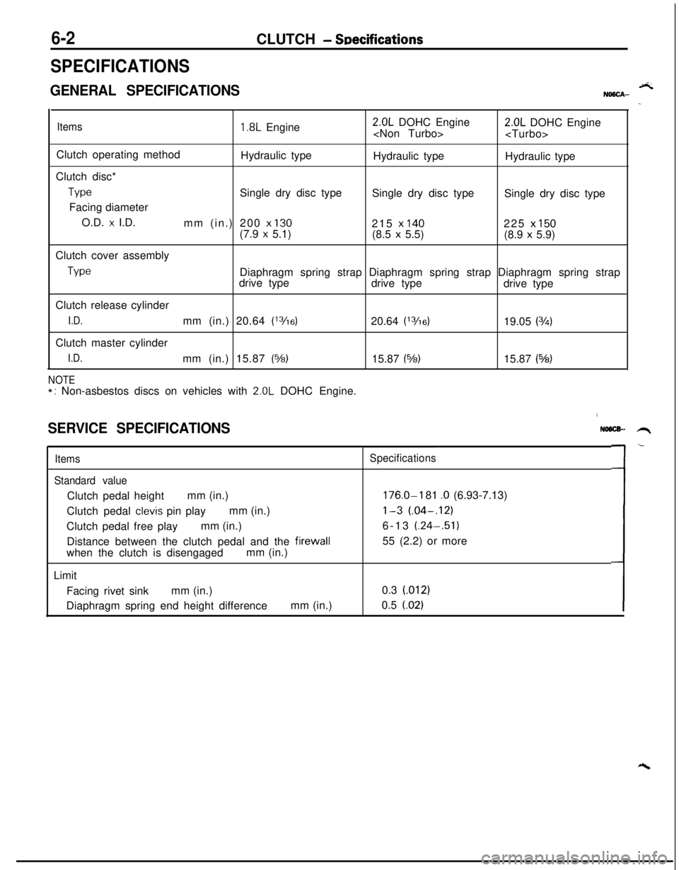
6-2CLUTCH - SDecifications
SPECIFICATIONS
GENERAL SPECIFICATIONS
Items1.8L Engine2.0L DOHC Engine
Clutch operating method
Hydraulic type
Hydraulic type
Hydraulic type
Clutch disc*
TypeSingle dry disc type
Single dry disc type
Single dry disc type
Facing diameter
O.D.
x I.D.
mm (in.) 200 x 130215 x 140225 x 150(7.9 x 5.1)
(8.5 x 5.5)
(8.9 x 5.9)
Clutch cover assembly
TypeDiaphragm spring strap Diaphragm spring strap Diaphragm spring strap
drive type
drive type
drive type
Clutch release cylinder
I.D.mm (in.) 20.64 (13/16)20.64 (13/6)19.05 (3h)Clutch master cylinder
I.D.mm (in.) 15.87 (%)15.87 (%)15.87 (543)
NOTE*: Non-asbestos discs on vehicles with 2.0L DOHC Engine.
SERVICE SPECIFICATIONS
Items
Standard valueClutch pedal heightmm (in.)
Clutch pedal
clevis pin playmm (in.)
Clutch pedal free playmm (in.)
Distance between the clutch pedal and the firewall
when the clutch is disengagedmm (in.)
Limit
Facing rivet sinkmm (in.)
Diaphragm spring end height differencemm (in.)
NO6lX- .H,
Specifications
176.0-I 81 .O (6.93-7.13)
l-3 (.04-.12)6-13 (.24-.51)
55 (2.2) or more
0.3 (012)
0.5
(.02)L-
Page 234 of 1216
6-4CLUTCH - Troubleshooting
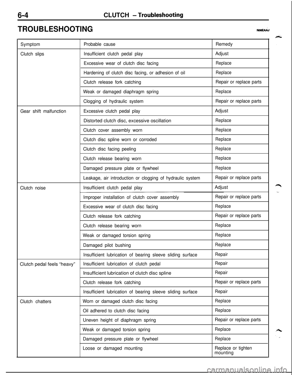
TROUBLESHOOTINGNO6hi.J
SymptomProbable causeRemedy
Clutch slipsInsufficient clutch pedal playAdjust
Excessive wear of clutch disc facingReplace
Hardening of clutch disc facing, or adhesion of oilReplace
Clutch release fork catchingRepair or replace parts
Weak or damaged diaphragm spring
Replace
Clogging of hydraulic systemRepair or replace parts
Gear shift malfunctionExcessive clutch pedal playAdjust
Distorted clutch disc, excessive oscillation
Replace
Clutch cover assembly wornReplace
Clutch disc spline worn or corrodedReplace
Clutch disc facing peelingReplace
Clutch release bearing wornReplace
Damaged pressure plate or flywheelReplace
Leakage, air introduction or clogging of hydraulic systemRepair or replace parts
Clutch noiseInsufficient clutch pedal playAdjust
Improper installation of clutch cover assemblyRepair or replace parts
Excessive wear of clutch disc facing
Replace
Clutch release fork catchingRepair or replace parts
Clutch release bearing worn
Replace
Weak or damaged torsion springReplace
Damaged pilot bushingReplace
Insufficient lubrication of bearing sleeve sliding surfaceRepairClutch pedal feels “heavy”
Insufficient lubrication of clutch pedalRepairInsufficient lubrication of clutch disc spline
Repair
Clutch release fork catchingRepair or replace parts
Insufficient lubrication of bearing sleeve sliding surface
Repair
Clutch chattersWorn or damaged clutch disc facingReplace
Oil adhered to clutch disc facingReplace
Uneven height of diaphragm springRepair or replace parts
Weak or damaged torsion spring
Replace
Damaged pressure plate or flywheelReplace
Loose or damaged mountingReplace or tighten
mounting
Page 235 of 1216
CLUTCH - Service Adjustment Procedures6-5Clutch pedal height
b
AClutch pedal clevis
pin play
08YO43Vehicles without
auto-cruise control
systemVehicles with
auto-cruise control
08A0025I
Clutch pedal free pIa\
08YO43
Distance between the
clutch pedal and thefirewall
when theclutch is disengaged
SERVICE ADJUSTMENT PROCEDURES
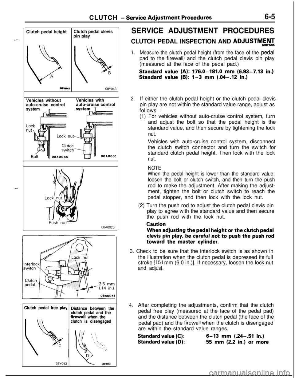
CLUTCH PEDAL INSPECTION AND ADJUSTMY’,
1.Measure the clutch pedal height (from the face of the pedalpad to the
firewall) and the clutch pedal clevis pin play
(measured at the face of the pedal pad.)
Standard value (A): 176.0-181.0 mm (6.93-7.13 in.)
Standard value (B): l-3 mm (.04-.12 in.)
2.If either the clutch pedal height or the clutch pedal clevis
pin play are not within the standard value range, adjust as
follows
:(1) For vehicles without auto-cruise control system, turn
and adjust the bolt so that the pedal height is the
standard value, and then secure by tightening the lock
nut.Vehicles with auto-cruise control system, disconnect
the clutch switch connector and turn the switch for
standard clutch pedal height. Then lock with the lock
nut.
NOTE
When the pedal height is lower than the standard value,
loosen the bolt or clutch switch, and then turn the pushrod to make the adjustment. After making the adjust-
ment, tighten the bolt or clutch switch to reach the
pedal stopper, and then lock with the lock nut.
(2) Turn the push rod to adjust the clutch pedal clevis pin
play to agree with the standard value and then secure
the push rod with the lock nut.
CautionWhen adjusting the
pedal height or the clutch pedal
clevis pin play, be careful not to push the push rodtoward the master
cylinder.3. Check to be sure that the interlock switch is as shown in
the illustration when the clutch pedal is depressed its full
stroke
[151 mm (6.0 in.)]. If necessary, loosen the lock nut
and adjust.
4.After completing the adjustments, confirm that the clutch
pedal free play (measured at the face of the pedal pad)
and the distance between the clutch pedal (the face of the
pedal pad) and the
firewall when the clutch is disengaged
are within the standard value ranges.
Standard value (C):6-13 mm (.24-.51 in.)
Standard value (D):55 mm (2.2 in.) or more
Page 247 of 1216
CLUTCH - Clutch Cover and Disc647
08A0038
6CLOO3SERVICE POINTS OF REMOVAL
NO6OSAH
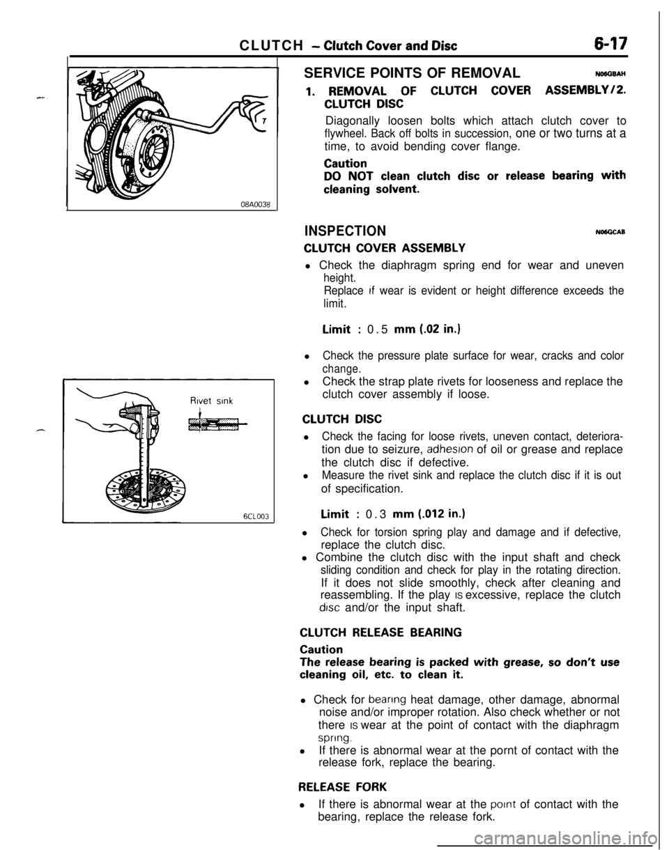
1. REMOVAL OF CLUTCH COVER ASSEMBLY/P.
CLUTCH DISCDiagonally loosen bolts which attach clutch cover to
flywheel. Back off bolts in succession, one or two turns at atime, to avoid bending cover flange.
Caution
DO NOT clean clutch disc or release bearing with
cleaning solvent.
INSPECTIONNlNGCAB
CLUTCH COVER ASSEMBLYl Check the diaphragm spring end for wear and uneven
height.
Replace
If wear is evident or height difference exceeds the
limit.Limit
: 0.5 mm (.02 in.)l
Check the pressure plate surface for wear, cracks and color
change.lCheck the strap plate rivets for looseness and replace the
clutch cover assembly if loose.
CLUTCH DISCl
Check the facing for loose rivets, uneven contact, deteriora-tion due to seizure,
adhesron of oil or grease and replace
the clutch disc if defective.
l
Measure the rivet sink and replace the clutch disc if it is outof specification.Limit
: 0.3 mm (.012 in.)l
Check for torsion spring play and damage and if defective,replace the clutch disc.
l Combine the clutch disc with the input shaft and check
sliding condition and check for play in the rotating direction.If it does not slide smoothly, check after cleaning and
reassembling. If the play IS excessive, replace the clutch
drsc and/or the input shaft.
CLUTCH RELEASE BEARING
Caution
The release bearing is packed with grease, so don’t use
cleaning oil, etc. to clean it.l Check for
beanng heat damage, other damage, abnormal
noise and/or improper rotation. Also check whether or not
there IS wear at the point of contact with the diaphragm
spring.lIf there is abnormal wear at the pornt of contact with the
release fork, replace the bearing.
RELEASE FORKlIf there is abnormal wear at the
pornt of contact with the
bearing, replace the release fork.
Page 264 of 1216
7-16COOLING - Thermostat
INSPECTIONy+w
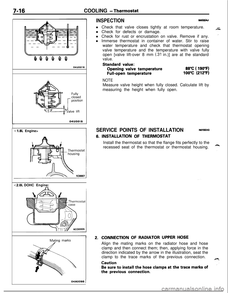
l Check that valve closes tightly at room temperature.
l Check for defects or damage.
l Check for rust or encrustation on valve. Remove if any.
l Immerse thermostat in container of water. Stir to raise
water temperature and check that thermostat opening
valve temperature and the temperature with valve fully
open [valve lift-over 8 mm
(.31 in.)] are at the standard
value.Standard
value:Opening
valve temperature
Full-open temperature
88°C ( 190°F)
100°C (212°F)
Fullyclosedpositionve lift
04UOO18<1.8L Engine><2.0L DOHCEngine:
IMating
marks
NOTEMeasure valve height when fully closed. Calculate lift by
measuring the height when fully open.
SERVICE POINTS OF INSTALLATIONNOlGEAG
6. INSTALLATION OF THERMOSTAT
Install the thermostat so that the flange fits perfectly to the
recessed seat of the thermostat or thermostat housing.
2.CONNECTION OF RADIATOR UPPER HOSEAlign the mating marks on the radiator hose and hose
clamp and then connect them; then, applying force in the
direction indicated by the arrow in the illustration, seat the
clamp to the trace marks of the previous connection.
Caution
Be sure to install the hose clamps at the trace marks ofthe
previous connection.
04A0099 )
Page 292 of 1216
9-8ENGINE - Specifications
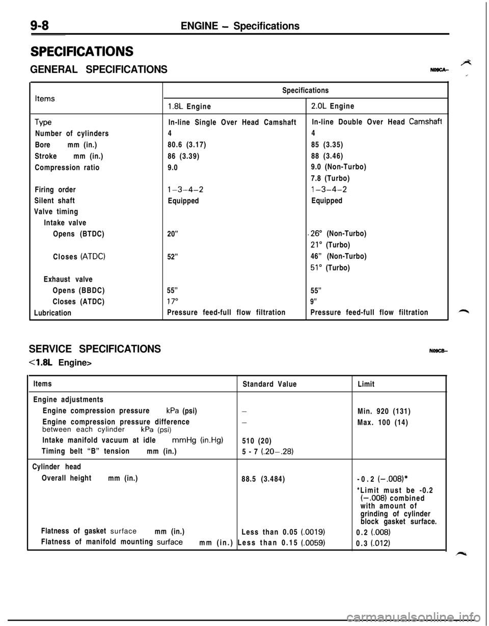
SPECIFICATIONS
GENERAL SPECIFICATIONSBNDBCA-
Items
TypeNumber of cylinders
Boremm (in.)
Strokemm (in.)
Compression ratio
Firing order
Silent shaft
Valve timing
Intake valve
Opens (BTDC)
Closes
(ATDC)Exhaust valve
Opens (BBDC)
Closes (ATDC)
LubricationSpecifications
1.8L Engine2.0L Engine
In-line Single Over Head CamshaftIn-line Double Over Head
Camshafi44
80.6 (3.17)85 (3.35)
86 (3.39)88 (3.46)
9.09.0 (Non-Turbo)
7.8 (Turbo)
l-3-4-21-3-4-2EquippedEquipped
20”
.26” (Non-Turbo)
21’ (Turbo)
52”46” (Non-Turbo)
51’ (Turbo)
55”
55”
17”9”Pressure feed-full flow filtrationPressure feed-full flow filtration
SERVICE SPECIFICATIONSNOSCB-
-4.8L Engine>
Items
Standard Value
Engine adjustments
Engine compression pressurekPa (psi)
-Engine compression pressure difference
-between each cylinder
kPa (psi)
Intake manifold vacuum at idle
mmHg (in.Hg)510 (20)
Timing belt “B” tension
mm (in.)
5-7
(.20-.28)Cylinder head
Overall height
mm (in.)
88.5 (3.484)
Flatness of gasket surface
mm (in.)
Less than 0.05
(0019)Flatness of manifold mounting
surfacemm (in.) Less than 0.15 (.0059)Limit
Min. 920 (131)
Max. 100 (14)
-0.2
(-.008)**Limit must be -0.2
(-.008) combined
with amount of
grinding of cylinder
block gasket surface.
0.2
(008)0.3
(.012)
Page 293 of 1216
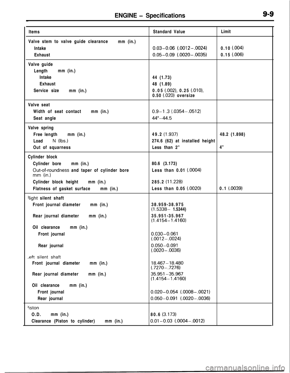
ENGINE - SpecificationsItems
Valve stem to valve guide clearance
Intake
Exhaust
Valve guide
Lengthmm (in.)
Intake
Exhaust
Service size
mm (in.)mm (in.)Standard Value
0.03-0.06 (.0012-.0024)
0.05-0.09 (.0020-.0035)44 (1.73)
48 (1.89)
0.05
(.002), 0.25 (.OlO),
0.50
i.020) oversizeLimit
0.10
f.004)0.15
i.006)Valve seat
Width of seat contactmm (in.)
Seat angle
Valve spring
Free lengthmm (in.)
Load
N (Ibs.)
Out of squarness
Cylinder block
Cylinder boremm (in.)
ZIut-of;yundness and taper of cylinder bore
Cylinder block heightmm (in.)
Flatness of gasket surfacemm (in.)qight silent shaft
Front journal diametermm (in.)
Rear journal diametermm (in.)
Oil clearancemm (in.)
Front journal
Rear journal
-eft silent shaft
Front journal diametermm (in.)
Rear journal diametermm (in.)
Oil clearancemm (in.)
Front journal
Rear journal
‘istonO.D.mm (in.)
Clearance (Piston to cylinder)mm (in.)
0.9-l .3 (.0354-.0512)
44”-44.549.2
(1.937)48.2 (1.898)
274.6 (62) at installed height
Less than 2”4”
80.6 (3.173)
Less than 0.01
(.0004)285.2
(11.228)Less than 0.05
(.0020)0.1 (.0039)38.959-38.975
(1.5338- 1.5344)
35.951-35.967
(1.4154- 1.4160)
0.030-0.061(.0012-.0024)
0.050-0.091(.0020- .0036)
18.467- 18.480(.7270- .7276)
35.951-35.967(1.4154-1.4160)
0.020-0.054 (.0008-.0021)
0.050-0.091 (.0020-.0036)80.6
(3.173)
0.01-0.03 (.0004-.0012)
Page 294 of 1216
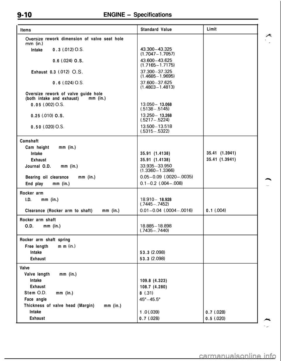
9-10ENGINE - SpecificationsItems
rIvrs,iz; rework dimension of valve seat hole
Intake0.3
(012) O.S.0.6
(024) O.S.
Exhaust 0.3
(.012) O.S.
0.6
(024) OS.Oversize rework of valve guide hole
(both intake and exhaust)mm (in.)
0.05
(.002) O.S.0.25
(.OlO) O.S.
0.50
(.020) O.S.Standard Value
43.300-43.325
(1.7047- 1.7057)
43.600-43.625
(1.7165-1.7175)
37.300-37.325(1.4685- 1.9695)
37.600-37.625(1.4803- 1.4813)
13.050- 13.068(.5138-.5145)
13.250- 13.268(.5217-.5224)
13.500-13.518
(.5315-.5322)Limit
Camshaft
Cam heightmm (in.)
Intake35.91 (1.4138)35.41 (1.3941)
Exhaust35.91 (1.4138)35.41 (1.3941)
Journal O.D.mm (in.)
33.935-33.950(1.3360- 1.3366)Bearing oil clearancemm (in.)
0.05-0.09 (.0020-.0035)End playmm (in.)
0.1-0.2 (.004-,008)Rocker arm
I.D.mm (in.)
18.910- 18.928
(.7445- .7452)Clearance (Rocker arm to shaft)mm (in.)
0.01-0.04 (.0004-.0016)0.1 (004)Rocker arm shaft
O.D.mm (in.)
18.885- 18.898(.7435-.7440)Rocker arm shaft spring
Free lengthmm (in.)
Intake
Exhaust
Valve
Valve lengthmm (in.)
Intake
Exhaust
Stem
O.D.mm (in.)
Face angle
Thickness of valve head (Margin)
Intake
Exhaust53.3
(2.098)53.3
(2.098)109.8 (4.323)
108.7 (4.280)
8
(.31)
45”-45.5”mm (in.)
1 .o
(.039)0.7 (028)0.7
(.028)0.5 (.020)
Page 297 of 1216
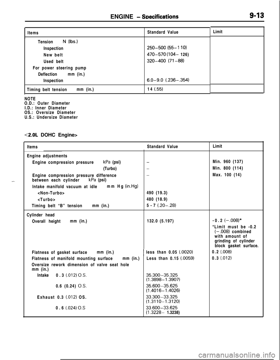
ENGINE - SDecificationsItems
TensionN (Ibs.)
Inspection
New belt
Used belt
For power steering pump
Deflectionmm (in.)
Inspection
Timing belt tensionmm (in.)Standard Value
250-500 (55-l 10)
470-570 (104- 126)
320-400 (71-88)
6.0-9.0 (.236-.354)14
(.55)NOTE
O.D.: Outer Diameter
I.D.: Inner Diameter
OS.: Oversize Diameter
U.S.: Undersize Diameter<2.0L DOHC Engine>
-ItemsStandard ValueLimit
Engine adjustments
Engine compression pressurekPa (psi)
(Turbo)
Engine compression pressure difference
between each cylinderkPa (psi)
Intake manifold vacuum at idlemm Hg
(in.Hg)
Timing belt “B” tensionmm (in.)
-
-
-490 (19.3)
480 (18.9)
5-7
(.20-.28)Cylinder head
Overall heightmm (in.)132.0 (5.197)
Flatness of gasket surfacemm (in.)
Flatness of manifold mounting surfacemm (in.)
Oversize rework dimension of valve seat hole
mm (in.)
Intake0.3
(.012) 0,s.0.6 (0.24)
0,s.Exhaust 0.3
(.012) OS.
0.6
(.024) 0.S~ less than 0.05
(.0020)Less than 0.15
(.0059)
35.300-35.325(1.3898-1.3907)
35.600-35.625
(1.4016-l .4026)
33.300-33.325(1.3110-1.3120)
33.600-33.625
(1.3228- 1.3238)Limit
Min. 960 (137)
Min. 800 (114)
Max. 100 (14)
-0.2
(-,008)”*Limit must be -0.2
(- .008) combined
with amount of
grinding of cylinder
block gasket surface.
0.2
(.008)0.3
(.012)
Page 298 of 1216
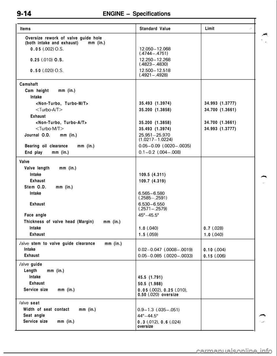
9-14ENGINE - SpecificationsItems
Oversize rework of valve guide hole
(both intake and exhaust)mm (in.)
0.05
(.002) O.S.0.25
(.OlO) O.S.
0.50
(.020) 0,s.Standard Value
12.050-12.068(.4744-.4751)
12.250-12.268(.4823-.4830)
12.500-12.518
(.4921-.4928)Limit
,’Camshaft
Cam heightmm (in.)
Intake
Exhaust
Journal O.D.mm (in.)
25.951-25.970(1.0217-1.0224)Bearing oil clearancemm (in.)
0.05-0.09 (.0020-.0035)End playmm (in.)
0.1-0.2 (.004-,008)Valve
Valve lengthmm (in.)
Intake
109.5 (4.311)
Exhaust
109.7 (4.319)
Stem O.D.mm (in.)
Intake
6.565-6.580(.2585-.2591)Exhaust
6.530-6.550
(.2571-.2579)Face angle
45"-45.5"Thickness of valve head (Margin)
mm (in.)
Intake
1.0
(.040)0.7 (.028)Exhaust
1.5
(.059)1.0 (.040)Jalve stem to valve guide clearance
mm (in.)
Intake
0.02-0.047 (.0008-.0019)0.10 (.004)Exhaust
0.05-0.085 (.0020-.0033)0.15 (.006)Jalve guide
Length
mm (in.)
Intake
45.5 (1.791)
Exhaust
50.5 (1.988)
Service size
mm (in.)
0.05
(.002), 0.25 (.OlO),0.50 (.020) oversize
/alve seat
Width of seat contact
mm (in.)
0.9-1.3 (.035-.051)Seat angle
44"-44.5"Service size
mm (in.)
0.3
(.012), 0.6 (.024)oversize