brake sensor MITSUBISHI ECLIPSE 1991 Workshop Manual
[x] Cancel search | Manufacturer: MITSUBISHI, Model Year: 1991, Model line: ECLIPSE, Model: MITSUBISHI ECLIPSE 1991Pages: 1216, PDF Size: 67.42 MB
Page 615 of 1216
REAR SUSPENSION
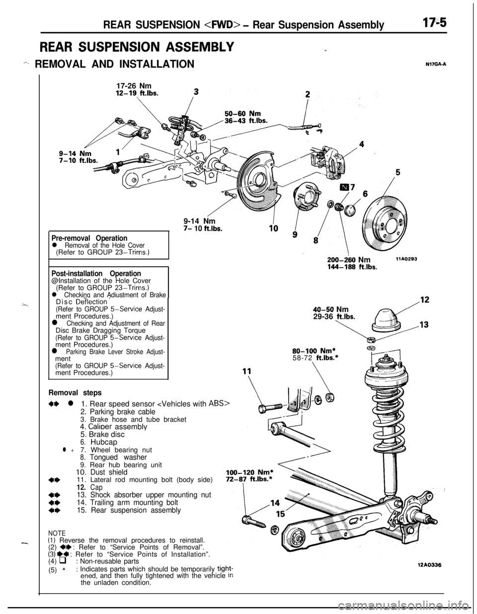
REAR SUSPENSION ASSEMBLYu
-%. REMOVAL AND INSTALLATIONN17GAA
---i
--..17-26 Nm12-19
ft.lbs.9-14 Nm
7- 10 ft.lbs.
Pre-removal Operationl Removal of the Hole Cover(Refer to GROUP 23-Trims.)
Post-installation Operation@Installation of the Hole Cover
(Refer to GROUP
23-Trims.)l Checking and Adiustment of BrakeDisc De‘ilection ’(Refer to GROUP 5-Service Adjust-ment Procedures.)
l Checking and Adjustment of RearDisc Brake Dragging Torque
(Refer to GROUP &Service Adjust-ment Procedures.)
l Parking Brake Lever Stroke Adjust-ment
(Refer to GROUP 5-Service Adjust-ment Procedures.)
Removal steps
W l1. Rear speed sensor
2. Parking brake cable3. Brake hose and tube bracket
4.
Calioer assemblv
200-280 Nm144-168 ftlbs.
llAO293
40-50 Nm
29-36 ltlbs.80-100
Nm*58-72 ft.lbs.*5. Brake disc
’6.Hubcapl +7. Wheel bearing nut8.Tongued washer9. Rear hub bearing unit
10.Dust shield
4*11. Lateral rod mounting bolt (body side)12.Cap
t:
13. Shock absorber upper mounting nut
14. Trailing arm mounting bolt
4*15. Rear suspension assembly
NOTE(I) Reverse the removal procedures to reinstall.
(2) +e : Refer to “Service Points of Removal”.(31 ~~ : Refer to “Service Points of Installation”.
(4) q : Non-reusable parts
(5)
*: Indicates parts which should be temporarily tight-ened, and then fully tightened with the vehicle Inthe unladen condition.12AO336
Page 622 of 1216
17-12REAR SUSPENSION
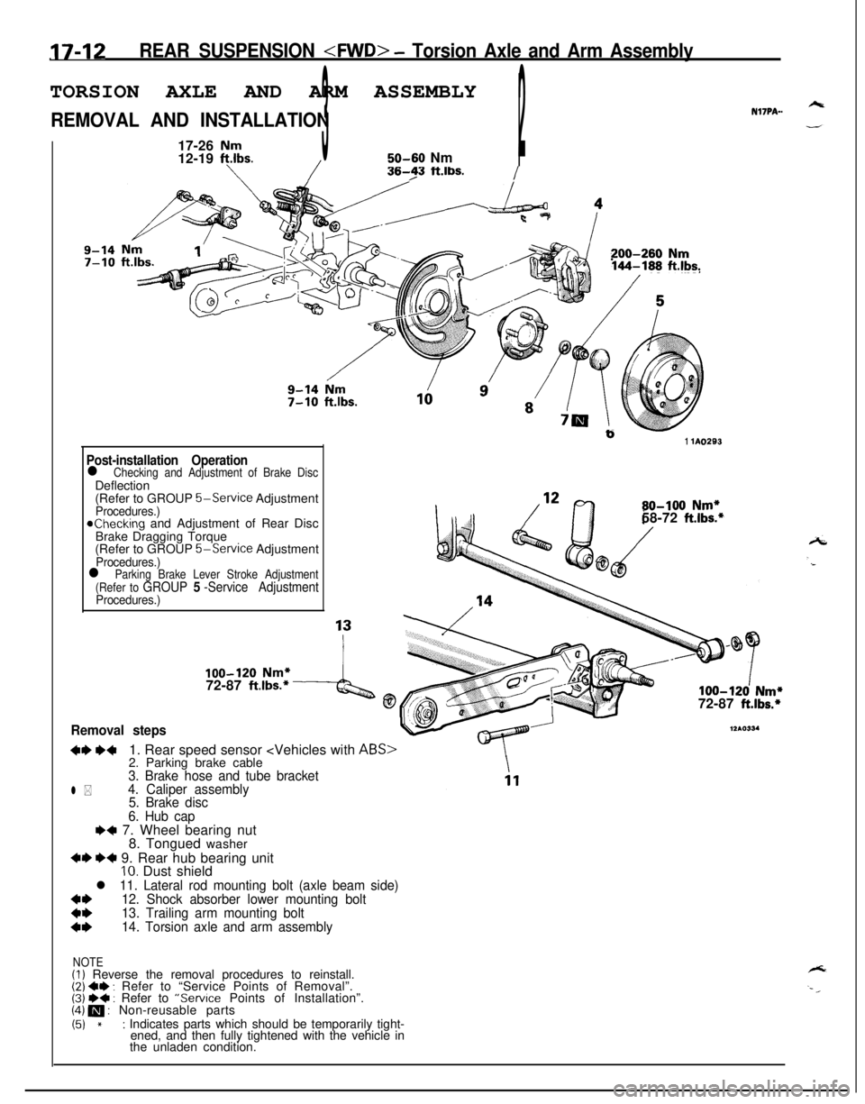
REMOVAL AND INSTALLATIONNl’IPA-.
17-26
Nm12-19 ft.lbs.350-60 Nm2/I
/36-23 ft.lbs./
Nm1’200-260 Nm144-188 ft.lbs.
b1 lA0293
Post-installation Operationl Checking and Adjustment of Brake DiscDeflection
(Refer to GROUP
5-Service AdjustmentProcedures.)achecking and Adjustment of Rear Disc
Brake Dragging Torque
(Refer to GROUP
5-Service AdjustmentProcedures.)
80-100 Nm*58-72 ft.lbs.*
l Parking Brake Lever Stroke Adjustment
(Refer to GROUP 5 -Service AdjustmentProcedures.)
100-120 Nm*72-87 ft.lbs.*4@100-120 Nm*72-87 ft.lbs.*
Removal steps
+I) ++1. Rear speed sensor
12*0334
l *
3. Brake hose and tube bracket
4. Caliper assembly
5. Brake disc
6. Hub cap
e+ 7. Wheel bearing nut
8. Tongued washer
+I) *+ 9. Rear hub bearing unitIO. Dust shield
l 11. Lateral rod mounting bolt (axle beam side)
*I)12. Shock absorber lower mounting bolt
13. Trailing arm mounting bolt
14. Torsion axle and arm assembly
NOTE(I) Reverse the removal procedures to reinstall.(2) ~~ : Refer to “Service Points of Removal”.(3j W+ : Refer to “Service Points of Installation”.(4) m : Non-reusable parts
(51 *: Indicates parts which should be temporarily tight-
ened, and then fully tightened with the vehicle in
the unladen condition.
Page 624 of 1216
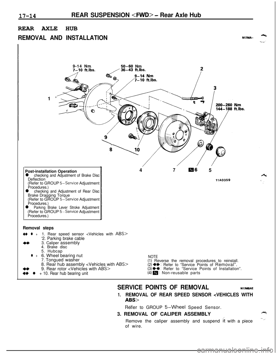
17-14REAR SUSPENSION
REMOVAL AND INSTALLATIONNl’IMA--1’9-14 Nm
50-60 Nm
Post-installation Operation
l checking and Adjustment of Brake DiscDeflection
(Refer to GROUP
5-Service AdjustmentProcedures.)l checking and Adjustment of Rear DiscBrake Dragging Torque
(Refer to GROUP
5-Service AdjustmentProcedures.)l Parking Brake Lever Stroke Adjustment(Refer to GROUP 5%Service AdjustmentProcedures.)
47m6 5
llA0359
Removal steps
+* l +1. Rear speed sensor
‘2. Parking brake cable
4*3. Caliper assembly
4. Brake disc
5. Hubcap
l +6. Wheel bearing nut
7. Tongued washer
8. Rear hub assembly
4*9. Rear rotor
+I) l + 10. Rear hub bearing unit
NOTE(I) Reverse the removal procedures to reinstall.(2) +e : Refer to “Service Points of Removal”.(3) I)+ : Refer to “Service Points of Installation”.(4) m : Non-reusable parts
SERVICE POINTS OF REMOVALNVMBAE
1.REMOVAL OF REAR SPEED SENSOR
R6fer to GROUP 5-Wheel Speed Sensor.
3. REMOVAL OF CALIPER ASSEMBLY
Remove the caliper assembly and suspend
it with a piece
of wire.
Page 627 of 1216
REAR SUSPENSION
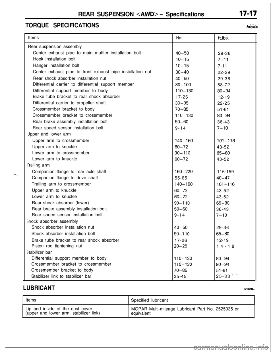
TORQUE SPECIFICATIONS. ‘2 +’ iiNl?GGbItems
Rear suspension assembly
Center exhaust pipe to main muffler installation bolt
Hook installation bolt
Hanger installation bolt
Center exhaust pipe to front exhaust pipe installation nut
Rear shock absorber installation nut
Differential carrier to differential support member
Differential support member to body
Brake tube bracket to rear shock absorber
Differential carrier to propeller shaft
Crossmember bracket to body
Crossmember bracket to crossmember
Rear brake assembly installation bolt
Rear speed sensor installation bolt
Jpper and lower arm
Upper arm to crossmember
Upper arm to knuckle
Lower arm to crossmember
Lower arm to knuckle
[railing arm
Companion flange to rear axle shaft
Companion flange to drive shaft
Trailing arm to crossmember
Upper arm to knuckle
Lower arm to knuckle
Rear shock absorber (lower)
Rear brake assembly installation bolt
Rear speed sensor installation bolt
Ghock absorber assembly
Shock absorber installation nut
Shock absorber installation bolt
Brake tube bracket to rear shock absorber
Piston rod tightening nut
stabilizer bar
Differential support member to body
Crossmember bracket to crossmember
Crossmember bracket to body
Stabilizer link to stabilizer bar
Nmft.lbs.
40-5029-36
IO-157-ii
IO-157-11
30-4022-29
40-5029-36
80-10058-72
110-13080-9417-26
12-19
30-3522-25
70-8551-61
110-13080-94
50-6036-43
9-14
7-10
140-160101-116
60-7243-52
90-I 1065-80
60-7243-52
160-220116-159
55-65
40-47
140-160101-116
60-7243-52
60-7243-52
90-I 1065-80
50-6036-43
9-14
7-10
40-5029-36
90-l 1065-8017-2612-19
20-2514-18
110-13080-94
110-13080-94
70-8551-61
35-4525-33
I'-'.
LUBRICANTNl’ICD-
ItemsSpecified lubricant
Lip and inside of the dust cover
(upper and lower arm, stabilizer link)MOPAR Multi-mileage Lubricant Part No. 2525035 or
equivalent
Page 632 of 1216
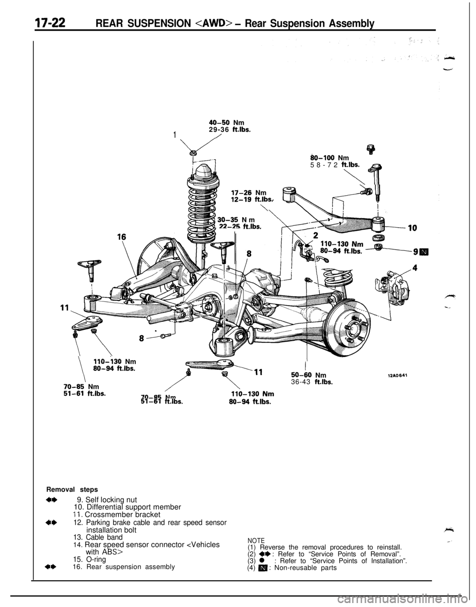
17-22REAR SUSPENSION
40-50 Nm
129-36 ft.lbs./
80-100 Nm
58-72 fiq T
i) 30-35 Nm,22-25 ftlbs.-- -- .-._--.I
17-26 Nm
t
12-19 ft.lbs.\
\
llO-i30 Nm80-94 ft.lbs.
70-85’ Nm51-61ftlbs.
I50-60Nm
36-43 ft.lbs.
70-85Nm51-61ft.lbs.80-94ftlbs.
12AO641Removal steps
+*9. Self locking nut
10. Differential support member
11. Crossmember bracket
4*12. Parking brake cable and rear speed sensorinstallation bolt
13. Cable band
4*14. Rear speed sensor connector
ABS15. O-ring16. Rear suspension assembly
NOTE(1) Reverse the removal procedures to reinstall.
(2)
+e : Refer to “Service Points of Removal”.
(3) l : Refer to “Service Points of Installation”.
(4) a : Non-reusable parts
Page 633 of 1216
REAR SUSPENSION
14AO520
12AOlOQ
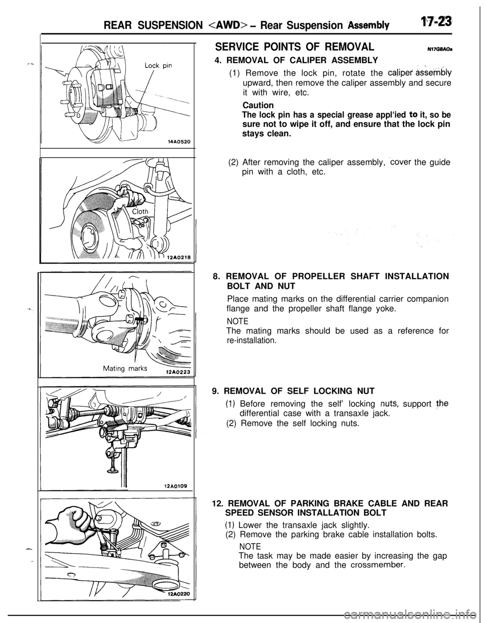
SERVICE POINTS OF REMOVALN17GQAOa4. REMOVAL OF CALIPER ASSEMBLY
(1) Remove the lock pin, rotate the calipei
&&e-@blyupward, then remove the caliper assembly and secure
it with wire, etc.
Caution
The lock pin has a special grease appl‘ied tq it, so besure not to wipe it off, and ensure that the lock pin
stays clean.
(2) After removing the caliper assembly,
.cover the guide
pin with a cloth, etc.
8. REMOVAL OF PROPELLER SHAFT INSTALLATION
BOLT AND NUT
Place mating marks on the differential carrier companion
flange and the propeller shaft flange yoke.
NOTEThe mating marks should be used as a reference for
re-installation.9. REMOVAL OF SELF LOCKING NUT
(1) Before removing the self’ locking nuts, support the
differential case with a transaxle jack.
(2) Remove the self locking nuts.
12. REMOVAL OF PARKING BRAKE CABLE AND REAR
SPEED SENSOR INSTALLATION BOLT
(1) Lower the transaxle jack slightly.
(2) Remove the parking brake cable installation bolts.
NOTEThe task may be made easier by increasing the gap
between the body and the
crossmember.
Page 638 of 1216
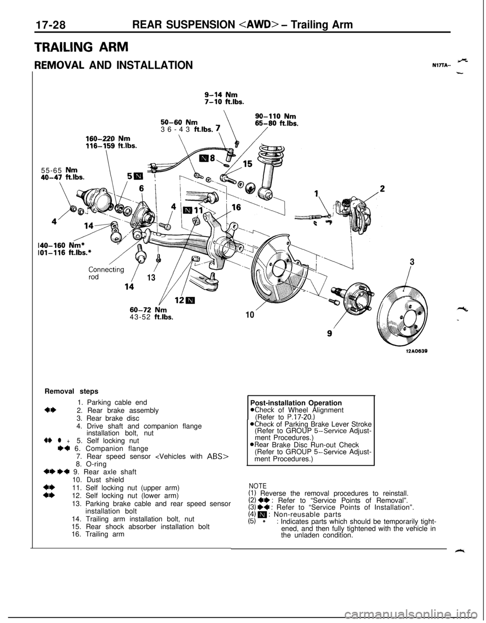
17-28REAR SUSPENSION
TRAILING ARMr
{EMOVAL AND INSTALLATION
9-14 Nm7-10 ft.lbs.
\SO-110
Nm50-60 Nm36-43 ft.lbs. !65-80 ftlbs.
/160-220 Nm\\\ /zdnnecting
/
/
13
_-_ --- .~~~~116-159 ftlbs.55-65
Nm40-47 ft.lbs.5m
60-72 Nrn43-52 ft.lbs.
/-\
103Removal steps
1. Parking cable end
4*2. Rear brake assembly
3. Rear brake disc
4. Drive shaft and companion flange
installation bolt, nut4I)
l +5. Self locking nut++ 6. Companion flange
7. Rear speed sensor
+I) ++ 9. Rear axle shaft
10. Dust shield
::11. Self locking nut (upper arm)
12. Self locking nut (lower arm)
13. Parking brake cable and rear speed sensor
installation bolt
14. Trailing arm installation bolt, nut
15. Rear shock absorber installation bolt
16. Trailing arm
12A0639Post-installation Operation
Kheck of Wheel Alignment
(Refer to P.17-20.)@Check of Parking Brake Lever Stroke
(Refer to GROUP 5-Service Adjust-
ment Procedures.)
@Rear Brake Disc Run-out Check
(Refer to GROUP 5-Service Adjust-
ment Procedures.)
NOTE(I) Reverse the removal procedures to reinstall.(2) ++ : Refer to “Service Points of Removal”.(3) W : Refer to “Service Points of Installation”.(4) m : Non-reusable parts(5) *: Indicates parts which should be temporarily tight-
ened, and then fully tightened with the vehicle in
the unladen condition.
9%NlTTA-
“c
_
k.
Page 645 of 1216
-.
J-
REAR SUSPENSION
STABILIZER BAR:_-REMOVAL AND INSTALLATION/rq7lA-i.i;: 112AO620
70-85 Nm110-130 Nm51-81 ft.lbs.80-94 ftlbs.9-14 Nm
7-10 ft.lbs./4
IL-v \
‘3w35-45 Nm
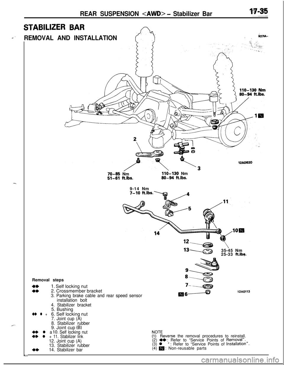
25-33 ft.lbg.Removal steps
::
1. Self locking nut
2. Crossmember bracket‘----e212A01133. Parking brake cable and rear speed sensormeA
installation bolt
4. Stabilizer bracket5. Bushing
+e l +6. Self locking nut7. Joint cup (A)
8. Stabilizer rubber9. Joint cup
(B)+e l a 10. Self locking nut++ l + 11. Stabilizer link!ykeverse the removal procedures to reinstall.
12. Joint cup (A)(2) +I) : Refer to “Service Points of Removyl”.
13. Stabilizer rubber(3) l * : Refer to “Service Points of Installation”.
4*14. Stabilizer bar(4) m : Non-reusable parts
L
Page 695 of 1216
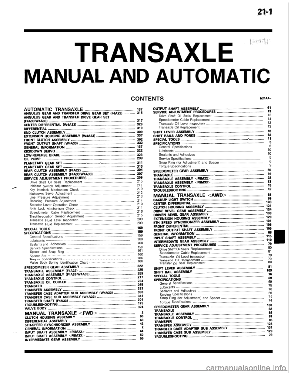
TRANSAXLE ’
MANUAL AND AUTOMATICCONTENTS
;-AUTOMATICTRANSAXLE
.....................................................137ANNULUS GEAR AND TRANSFER DRIVE GEAR SET (F4A22)..........315ANNULUS GEAR AND TRANSFER DRIVE GEAR SET(F4A33.W4A33)...........................................................................................317CENTERDIFFERENTIAL(W4A33).............................................................329DIFFERENTIAL............................................................................................319ENDCLUTCHASSEMBLY.........................................................................309EXTENSIONHOUSINGASSEMBLY(W4A33).........................................337FRONTCLUTCHASSEMBLY....................................................................302FRONTOUTPUTSHAFT(W4A33)...........................................................332GENERALINFORMATION.........................................................................137KICKDOWNSERVO....................................................................................322LOW-REVERSEBRAKE..............................................................................323OILPUMP...................................................................................................299PLANETARYGEARSET............................................................................311PLANETARYGEARSET............................................................................313REARCLUTCHASSEMBLY(F4A22)........................................................304REARCLUTCHASSEMBLY(FQA33sW4A33)............................................307SERVICEADJUSTMENTPROCEDURES..................................................Drive
Shaft,OilSealsReplacement....................................................;;;
InhibitorSwtchAdjustment................................................................21 1KeyInterlockMechanismCheck.....................................................KrckdownServoAdjustment..................................zii..............................
LinePressureAdjustment...................................................................213
ReducingPressureAdjustment.........................................................214Selector Lever Operation Check........................................................210ShiftLockMechanismCheck...............................................................21 1SpeedometerCableReplacement.........................................................Throttle-posltipn Sensor Adjustment.................................................z2:
TransaxleFluIdLevelInspectIon......................................................209
TransaxleFluidReplacement.............................................................209
SPECIALTOOLS.........................................................................................SPECIFICATIONS........................................................................................;“5”9
GeneralSpeclficatlons..................................................................1%Lubricants..................................................................................Sealants and Adhesives..............................................................izi
Serwce Speclflcatlons..................................................159...............Spacer andSnapRing.,.,.............................................................Spacer Set..................................................................1::Torque Speclflcatlons...........................................166Valve Body Spring Identification Chart.....................
.................160
SPEEDOMETERGEARASSEMBLY..........................................................TRANSAXLEASSEMBLY(WA22)............................................................zTRANSAXLE
ASSEMBLY(F4A33.W4A33)................................................TRANSAXLECONTROL.............................................................................;;;TRANSAXLE
OILCOOLER........................................................................TRANSFER..................................................................................................fg
TRANSFERASSEMBLY.............................................................................333TRANSFERCASEADAPTERSUBASSEMBLY(W4A33).......................339TRANSFER CASE SUB ASSEMBLY (W4A33)341TRANSFER SHAFT (F4A33)TROUBLESHOOTING..................................................................................................................................................................................................f;;VALVE
BODY.............................................................................................324
MANUAL TRANSAXLE
5TH-SPEEDSYNCHRONIZERASSEMBLY...............................................42GENERALINFORMATION.........................................................................2.-.INPUTfj,-,A,TASSEMBLY
INTERMEDIATE GEAR ASSEMBLY..........................................................56OUTPUT
SHAFT ASSEMBLY....................................................................61SERVICEADJUSTMENTPROCEDURES..................................................DriveShaftOilSealsReplacement......................................................;;Speedometer Cable Replacement.........................................................
Transaxle Oil Level
InspectIon..............................................................‘liTransaxle Oil Replacement....................................................................
I3
SHIFTLEVERASSEMBLY.........................................................................SHIFTRAILSANDFORKS........................................................................g
SPECIALTOOLS.........................................................................................SPECIFICATIONS........................................................................................1:
General Specifications5Lubricants..........................................................................................................................................................................10Sealants and Adhesives
Service Specifications
....................................................................................................................................................1:Snap Ring (for Adjustment) and Spacer...............................................
Torque Specifications.............................................................................
i
SPEEDOMETERGEARASSEMBLY..........................................................TRANS&G.E................................................................................................zTRANSAXLEA!jSEMBLY
TROUBLESHOOTING..................................................................................12
MANUAL TRANSAXLE
CENTERDIFFERENTIAL.............................................................................103CLUTCHHOUSINGASSEMBLY...............................................................DRIVE BEVEL GEAR ASSEMBLY;g
...... .......................................................DRIVENBEVELGEARASSEMBLY...................................a......................EXTENSIONHOUSINGASSEMBLY.........................................................;g
5Tf.jSPEEDSYNCHRONIZERASSEMBLY...............................................101
FRONTDlFFERENTlAL...............................................................................106
FRONTOUTPUTSHAFTASSEMBLY......................................................106
GENERALI~~~~MATN)N...............................................................,.,.......66INPUTSHAFTASSEMBLY........................................................................l~ER,“,EDlATEGEARASSMBLY..........................................................;;i
SERVICEADJUSTMENTPROCEDURES..................................................Drive Shaft Oil Seals Replacement......................................................;;Speedometer Cable Replacement.........................................................
Transaxle
Ojl Level lnspectlon..............................................................;l
Transaxle 011 R~pb33ment....................................................................79Transfer
OilSealReplacement.............................................................80
SHIFTLEVERASSEMBLY.........................................................................SHIFTRAILASSEMBLY............................................................................,z
SPECIALTOOLS.........................................................................................76
SPECIFICATIONS........................................................................................6g
GeneralSpecifications...........................................................................6g
Lubricants...............................................................................................75
SealantsandAdhesives........................................................................76
ServiceSpecifications............................................................................6gSnap Ring (for Adjustment) and Spacer...............................................7 o
TorqueSpecifications.............................................................................74
SPEEDOMETERGEARASSEMBLY..........................................................TRANSAXLE................................................................................................1:TRANSAXLEASSEMBLY...........................................................................86TRANSAXLE
CONTROL
.............................................................................TRANSFER...............................................................................................
g.._TRANSFERA!333lBLY.............................................................................,24
TRANSFERCASEADAPTERSUBASSEMBLY.......................................131TRANSFERCASESUBASSEMBLY.........................................................TR,,UBLES,,OO,,NG..................................................................................1;;
Page 869 of 1216
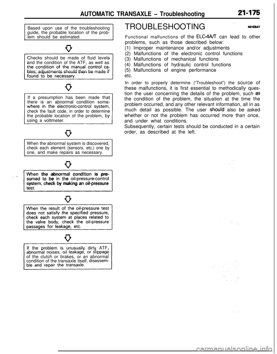
AUTOMATIC TRANSAXLE - TroubleshootingBased upon use of the troubleshooting
guide, the probable location of the prob-
lem should be estimated.
Checks should be made of fluid levels
and the condition of the ATF, as well as
bles; adjustments should then be made if
If a presumption has been made that
there is an abnormal condition some-
check the fault code, in order to determinethe probable location of the problem, by
When the abnormal system is discovered,
check each element (sensors, etc.) one byone, and make repairs as necessary.
“~^II_When the abnormal condition is pre-
sumed to be in the
orI-pressure-controlsystem, check by making an oil-pressure
If the problem is unusually dirty ATF,
of the clutch or brakes, or an abnormal
condition of the transaxle itself,
disassem-TROUBLESHOOTING
”N21EeAYFunctional malfunctions of the ELC4A/T can lead to other
problems, such as those described below:
(1) Improper maintenance and/or adjustments
(2) Malfunctions of the electronic control functions
(3) Malfunctions of mechanical functions
(4) Malfunctions of hydraulic control functions
(5) Malfunctions of engine performance
etc.In order to properly determine (“Troubleshoot”) the source of
these malfunctions, it is first essential to methodically ques-
tion the user concerning the details of the problem, such qs
the condition of the problem, the situation at the time the
problem occurred, and any other relevant information, all in as
much detail as possible. The user
shoutd also be asked
whether or not the problem has occurred more than once,
and under what conditions.
Subsequently, certain tests should be conducted in a certain
order, as described at the left.