differential MITSUBISHI ECLIPSE 1991 Service Manual
[x] Cancel search | Manufacturer: MITSUBISHI, Model Year: 1991, Model line: ECLIPSE, Model: MITSUBISHI ECLIPSE 1991Pages: 1216, PDF Size: 67.42 MB
Page 20 of 1216
20INTRODUCTION AND MASTER TROUBLESHOOTING - Towing and Hoisting
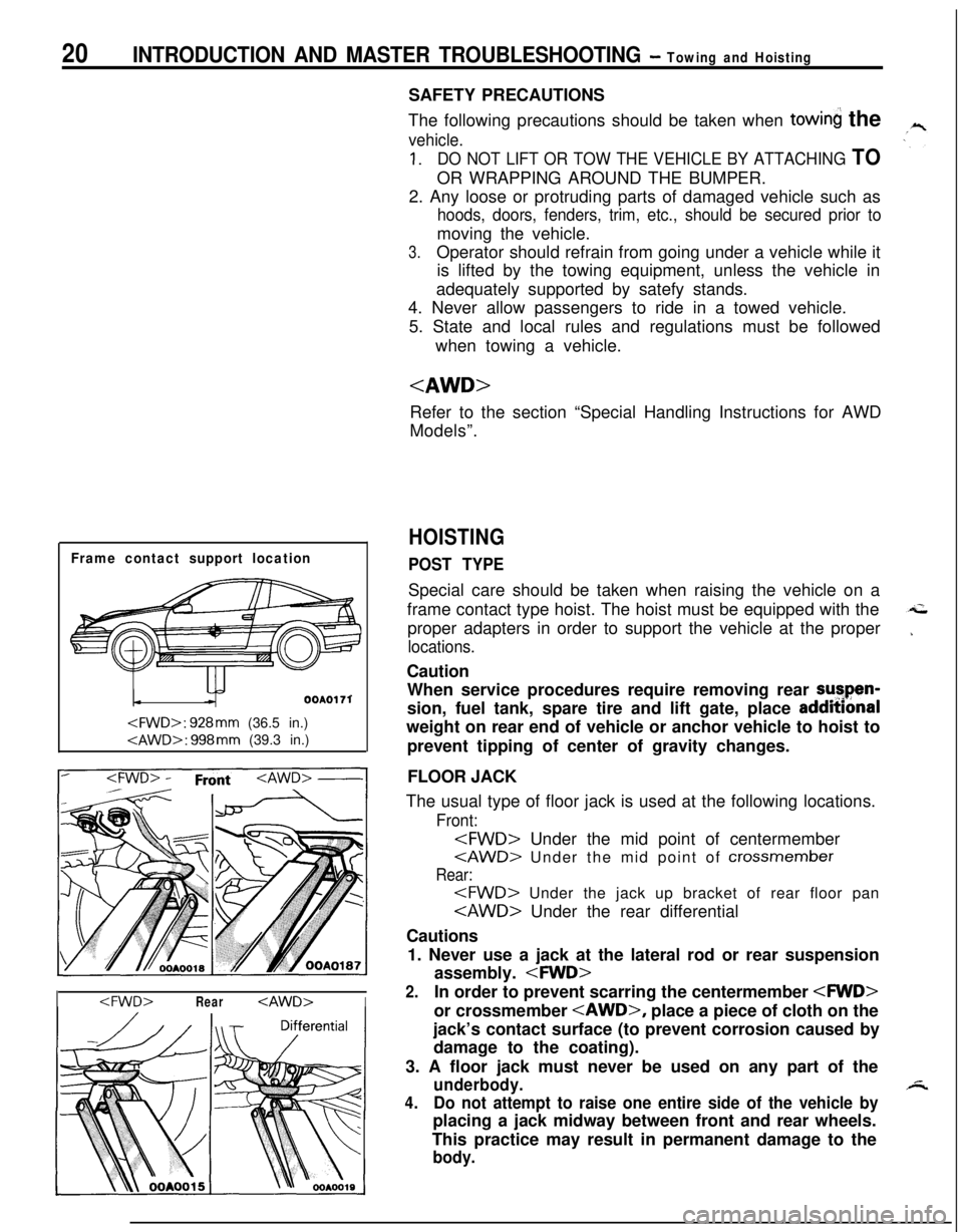
Frame contact support location
OOAOI 71
I
The following precautions should be taken when
towin the
vehicle.
1.DO NOT LIFT OR TOW THE VEHICLE BY ATTACHING TOOR WRAPPING AROUND THE BUMPER.
2. Any loose or protruding parts of damaged vehicle such as
hoods, doors, fenders, trim, etc., should be secured prior tomoving the vehicle.
3.Operator should refrain from going under a vehicle while it
is lifted by the towing equipment, unless the vehicle in
adequately supported by satefy stands.
4. Never allow passengers to ride in a towed vehicle.
5. State and local rules and regulations must be followed
when towing a vehicle.
Refer to the section “Special Handling Instructions for AWD
Models”.
HOISTING
POST TYPESpecial care should be taken when raising the vehicle on a
frame contact type hoist. The hoist must be equipped with the
proper adapters in order to support the vehicle at the proper
locations.Caution
When service procedures require removing rear sutpen-
sion, fuel tank, spare tire and lift gate, place addmonal
weight on rear end of vehicle or anchor vehicle to hoist to
prevent tipping of center of gravity changes.
FLOOR JACK
The usual type of floor jack is used at the following locations.
Front:
Rear:
Cautions
1. Never use a jack at the lateral rod or rear suspension
assembly.
2.In order to prevent scarring the centermember
jack’s contact surface (to prevent corrosion caused by
damage to the coating).
3. A floor jack must never be used on any part of the
underbody.
4.Do not attempt to raise one entire side of the vehicle byplacing a jack midway between front and rear wheels.
This practice may result in permanent damage to the
body.
Page 37 of 1216
LUBRICATION AND MAINTENANCE - Scheduled MaintenanCe Table. &3
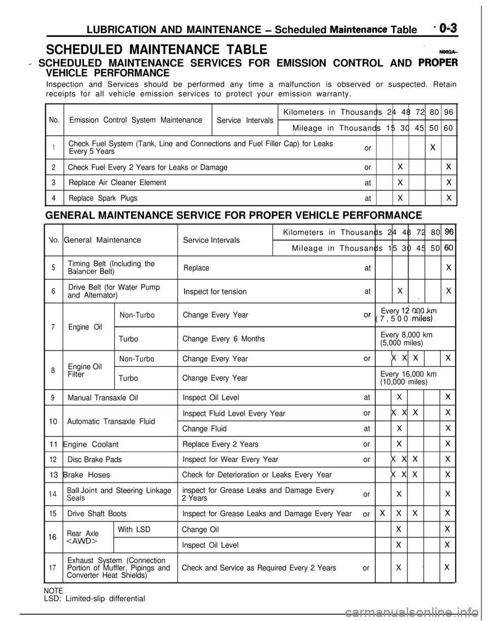
SCHEDULED MAINTENANCE TABLE1
- SCHEDULED MAINTENANCE SERVICES FOR EMISSION CONTROL AND PRO;;
VEHICLE PERFORMANCEInspection and Services should be performed any time a malfunction is observed or suspected. Retain
receipts for all vehicle emission services to protect your emission warranty.
Kilometers in Thousands 24 48 72 80 96
No.Emission Control System Maintenance
Service IntervalsMileage in Thousands 15 30 45 50 60
1Check Fuel System (Tank, Line and Connections and Fuel Filler Cap) for Leaks
Every 5 YearsorX
2Check Fuel Every 2 Years for Leaks or DamageorXX
3Replace Air Cleaner Element
atXX
4Replace Spark Plugs
atXXGENERAL MAINTENANCE SERVICE FOR PROPER VEHICLE PERFORMANCE
Yo. General Maintenance
Service IntervalsKilometers in Thousands 24 48 72 80 9cMileage in Thousands 15 30 45 50
6C
5Timing Belt (Including theBalancer Belt)ReplaceatX
6Drive Belt (for Water Pump
and Alternator)Inspect for tensionatXX.’
Non-TurboChange Every YearEvery 12 000 kmOr (7,500 miles).
7Engine Oil
TurboChange Every 6 MonthsEvery 8,000 km
(5,000 miles)
Non-TurboChange Every Yearor X X XX
8Engine Oil
Filter
TurboChange Every YearEvery 16,000 km
(10,000 miles)
9Manual Transaxle OilInspect Oil LevelatX.X
Inspect Fluid Level Every Yearor X X XX
10Automatic Transaxle Fluid
Change FluidatXX11 Engine Coolant
Replace Every 2 YearsorXX
12Disc Brake PadsInspect for Wear Every Yearor X X XX13 Brake Hoses
Check for Deterioration or Leaks Every YearX X XX
l 4Beiloint and Steering Linkageinspect for Grease Leaks and Damage Every
2 YearsorXX
15Drive Shaft BootsInspect for Grease Leaks and Damage Every Yearor XXXX
Rear Axle
With LSDChange OilXX1 6
Exhaust System (Connection17Portion of Muffler, Pipings andCheck and Service as Required Every 2 Yearsorx -xConverter Heat Shields)
NOTELSD: Limited-slip differential
Page 47 of 1216
LUBRICATION AND MAINTENANCE - Maintenance Serviceo-13
OOAOlB6
13.BRAKE HOSES (Check for deteriorati.on or
leaks)NwBBnAs
Inspection of brake hoses and tubing should be included inall brake service operations.
The hoses should be checked for:
1. Correct length, severe surface cracking, pulling, scuf-
fing or worn spots. (If the fabric casing of the hoses is
exposed by cracks of abrasion in the rubber hose cover,
the hoses should be replaced. Eventual deterioration ofhose may occur with possible bursting failure.)
2. Faulty installation, casing twisting or interference with
wheel, tire of chassis.
14.BALL JOINT AND STEERING LINKAGE SEALS
(Inspect for grease leaks and damage)
NWSBJAb1. These components, which are permanently lubricated
at the factory, do not require periodic lubrication.
Damaged seals and boots should be replaced to
prevent leakage or contamination of the grease.
2. Inspect the dust cover and boots for proper sealing,
leakage and damage. Replace them if defective.
15.DRIVE SHAFT BOOTS (Inspect for grease leaksand damage)
NWSBJAc1. These components, which are permanently lubricated
at the factory, do not require periodic lubrication.
Damaged boots should be replaced to prevent leakage
or contamination of the grease.
2. Inspect the boots for proper sealing, leakage and
damage. Replace it if defective.
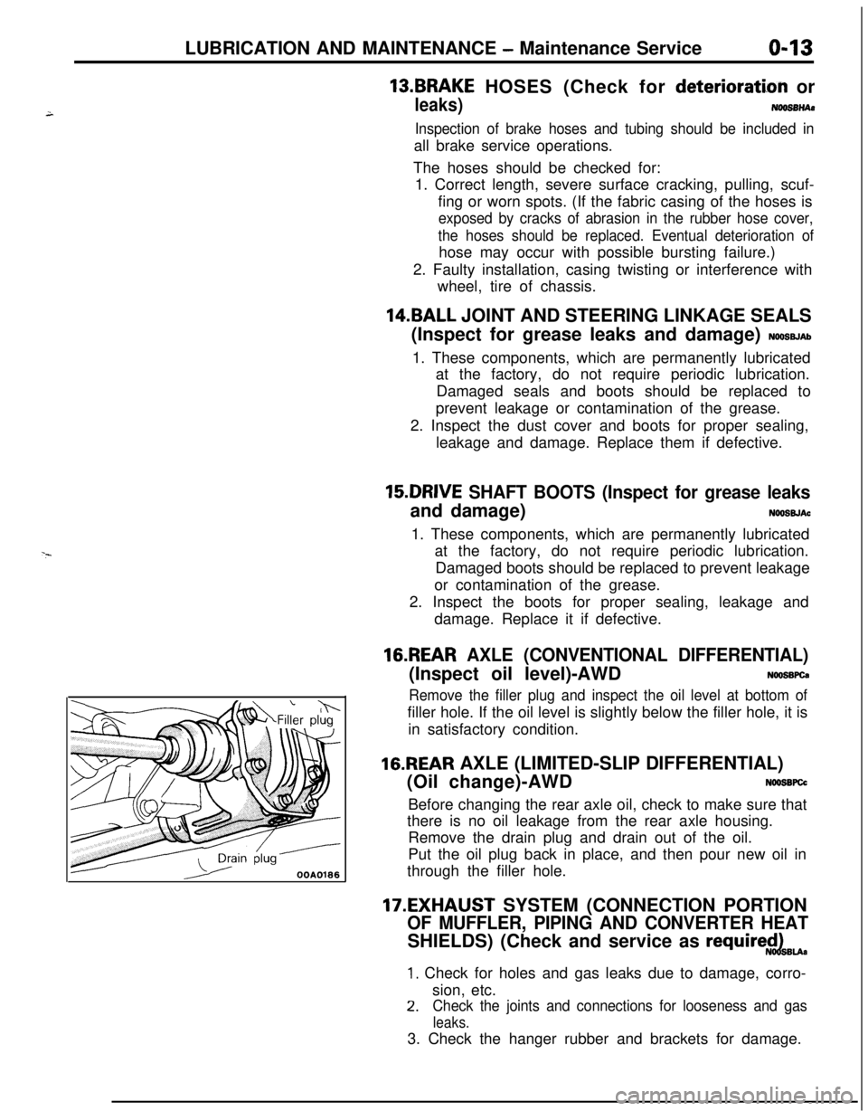
16.REAR AXLE (CONVENTIONAL DIFFERENTIAL)(Inspect oil level)-AWD
NWSBFCa
Remove the filler plug and inspect the oil level at bottom offiller hole. If the oil level is slightly below the filler hole, it is
in satisfactory condition.
16.REAR AXLE (LIMITED-SLIP DIFFERENTIAL)
(Oil change)-AWD
N66SBFCcBefore changing the rear axle oil, check to make sure that
there is no oil leakage from the rear axle housing.
Remove the drain plug and drain out of the oil.
Put the oil plug back in place, and then pour new oil in
through the filler hole.
17.EXHAUST SYSTEM (CONNECTION PORTION
OF MUFFLER, PIPING AND CONVERTER HEATSHIELDS) (Check and service as
require$dBu.
1. Check for holes and gas leaks due to damage, corro-
sion, etc.
2.Check the joints and connections for looseness and gas
leaks.3. Check the hanger rubber and brackets for damage.
Page 103 of 1216
3-1
REAR AXLE
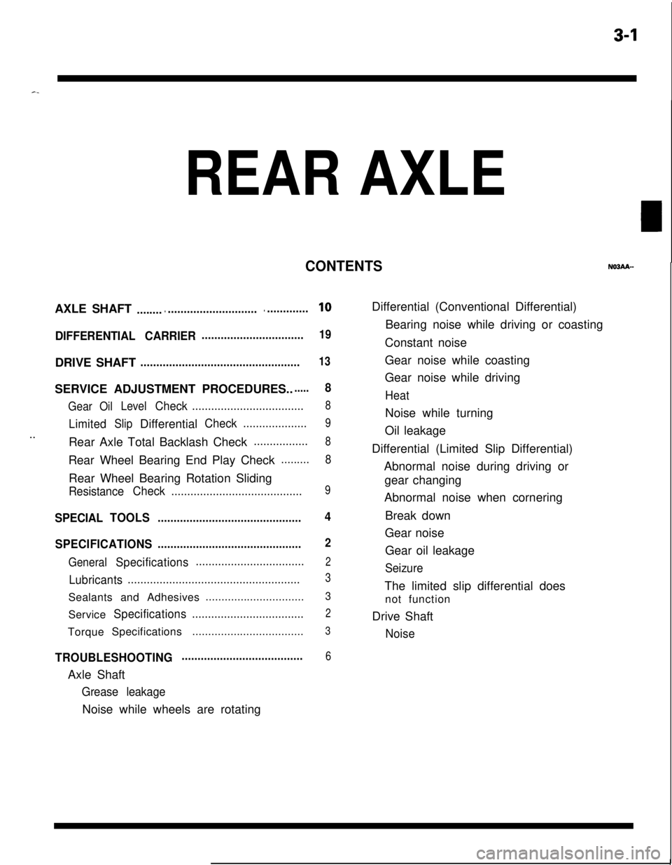
CONTENTSAXLE SHAFT
...................................................10
DIFFERENTIAL CARRIER................................19DRIVE SHAFT
..................................................13SERVICE ADJUSTMENT PROCEDURES..
.....8
GearOilLevelCheck...................................8
LimitedSlipDifferentialCheck....................9
..Rear Axle Total Backlash Check.................8Rear Wheel Bearing End Play Check
.........
8Rear Wheel Bearing Rotation Sliding
ResistanceCheck.........................................9
SPECIALTOOLS.............................................4
SPECIFICATIONS.............................................
2
GeneralSpecifications..................................2
Lubricants......................................................3Sealants and Adhesives...............................
3Service
Specifications...................................2TorqueSpecifications...................................
3
TROUBLESHOOTING......................................6Axle Shaft
Grease leakageNoise while wheels are rotatingDifferential (Conventional Differential)
Bearing noise while driving or coasting
Constant noise
Gear noise while coasting
Gear noise while driving
HeatNoise while turning
Oil leakage
Differential (Limited Slip Differential)
Abnormal noise during driving or
gear changing
Abnormal noise when cornering
Break down
Gear noise
Gear oil leakage
SeizureThe limited slip differential does
not function
Drive Shaft
Noise
Page 104 of 1216
3-2REAR AXLE - Specifications
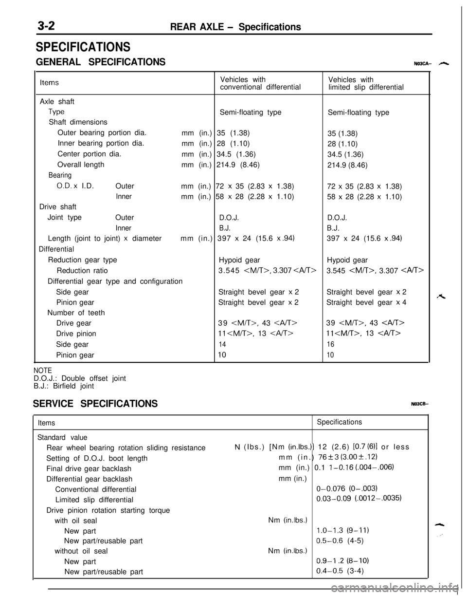
SPECIFICATIONS
GENERAL SPECIFICATIONSNO3CA- h
ItemsVehicles with
Vehicles with
conventional differential
limited slip differential
Axle shaft
TypeSemi-floating type
Semi-floating type
Shaft dimensions
Outer bearing portion dia.
mm (in.) 35 (1.38)
35 (1.38)
Inner bearing portion dia.
mm (in.) 28 (1.10)
28 (1.10)
Center portion dia.
mm (in.) 34.5 (1.36)
34.5 (1.36)
Overall length
mm (in.) 214.9 (8.46)
214.9 (8.46)
Bearing
O.D. x I.D.
Outer
mm (in.) 72 x 35 (2.83 x 1.38)
72 x 35 (2.83 x 1.38)
Innermm (in.) 58 x 28 (2.28 x 1.10)
58 x 28 (2.28 x 1.10)
Drive shaft
Joint type
Outer
D.O.J.D.O.J.
Inner
B.J.B.J.Length (joint to joint)
x diametermm (in.) 397 x 24 (15.6 x .94)397 x 24 (15.6 x .94)
DifferentialReduction gear type
Hypoid gearHypoid gear
Reduction ratio3.545
3.545
Side gearStraight bevel gear
x 2Straight bevel gear x 2
Pinion gearStraight bevel gear
x 2Straight bevel gear x 4
Number of teeth
Drive gear39
11
Side gear
1416Pinion gear
1010
NOTED.O.J.: Double offset joint
B.J.: Birfield joint
SERVICE SPECIFICATIONSNOBCB-
Items
Standard valueRear wheel bearing rotation sliding resistance
Setting of D.O.J. boot length
Final drive gear backlash
Differential gear backlash
Conventional differential
Limited slip differential
Drive pinion rotation starting torque
with oil seal
New part
New part/reusable part
without oil seal
New part
New part/reusable partSpecifications
N (Ibs.) [Nm (in.lbs.)l 12 (2.6) [0.7 (6)l or less
mm (in.)
76+3 (3.00+.12)
mm (in.) 0.1
l-0.16 (.004-,006)
mm (in.)O-0.076
(O-.003)
0.03-0.09 (.0012-.0035)
Nm
(in.lbs.)
1.0-1.3 (9-11)
0.5-0.6 (4-5)
Nm
(in.lbs.)
0.9-I .2 (8-10)
0.4-0.5 (3-4)
A
Page 105 of 1216
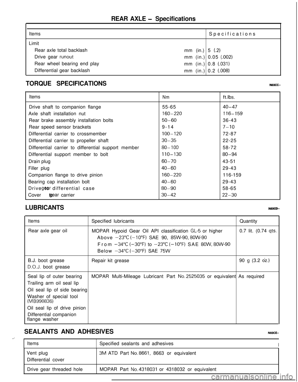
REAR AXLE - Specifications
ItemsLimit
Rear axle total backlash
Drive gear
runoutRear wheel bearing end play
Differential gear backlashSpecifications
mm (in.) 5
(.2)mm (in.) 0.05
(.002)mm (in.) 0.8
(.031)mm (in.) 0.2
(.008)
TORQUE SPECIFICATIONS
ItemsNmft.lbs.
Drive shaft to companion flange55-65
40-47Axle shaft installation nut
160-220116-159Rear brake assembly installation bolts
50-6036-43
Rear speed sensor brackets9-14
7-10Differential carrier to crossmember
100-12072-87
Differential carrier to propeller shaft
30-3522-25
Differential carrier to differential support
member80- 10058-72
Differential support member to bolt
110-13080-94Drain plug
60-7043-51
Filler plug40-6029-43
Companion flange to drive pinion
160-220116-159
Bearing cap installation bolt
40-6029-43
Drive to differential case
gear80-9058-65
Cover to carrier
gear30-4222-30
LUBRICANTS
ItemsRear axle gear oilSpecified lubricantsQuantity
MOPAR Hypoid Gear Oil API classification
GL-5 or higher0.7 lit. (0.74 qts.Above
-23°C (-10°F) SAE 90, 85W-90, 8OW-90From
-34°C (-30°F) to -23°C (-10°F) SAE 8OW, 8OW-90Below
-34°C (-30°F) SAE 75WB.J. boot grease
D.O.J. boot greaseRepair kit grease90
g (3.2 dz.)Seal lip of outer bearingMOPAR Multi-Mileage Lubricant Part No.2525035 or equivalent As required
Trailing arm oil seal lip
Oil seal lip of side bearing
Washer of special tool
(M B990836)Oil seal lip of drive pinion
Differential companion
flange washer
SEALANTS AND ADHESIVES
..-
ItemsSpecified sealants and adhesivesIVent plug
Differential cover3M ATD Part
No.8661, 8663 or equivalent
Drive gear threaded holeMOPAR Part
No.4318031 or 4318032 or equivalent
Page 106 of 1216

REAR AXLE - SDecial Tools
SPECIAL TOOLSN03DA--
ToolNumber
Name
UseMB990767
End yoke holderMeasurement of rotation torque of the limiter
/slip differentialStop axle shaft turning
CT-l 003Axle shaft pullerPress-fitting the drive pinion rear bearing outerace
Sliding hammer set
Removal of the axle shaftMB990560
Bearing removerRemoval of the axle shaft dust cover, oute
bearing and rear rotor
Press-in the outer wheel bearing and rear rotorMB991115
Oil seal installer
Press-fitting of drive shaft oil seal
Side bearing puller
Removal of the side
Page 108 of 1216
3-6REAR AXLE - Troubleshooting
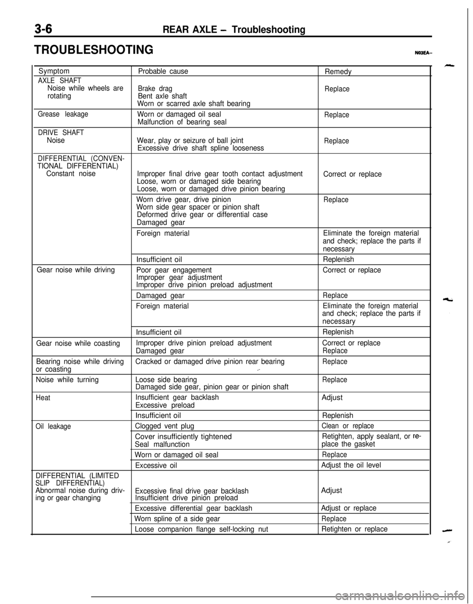
TROUBLESHOOTINGNO3EA-
Symptom
Probable cause
Remedy
AXLE SHAFTNoise while wheels areBrake drag
Replacerotating
Bent axle shaft
Worn or scarred axle shaft bearing
Grease leakageWorn or damaged oil sealReplaceMalfunction of bearing seal
DRIVE SHAFT
Noise
Wear, play or seizure of ball jointReplaceExcessive drive shaft spline looseness
DIFFERENTIAL (CONVEN-TIONAL DIFFERENTIAL)
Constant noise
Improper final drive gear tooth contact adjustment
Correct or replace
Loose, worn or damaged side bearing
Loose, worn or damaged drive pinion bearing
Worn drive gear, drive pinion
ReplaceWorn side gear spacer or pinion shaft
Deformed drive gear or differential case
Damaged gear
Foreign materialEliminate the foreign material
and check; replace the parts if
necessaryInsufficient oil
Replenish
Gear noise while driving
Poor gear engagementCorrect or replace
Improper gear adjustment
Improper drive pinion preload adjustment
Damaged gear
Replace
Foreign materialEliminate the foreign material
and check; replace the parts if
necessaryInsufficient oil
Replenish
Gear noise while coastingImproper drive pinion preload adjustmentCorrect or replace
Damaged gear
Replace
Bearing noise while drivingCracked or damaged drive pinion rear bearingReplace
or coasting.-
Noise while turningLoose side bearingReplaceDamaged side gear, pinion gear or pinion shaft
HeatInsufficient gear backlashAdjust
Excessive preloadInsufficient oil
Replenish
Oil leakageClogged vent plugClean or replaceCover insufficiently tightened
Retighten, apply sealant, or re-
Seal malfunctionplace the gasket
Worn or damaged oil seal
Replace
Excessive oilAdjust the oil level
DIFFERENTIAL (LIMITED
SLIP DIFFERENTIAL)Abnormal noise during driv-
Excessive final drive gear backlashAdjusting or gear changingInsufficient drive pinion preload
Excessive differential gear backlashAdjust or replace
Worn spline of a side gear
Replace
Loose companion flange self-locking nutRetighten or replace
Page 109 of 1216
REAR AXLE - Troubleshooting3-7
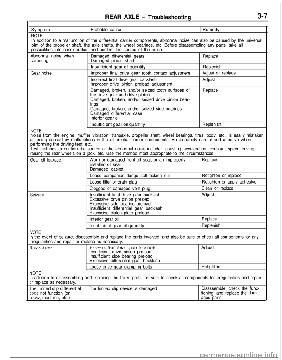
Symptom
NOTE
1 Probable cause1 Remedy
In addition to a malfunction of the differential carrier components, abnormal noise can also be caused by the universal
joint of the propeller shaft, the axle shafts, the wheel bearings, etc. Before disassembling any parts, take all
possibilities into consideration and confirm the source of the noise.
Abnormal noise when
Damaged differential gears
ReplacecorneringDamaged pinion shaftInsufficient gear oil quantity
Replenish
Gear noiseImproper final drive gear tooth contact adjustmentAdjust or replace
Incorrect final drive gear backlashAdjust
Improper drive pinion preload adjustment
Damaged, broken, and/or seized tooth surfaces of
Replacethe drive gear and drive pinion
Damaged, broken, and/or seized drive pinion bear-
ings
NOTE
Damaged, broken, and/or seized side bearings
Damaged differential case
Inferior gear oilInsufficient gear oil quantity
Replenish
Noise from the engine, muffler vibration, transaxle, propeller shaft, wheel bearings, tires, body, etc., is easily mistaken
as being caused by malfunctions in the differential carrier components. Be extremely careful and attentive whenperforming the driving test, etc.
Test methods to confirm the source of the abnormal noise include:coasting acceleration, constant speed driving,
raising the rear wheels on a jack, etc. Use the method most appropriate to the circumstances.
Gear oil leakageWorn or damaged front oil seal, or an improperlyReplace
installed oil seal
Damaged gasket
Seizure
VOTE
Loose companion flange self-locking nut
Loose filler or drain plug
Clogged or damaged vent plug
Insufficient final drive gear backlash
Excessive drive pinion preload
Excessive side bearing preload
Insufficient differential gear backlash
Excessive clutch plate preload
Inferior gear oilInsufficient gear oil quantityRetighten or replace
Retighten or apply adhesive
Clean or replaceAdjust
Replace
Replenish
n the event of seizure, disassemble and replace the parts involved, and also be sure to check all components for any
rregularities and repair or replace as necessary.
3reak downIncorrect final drive gear backlashAdjustInsufficient drive pinion preload
Insufficient side bearing preload
Excessive differential gear backlash
Loose drive gear clamping boltsRetighten
VOTEn addition to disassembling and replacing the failed parts, be sure to check all components for irregularities and repairIr
replace as necessary.
The limited slip differentialThe limited slip device is damagedDisassemble, check the func-
lees not function (ontioning, and replace the dam-
;now, mud, ice, etc.)aged parts
Page 110 of 1216
3-8REAR AXLE - Service Adjustment Procedures
09D031
llA0065SERVICE ADJUSTMENT PROCEDURES
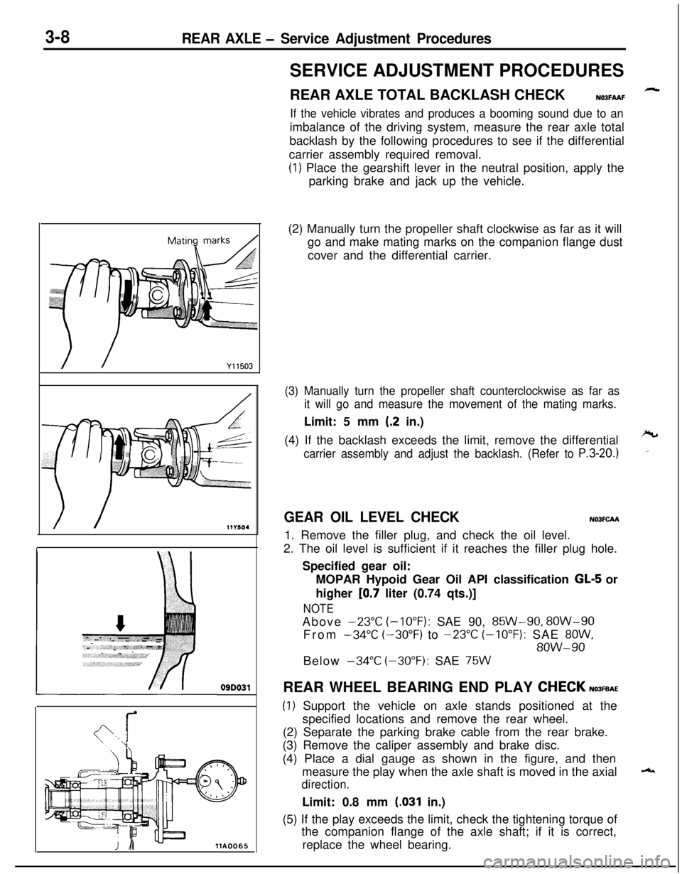
REAR AXLE TOTAL BACKLASH CHECK
N03FAAF
If the vehicle vibrates and produces a booming sound due to animbalance of the driving system, measure the rear axle total
backlash by the following procedures to see if the differential
carrier assembly required removal.
(1) Place the gearshift lever in the neutral position, apply the
parking brake and jack up the vehicle.
(2) Manually turn the propeller shaft clockwise as far as it will
go and make mating marks on the companion flange dust
cover and the differential carrier.
(3) Manually turn the propeller shaft counterclockwise as far as
it will go and measure the movement of the mating marks.Limit: 5 mm
(.2 in.)
(4) If the backlash exceeds the limit, remove the differential
carrier assembly and adjust the backlash. (Refer to P.3-20.)
GEAR OIL LEVEL CHECKN03FCAA1. Remove the filler plug, and check the oil level.
2. The oil level is sufficient if it reaches the filler plug hole.
Specified gear oil:
MOPAR Hypoid Gear Oil API classification
GL-5 or
higher
[0.7 liter (0.74 qts.)]
NOTEAbove
-23°C (-10°F): SAE 90, 85W-90, 8OW-90
From
-34°C (-30°F) to -23°C (-10°F): SAE 8OW,
8OW-90Below
-34°C (-30°F): SAE 75WREAR WHEEL BEARING END PLAY
CHECKN03FEAE
(1) Support the vehicle on axle stands positioned at the
specified locations and remove the rear wheel.
(2) Separate the parking brake cable from the rear brake.
(3) Remove the caliper assembly and brake disc.
(4) Place a dial gauge as shown in the figure, and then
measure the play when the axle shaft is moved in the axial
direction.Limit: 0.8 mm
(.031 in.)
(5) If the play exceeds the limit, check the tightening torque of
the companion flange of the axle shaft; if it is correct,
replace the wheel bearing.