service MITSUBISHI ECLIPSE 1991 Service Manual
[x] Cancel search | Manufacturer: MITSUBISHI, Model Year: 1991, Model line: ECLIPSE, Model: MITSUBISHI ECLIPSE 1991Pages: 1216, PDF Size: 67.42 MB
Page 1032 of 1216
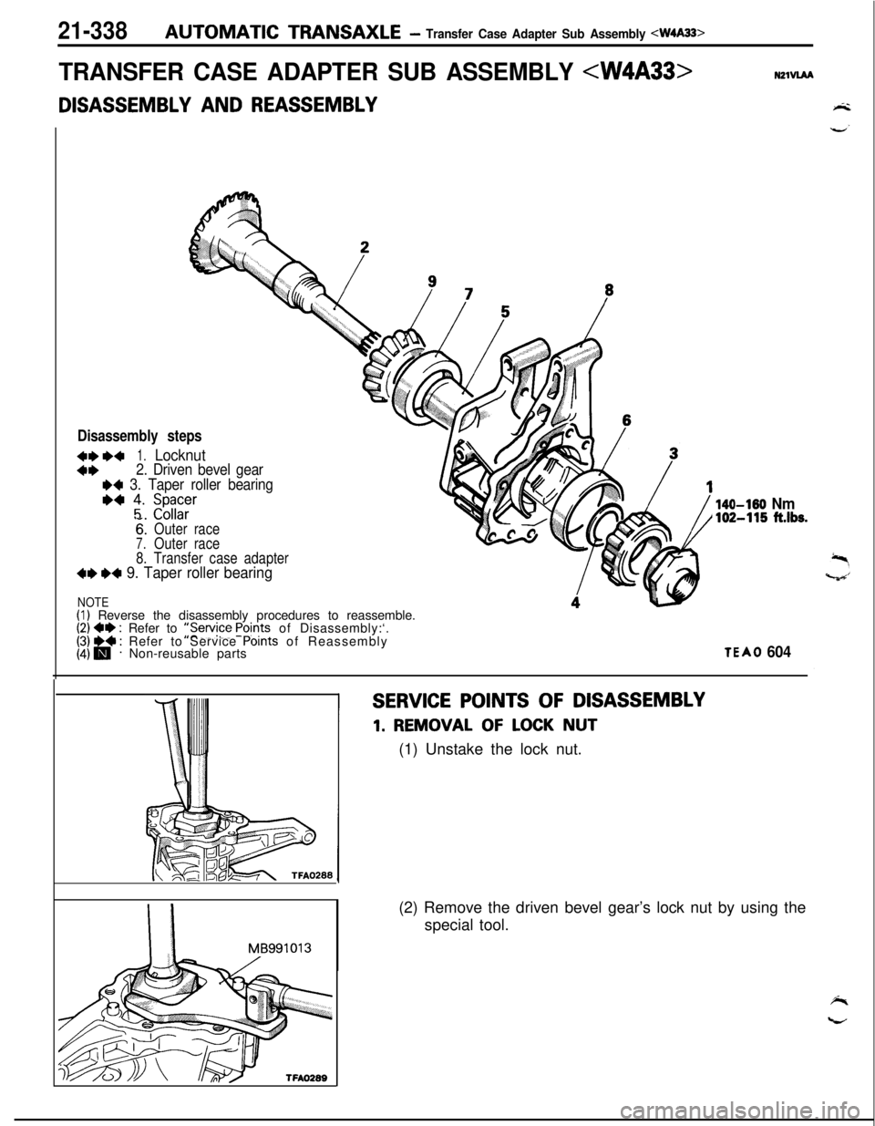
21-338AUTOMATIC TRANSAXLE- Transfer Case Adapter Sub Assembly 4W4A33>
TRANSFER CASE ADAPTER SUB ASSEMBLY
AND REASSEMBLY
Disassembly steps
4**+1.Locknut
4*2. Driven bevel gear
I)4 3. Taper roller bearing
*4 ;. ;z;;r
6:Outer race
7.Outer race
8. Transfer case adapter
4e W 9. Taper roller bearing
NOTE(I) Reverse the disassembly procedures to reassemble.(2) 4e : Refer to ::Service Points of Disassembly:‘.[j &@ j Refer to Service Points of Reassembly
Non-reusable parts
140-150 Nm102-115 ft.lbs.
TEA0 604
SERVICE POINTS OF DISASSEMBLY
1. REMOVAL OF LOCK NUT
(1) Unstake the lock nut.
I IMB991013
TFAO289(2) Remove the driven bevel gear’s lock nut by using the
special tool.
Page 1033 of 1216
AUTOMATIC TRANSAXLE - Transfer Case Adapter Sub Assembly
TFAO290
MD99881 2
MD99881 3
M D998825
I
MD99881 4
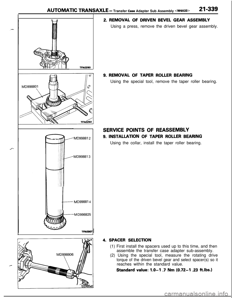
2. REMOVAL OF DRIVEN BEVEL GEAR ASSEMBLY
Using a press, remove the driven bevel gear assembly.
9. REMOVAL OF TAPER ROLLER BEARINGUsing the special tool, remove the taper roller bearing.
SERVICE POINTS OF REASSEMBLY
9. INSTALLATION OF TAPER ROLLER BEARINGUsing the collar, install the taper roller bearing.
4. SPACER SELECTION(1) First install the spacers used up to this time, and then
assemble the transfer case adapter sub-assembly.
(2) Using the special tool, measure the rotating drive
torque of the driven bevel gear and select spacer(s) so itreaches within the standard value.Standard
value: 1.0-l .7 Nm (0.72-I .23 ft.lbs.)
Page 1035 of 1216
AUTOMATIC TRANSAXLE- Transfer Case Sub Assembly
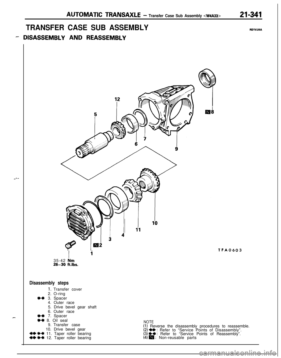
TRANSFER CASE SUB ASSEMBLY
- DISASSEMBLY AND REASSEMBLY
NZlVJAA
Ii35-42
irn26-30 ftlbs.
Disassembly steps
1.Transfer cover
2.O-ring
r)+3.Spacer4.Outer race
5. Drive bevel gear shaft
6.Outer race
**7.Spacer
I)+ 8. Oil seal9.Transfer case
10. Drive bevel gear
~~ e+ 11. Taper roller bearing~~ e+ 12. Taper roller bearing
TFA0603
NOTE(1) Reverse the disassembly procedures to reassemble.(2) +e : Refer to “Service Points of Disassembly”.(3) ~~ : Refer to “Service Points of Reassembly”.(4) m : Non-reusable parts
Page 1036 of 1216
21-342AUTOMATIC TRANSAXLE -Transfer Case Sub Assembly
MD99891 2\
MD998827.
MD998812
MD998818
TFA0302
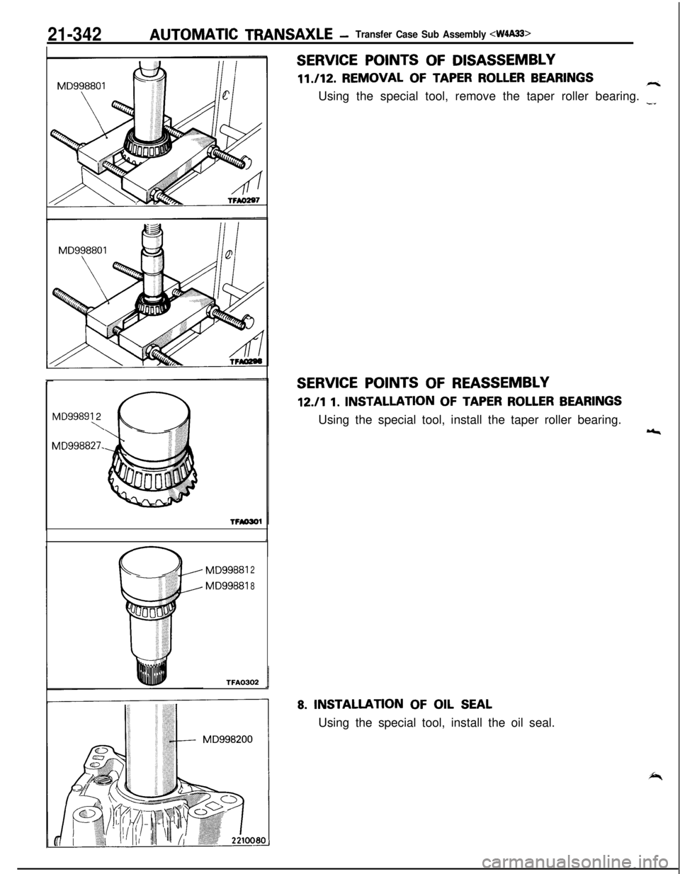
SERVICE POINTS OF DISASSEMBLY11./12. REMOVAL
OF TAPER ROLLER BEARINGSriUsing the special tool, remove the taper roller bearing.
-I
SERVICE POINTS OF REASSEMBLY
12./l 1. INSTALLATION OF TAPER ROLLER BEARINGSUsing the special tool, install the taper roller bearing.
r,
8. INSTALLATION OF OIL SEALUsing the special tool, install the oil seal.
Page 1039 of 1216
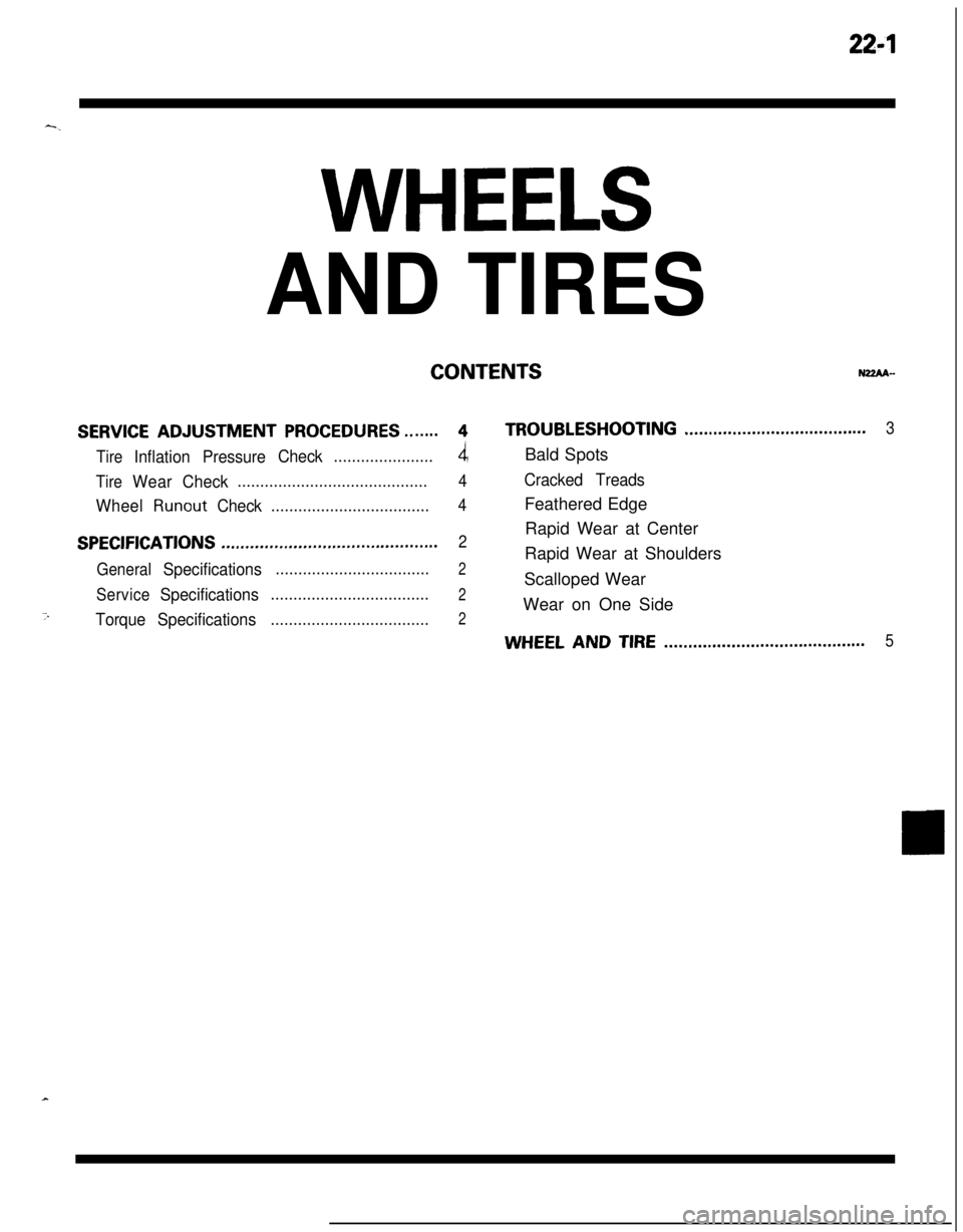
22-l-.
WHEELS
AND TIRES
CONTENTSNZZAA-
SERVICE ADJUSTMENT PROCEDURES.......4TROUBLESHOOTING......................................3
Tire
InflationPressureCheck......................4Bald Spots
TireWearCheck..........................................4Cracked Treads
Wheel
RunoutCheck...................................4Feathered Edge
SPECIFICATIONSRapid Wear at Center.............................................2
General
Specifications..................................2Rapid Wear at Shoulders
ServiceSpecificationsScalloped Wear...................................2Wear on One Side
7TorqueSpecifications...................................2
WHEEL AND TIRE..........................................5
Page 1040 of 1216
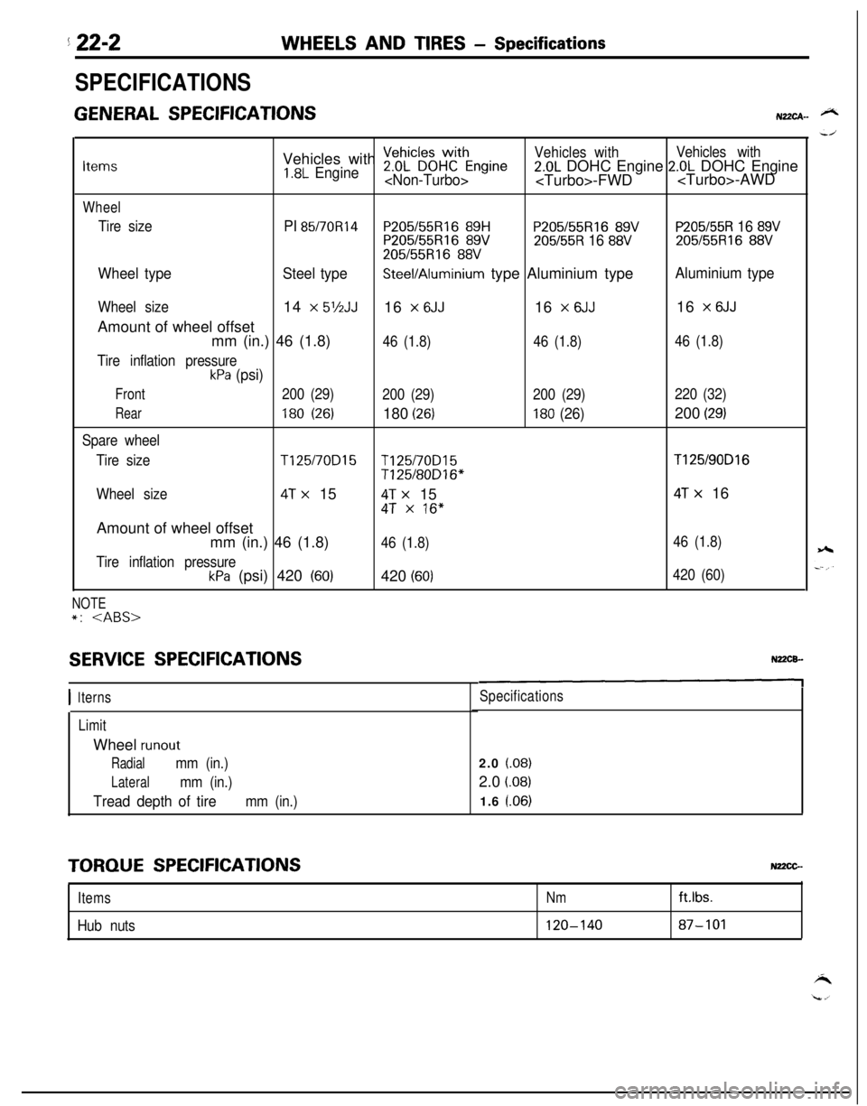
5 22-2WHEELS AND TIRES - Specifications
SPECIFICATIONS
GENERAL SPECIFICATIONSN22CA- @NVehicles with
~eDhL”~~HWCthEngineVehicles withVehicles withItems1.8L Engine2.0L DOHC Engine 2.0L DOHC Engine
Wheel
Tire sizePI 85/70R14P205155Rl6 89HP205/55R16 89VP205/55R 16 89VP205155R16 89V205/55R 16 88V205/55R16 88V
205/55R16 88V
Wheel typeSteel typeSteel/Aluminium type Aluminium typeAluminium type
Wheel size14 x 5’/2JJ16 x 6JJ16 x 6JJ16 x 6JJAmount of wheel offset
mm (in.) 46 (1.8)
46 (1.8)46 (1.8)46 (1.8)
Tire inflation pressure
kPa (psi)
Front200 (29)
200 (29)200 (29)220 (32)
Rear180 (26)180 (26)180 (26)200 (29)
Spare wheel
Tire size
T125/70D15T125/70D15T125/90D16
T125/80D16*
Wheel size
4T x 154T x 154T x 16
4T x 16”Amount of wheel offset
mm (in.) 46 (1.8)
46 (1.8)46 (1.8)
Tire inflation pressure
kPa (psi) 420 (60)420 (60)420 (60)
NOTE*:
SERVICE SPECIFICATIONS
I 1terns
LimitWheel
runout
Radialmm (in.)
Lateralmm (in.)
Tread depth of tiremm (in.)
Specifications2.0
(.08)2.0
i.08)1.6 l.06)
TORQUE SPECIFICATIONSNz2cG-
ItemsNm
Hub nuts120-140ftlbs.87-101
Page 1042 of 1216
22-4WHEELS AND TIRES - Service Adjustment Procedures
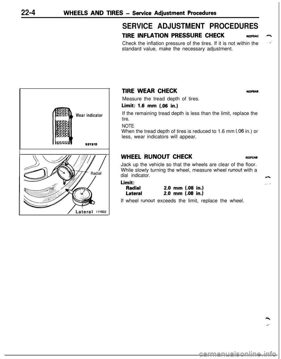
Wear indicator
53r510
/ Lateral 11Y602
SERVICE ADJUSTMENT PROCEDURES
TIRE INFLATION PRESSURE CHECKN2ZFOACCheck the inflation pressure of the tires. If it is not within the
standard value, make the necessary adjustment.
TIRE WEAR CHECKN2zFsABMeasure the tread depth of tires.Limit:
1.6 mm (.06 in,)If the remaining tread depth is less than the limit, replace the
tire.
NOTEWhen the tread depth of tires is reduced to 1.6 mm
(.06 in.) or
less, wear indicators will appear.
WHEEL RUNOUT CHECKNZ2FCA5Jack up the vehicle so that the wheels are clear of the floor.
While slowly turning the wheel, measure wheel
runout with a
dial indicator.Limit:
Radial2.0 mm (.08 in.)
Lateral2.0 mm (.08 in.)If wheel
runout exceeds the limit, replace the wheel.
Page 1043 of 1216
WHEELS AND TIRES - Wheel and Tire22-5
WHEEL AND TIRE
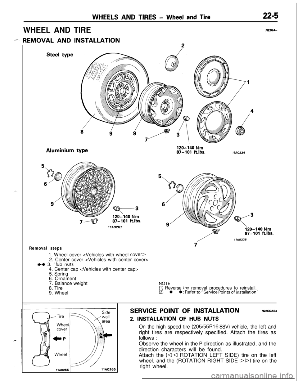
- REMOVAL AND INSTALLATIONSteel typeAluminium type
120-140 Nm87-101 ft.lbs.
1 lA0267
Removal steps
1. Wheel cover
I)+ 3. Hub nuts4. Center cap
5. Spring
6. Ornament
7. Balance weight
8. Tire
9. WheelNUGA-
120-140 Nm87-101 ftlbs.liA0334
o-140 Nm87-101 ft.lbs.
/llA0336
7
NOTE(1) Reverse the removal procedures to reinstall.(2) l 4 : Refer to “Service Points of Installation”
llAO2661 lAO265
SERVICE POINT OF INSTALLATIONNUGDABa
2. INSTALLATION OF HUB NUTS
On the high speed tire (205/55R16 88V) vehicle, the left andright tires are respectively specified. Attach the tires as
follows :Observe the wheel in the
P direction as illustrated, and the
direction characters will be found.
Attach the
(a Cl ROTATION LEFT SIDE) tire on the left
wheel, and the (ROTATION RIGHT SIDE
DD) tire on the
right wheel.
Page 1045 of 1216
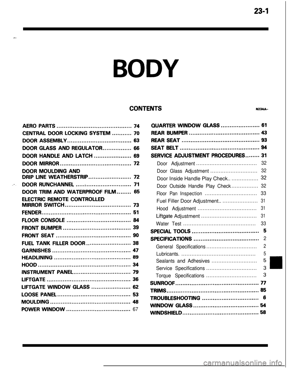
23-lBODY
CONTENTSN23Ak-
AERO PARTS..........................................74
CENTRAL DOOR LOCKING SYSTEM...........70
DOOR ASSEMBLY....................................63
DOOR GLASS AND REGULATOR................66
DOORHANDLEANDLATCH.....................69
DOOR MIRROR........................................72
DOOR MOULDING AND
DRIP LINE WEATHERSTRIP........................72
....DOOR RUNCHANNEL...............................71
DOOR TRIM AND WATERPROOF FILM........65
ELECTRIC REMOTE CONTROLLED
MIRROR SWITCH.....................................73
FENDER..................................................51
FLOOR CONSOLE....................................84
FRONT BUMPER......................................39
FRONT SEAT..........................................90
FUEL TANKFILLERDOOR.........................38
GARNISHES............................................47
HEADLINING...........................................89
HOOD....................................................34
INSTRUMENT PANEL................................79
LIFTGATE...............................................36
LIFTGATE WINDOWGLASS......................62
LOOSE PANEL.........................................53
MOULDING.............................................48
POWER WINDOW....................................67
QUARTERWINDOWGLASS......................61
REAR BUMPER........................................43
REAR SEAT............................................93
SEAT BELT.............................................94
SERVICE ADJUSTMENT PROCEDURES........31
Door Adjustment....................................32
Door Glass Adjustment............................32Door Inside Handle Play Check..................
32
Door Outside Handle Play Check................32
Floor PanInspection...............................
33Fuel Filler Door Adjustment.......................
31
Hood Adjustment...................................31
Liftgate Adjustment.................................31
Water Test...........................................33
SPECIAL TOOLS......................................5
SPECIFICATIONS.....................................2
General Specifications..............................
2
Lubricants.............................................5
Sealants and Adhesives...........................5
Service Specifications..............................3
Torque Specifications..............................3
SUNROOF...............................................77TRIMS
....................................................85
TROUBLESHOOTING................................6WINDOW
GLASS.....................................54
WINDSHIELD...........................................58
Page 1047 of 1216
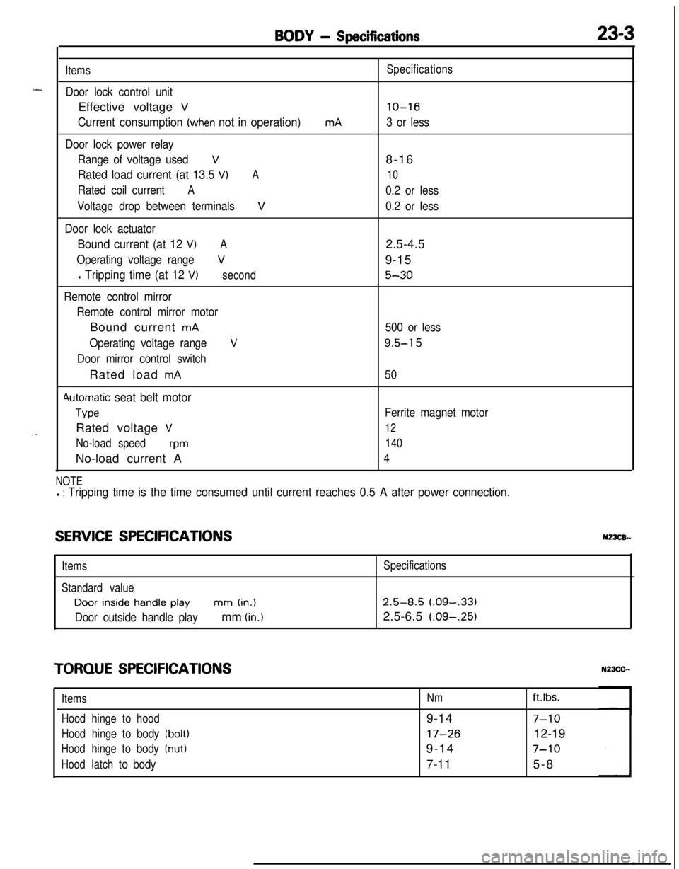
BODY - Specifications23-3
Items
Door lock control unitEffective voltage
V
Current consumption (when not in operation)
Door lock power relay
Range of voltage used
V
Rated load current (at 13.5 VIA
Rated coil currentA
Voltage drop between terminalsV
Door lock actuator
Bound current (at 12 VIA
Operating voltage rangeV
l Tripping time (at 12 V)second
Remote control mirror
Remote control mirror motorBound current
mA
Operating voltage range
V
Door mirror control switchRated load
mA
4utomatic seat belt motor
TypeRated voltage
V
No-load speedwmNo-load current A
mASpecifications
lo-16
3 or less8-16
10
0.2 or less
0.2 or less2.5-4.5
9-15
5-30
500 or less
9.5-l 5
50
Ferrite magnet motor
12
140
4
NOTEl : Tripping time is the time consumed until current reaches 0.5 A after power connection.
SERVICE SPECIFICATIONSN23CB--
ItemsSpecifications
Standard valueDoor
inside handle playmm (in.)2.5-8.5 (.09-,331
Door outside handle playmm (in.)2.5-6.5 (.09-.25)
TORQUE SPECIFICATIONS
ItemsNmft.lbs.
Hoodhingetohood9-14
7-10
Hoodhingetobody(bolt)17-2612-19
Hoodhingetobody(nut)9-147-10
Hoodlatchtobody7-115-8