differential MITSUBISHI ECLIPSE 1991 Owner's Manual
[x] Cancel search | Manufacturer: MITSUBISHI, Model Year: 1991, Model line: ECLIPSE, Model: MITSUBISHI ECLIPSE 1991Pages: 1216, PDF Size: 67.42 MB
Page 128 of 1216
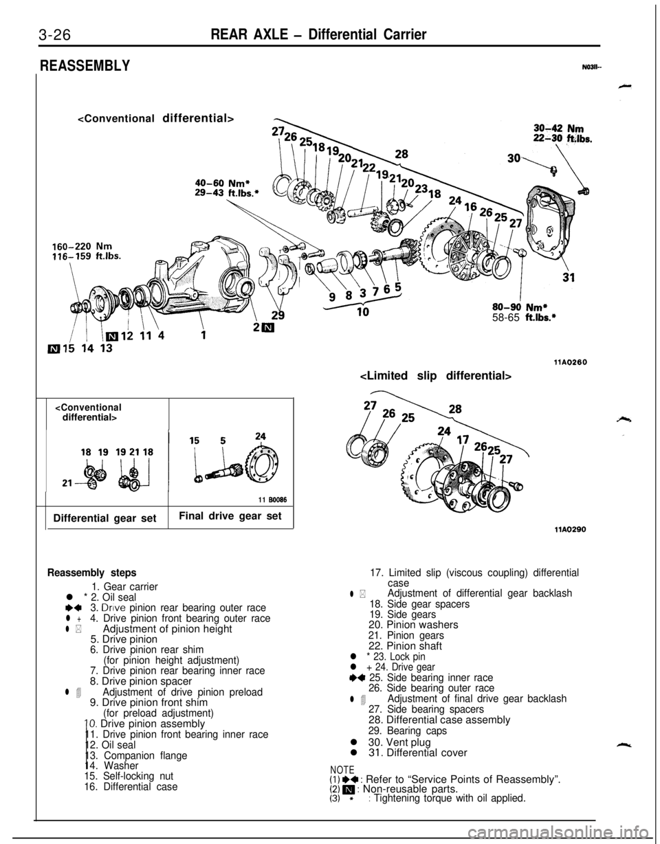
3-26REAR AXLE - Differential Carrier
REASSEMBLYN0311-
Nm*B-43 ft.lbs.*
80-90 Nm*58-65 ft.lbs.*
11 BOO86Differential gear setFinal drive gear set
Reassembly steps
1. Gear carrierl * 2. Oil seale+3. Drive pinion rear bearing outer racel +4. Drive pinion front bearing outer race
l *Adjustment of pinion height
5. Drive pinion
6. Drive pinion rear shim
(for pinion height adjustment)
7. Drive pinion rear bearing inner race8. Drive pinion spacer
l 4Adjustment of drive pinion preload9. Drive pinion front shim
(for preload adjustment)10. Drive pinion assembly11. Drive pinion front bearing inner race
12. Oil seal
13. Companion flange
14. Washer
15. Self-locking nut
16. Differential case
17. Limited slip (viscous coupling) differential
case
l *Adjustment of differential gear backlash
18. Side gear spacers
19. Side gears20. Pinion washers
21. Pinion gears22. Pinion shaft
l * 23. Lock pin
l + 24. Drive gear
+4 25. Side bearing inner race
26. Side bearing outer race
l 4Adjustment of final drive gear backlash
27. Side bearing spacers28. Differential case assembly
29. Bearing capsl 30. Vent plug
l
31. Differential cover
NOTE(I) I)+ : Refer to “Service Points of Reassembly”.[Z!/ m : Non-reusable parts.*: Tightening torque with oil applied.
Page 129 of 1216
REAR AXLE - Differential Carrier3-27
llK010
71
llY181llY182
.MB990836(MB990835)
llrm3
V223
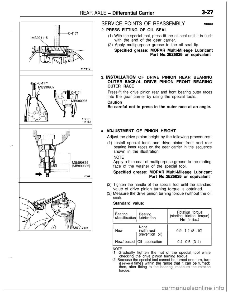
SERVICE POINTS OF REASSEMBLYNOJUBD2. PRESS FITTING OF OIL SEAL
(1) With the special tool, press fit the oil seal until it is flushwith the end of the gear carrier.
(2) Apply multipurpose grease to the oil seal lip.
Specified grease: MOPAR Multi-Mileage Lubricant
Part No.2525035 or equivalent
3. lNSTALLATlON OF DRIVE PINION REAR BEARING
OUTER RACE/4. DRIVE PINION FRONT BEARING
OUTER RACE
Press-fit the drive pinion rear and front bearing outer racesinto the gear carrier by using the special tools.
CautionBe careful not to press in the outer race at an angle.
l ADJUSTMENT OF PINION HEIGHT
Adjust the drive pinion height by the following procedures:
(1) Install special tools and drive pinion front and rear
bearing inner races on the gear carrier in the sequenceshown in the illustration.
NOTEApply a thin coat of multipurpose grease to the mating
face of the washer of the special tool.
Specified grease: MOPAR Multi-Mileage Lubricant
Part No.2525035 or equivalent
(2) Tighten the handle of the special tool until the standardvalue of drive pinion turning torque is obtained.
(3) Measure the drive pinion turning torque (without the oil
seal).Standard value:
Rotation torque
(starting friction torque)Nm
(in.lbs.)
I
NoneNew(with rust-I0.9-1.2 (8-10)prevention oil)New/reused Oil application
NOTE
0.4-0.5 (3-4)(I) Gradually tighten the nut of the special tool while
checking the drive pinion turning torque.
(2) Because the special tool cannot be turned one turn, turnit several times within the range that it can be turned;then, after fitting to the bearing, measure the rotation
torque.
Page 130 of 1216
3-28REAR AXLE - Differential Carrier
Y223
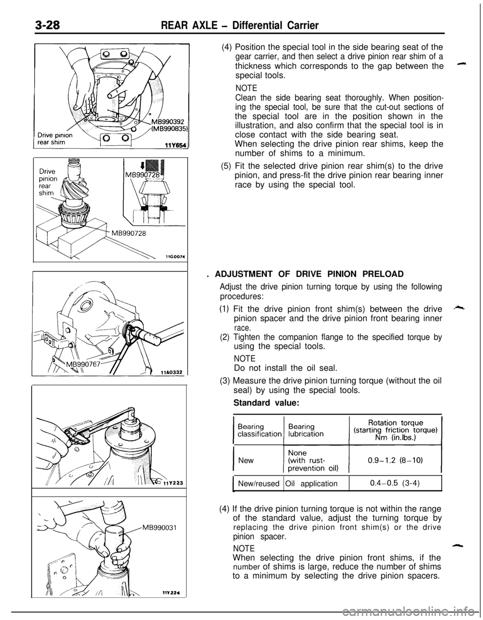
MB990031(4) Position the special tool in the side bearing seat of the
gear carrier, and then select a drive pinion rear shim of athickness which corresponds to the gap between the
special tools.
NOTE
Clean the side bearing seat thoroughly. When position-
ing the special tool, be sure that the cut-out sections ofthe special tool are in the position shown in the
illustration, and also confirm that the special tool is in
close contact with the side bearing seat.
When selecting the drive pinion rear shims, keep the
number of shims to a minimum.
(5) Fit the selected drive pinion rear shim(s) to the drive
pinion, and press-fit the drive pinion rear bearing inner
race by using the special tool.
. ADJUSTMENT OF DRIVE PINION PRELOAD
Adjust the drive pinion turning torque by using the following
procedures:
(1) Fit the drive pinion front shim(s) between the drive
pinion spacer and the drive pinion front bearing inner
race.
(2) Tighten the companion flange to the specified torque byusing the special tools.
NOTEDo not install the oil seal.
(3) Measure the drive pinion turning torque (without the oil
seal) by using the special tools.
Standard value:
21
.;c
1 New
New/reused Oil application
0.4-0.5 (3-4)
(4) If the drive pinion turning torque is not within the range
of the standard value, adjust the turning torque by
replacing the drive pinion front shim(s) or the drive
pinion spacer.
NOTEWhen selecting the drive pinion front shims, if the
number of shims is large, reduce the number of shims
to a minimum by selecting the drive pinion spacers.
Page 131 of 1216
REAR AXLE - Differential Carrier3-29
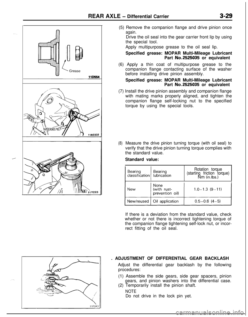
Y223(5) Remove the companion flange and drive pinion once
again.Drive the oil seal into the gear carrier front lip by using
the special tool.
Apply multipurpose grease to the oil seal lip.
Specified grease: MOPAR Multi-Mileage Lubricant
Part No.2525035 or equivalent
(6) Apply a thin coat of multipurpose grease to the
companion flange contacting surface of the washer
before installing drive pinion assembly.
Specified grease: MOPAR Multi-Mileage Lubricant
Part No.2525035 or equivalent
(7) Install the drive pinion assembly and companion flange
with mating marks properly aligned, and tighten the
companion flange self-locking nut to the specified
torque by using the special tools.
(8)Measure the drive pinion turning torque (with oil seal) toverify that the drive pinion turning torque complies with
the standard value.
Standard value:
Rotation torque
(starting friction torque)Nm
(in.lbs.)
IIIIIf there is a deviation from the standard value, check
whether or not there is incorrect tightening torque of
the companion flange tightening self-lock nut, or incor-
rect fitting of the oil seal.
. ADJUSTMENT OF DIFFERENTIAL GEAR BACKLASH
Adjust the differential gear backlash by the following
procedures:(1) Assemble the side gears, side gear spacers, pinion
gears, and pinion washers into the differential case.
(2) Temporarily install the pinion shaft.
NOTEDo not drive in the lock pin yet.
L-
Page 132 of 1216
REAR AXLE - Differential Carrier
I\I I!llGOO73I
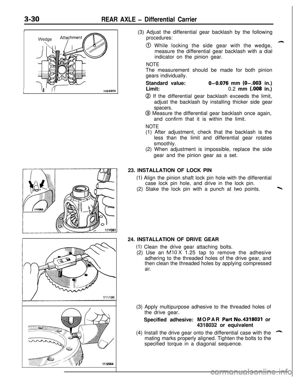
11 S564(3) Adjust the differential gear backlash by the following
procedures:
@ While locking the side gear with the wedge,
measure the differential gear backlash with a dial
indicator on the pinion gear.
NOTEThe measurement should be made for both pinion
gears individually.
Standard value:
O-0.076 mm (O-.003 in.)
Limit:0.2 mm
(.008 in.)
@ If the differential gear backlash exceeds the limit,
adjust the backlash by installing thicker side gear
spacers.
@ Measure the differential gear backlash once again,
and confirm that it is within the limit.
NOTE(1) After adjustment, check that the backlash is the
less than the limit and differential gear rotates
smoothly.
(2) When adjustment is impossible, replace the side
gear and the pinion gear as a set.
23. INSTALLATION OF LOCK PIN
(1) Align the pinion shaft lock pin hole with the differential
case lock pin hole, and drive in the lock pin.
(2) Stake the lock pin with a punch at two points.
w24. INSTALLATION OF DRIVE GEAR
(1) Clean the drive gear attaching bolts.
(2) Use an
Ml0 X 1.25 tap to remove the adhesive
adhering to the threaded holes of the drive gear, and
then clean the threaded holes by applying compressed
air.(3) Apply multipurpose adhesive to the threaded holes of
the drive gear.
Specified adhesive:MOPAR
Part No.4318031 or
4318032 or equivalent
(4) Install the drive gear onto the differential case with the
Amating marks properly aligned. Tighten the bolts to the
specified torque in a diagonal sequence.
Page 133 of 1216
REAR AXLE -Differential Carrier3-31
= Thicknessof the
spacer on one side
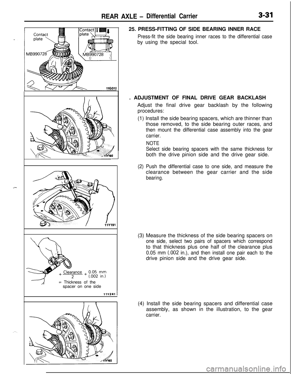
llV241I25. PRESS-FITTING OF SIDE BEARING INNER RACE
Press-fit the side bearing inner races to the differential caseby using the special tool.
. ADJUSTMENT OF FINAL DRIVE GEAR BACKLASH
Adjust the final drive gear backlash by the following
procedures:(1) Install the side bearing spacers, which are thinner than
those removed, to the side bearing outer races, and
then mount the differential case assembly into the gear
carrier.
NOTE
Select side bearing spacers with the same thickness forboth the drive pinion side and the drive gear side.
(2) Push the differential case to one side, and measure theclearance between the gear carrier and the side
bearing.(3) Measure the thickness of the side bearing spacers on
one side, select two pairs of spacers which correspondto that thickness plus one half of the clearance plus
0.05 mm (.002 in.), and then install one pair each to thedrive pinion side and the drive gear side.
(4) Install the side bearing spacers and differential case
assembly, as shown in the illustration, to the gear
carrier.
Page 134 of 1216
3-32REAR AXLE - Differential Carrier
llY167If backlash is too small
If backlash is too large
llY168
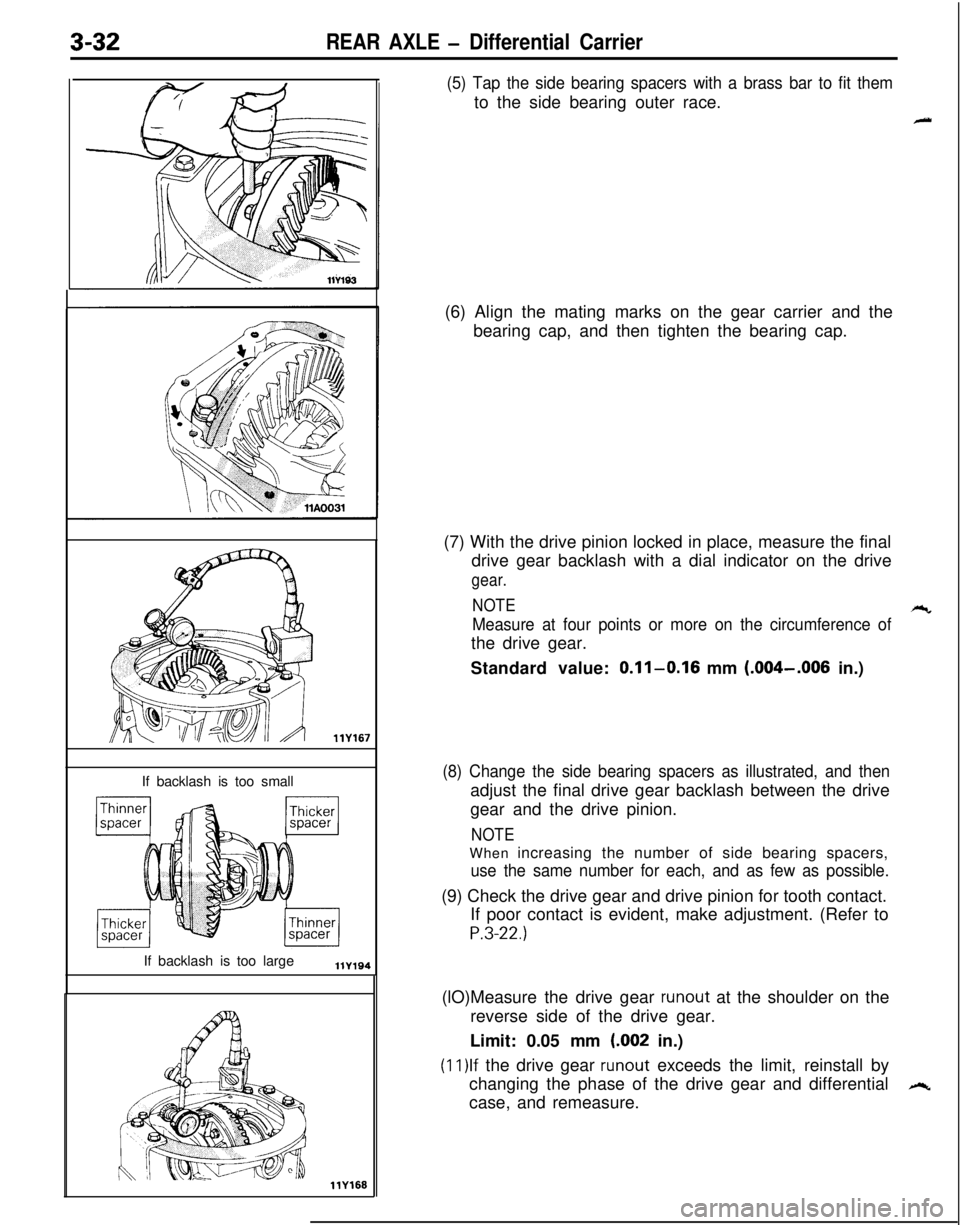
(5) Tap the side bearing spacers with a brass bar to fit themto the side bearing outer race.
4(6) Align the mating marks on the gear carrier and the
bearing cap, and then tighten the bearing cap.
(7) With the drive pinion locked in place, measure the final
drive gear backlash with a dial indicator on the drive
gear.
NOTE
-cc
Measure at four points or more on the circumference ofthe drive gear.
Standard value:
0.11-0.16 mm (.004-.006 in.)
(8) Change the side bearing spacers as illustrated, and thenadjust the final drive gear backlash between the drive
gear and the drive pinion.
NOTEWhen increasing the number of side bearing spacers,
use the same number for each, and as few as possible.(9) Check the drive gear and drive pinion for tooth contact.
If poor contact is evident, make adjustment. (Refer to
P.3-22.)(lO)Measure the drive gear
runout at the shoulder on the
reverse side of the drive gear.
Limit: 0.05 mm
(.002 in.)
(ll)lf the drive gear runout exceeds the limit, reinstall by
changing the phase of the drive gear and differential
,+case, and remeasure.
Page 135 of 1216
REAR AXLE - Differential Carrier3-3311
K60411K625
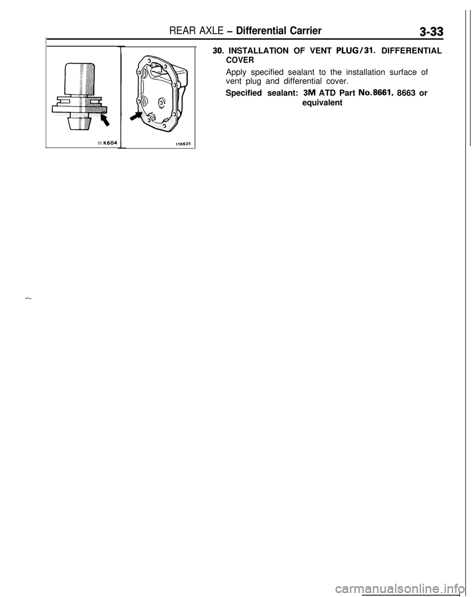
30. INSTALLATION OF VENT PLUG/31. DIFFERENTIAL
COVERApply specified sealant to the installation surface of
vent plug and differential cover.
Specified sealant: 3M ATD Part No.8661, 8663 or
equivalent
Page 136 of 1216
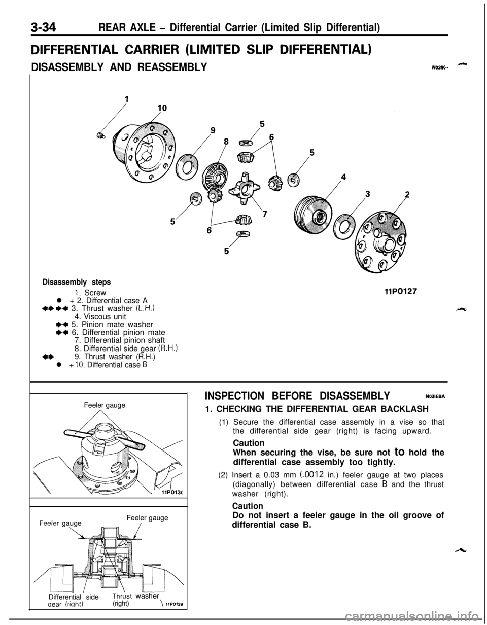
3-34REAR AXLE - Differential Carrier (Limited Slip Differential)
DIFFERENTIAL CARRIER (LIMITED SLIP DIFFERENTIAL)
DISASSEMBLY AND REASSEMBLYNO31K--
Disassembly steps
1. Screwl + 2. Differential case A+e I)+ 3. Thrust washer (L.H.)4. Viscous unit
llP0127
I)+ 5. Pinion mate washer
M 6. Differential pinion mate
7. Differential pinion shaft
8. Differential side gear
(R.H.)
4+9. Thrust washer (R.H.)
l +
10. Differential case 6Feeler gauge-eeler gauge
\Feeler gauge/
’ IL4l\’IIDifferential sideThrkt washer
aear (riaht)(right)\llPO139
INSPECTION BEFORE DISASSEMBLYNO3IEBA1. CHECKING THE DIFFERENTIAL GEAR BACKLASH
(1) Secure the differential case assembly in a vise so that
the differential side gear (right) is facing upward.
Caution
When securing the vise, be sure not to hold the
differential case assembly too tightly.
(2) Insert a 0.03 mm (.0012 in.) feeler gauge at two places
(diagonally) between differential case
B and the thrust
washer (right).
CautionDo not insert a feeler gauge in the oil groove of
differential case B.
Page 137 of 1216
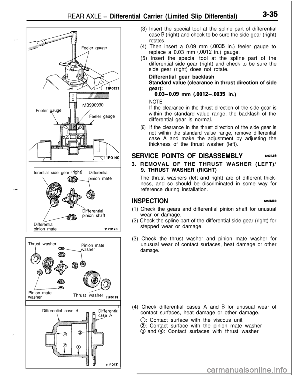
REAR AXLE - Differential Carrier (Limited Slip Differential)3-35ferential side gear
(right)Differential
Differential
pinion mate
llPO12BThrust washer
Pinion mate
Pinion mate
washerThrust washer
,,po,29Differential case
BerentiieA11
PO1311(3) Insert the special tool at the spline part of differential
case
B (right) and check to be sure the side gear (right)
rotates.(4) Then insert a 0.09 mm
(.0035 in.) feeler gauge to
replace a 0.03 mm (0012 in.) gauge.
(5) Insert the special tool at the spline part of the
differential side gear (right) and check to be sure the
side gear (right) does not rotate.
Differential gear backlash
Standard value (clearance in thrust direction of side
gear):
0.03-0.09 mm (.0012-.0035 in.)
NOTE
If the clearance in the thrust direction of the side gear iswithin the standard value range, the backlash of the
differential gear is normal.
(6)If the clearance in the thrust direction of the side gear is
not within the standard value range, remove differentialcase A and make the adjustment by adjusting the
thickness of the thrust washer (left).
SERVICE POINTS OF DISASSEMBLYNO3lLBB3. REMOVAL OF THE THRUST WASHER (LEFT)/
9. THRUST WASHER (RIGHT)
The thrust washers (left and right) are of different thick-
ness, and so should be discriminated in some way for
reference during installation.
INSPECTIONN03lMBB(1) Check the gears and differential pinion shaft for unusual
wear or damage.
(2) Check the spline part of the differential side gear (right) for
stepped wear or damage.
(3) Check the thrust washer and pinion mate washer for
unusual wear of contact surfaces, heat damage or other
damage.(4) Check differential cases A and
B for unusual wear of
contact surfaces, heat damage or other damage.
0: Contact surface with the viscous unit
0: Contact surface with the pinion mate washer
@ and @I: Contact surfaces with thrust washer