display MITSUBISHI ECLIPSE 1991 Service Manual
[x] Cancel search | Manufacturer: MITSUBISHI, Model Year: 1991, Model line: ECLIPSE, Model: MITSUBISHI ECLIPSE 1991Pages: 1216, PDF Size: 67.42 MB
Page 160 of 1216
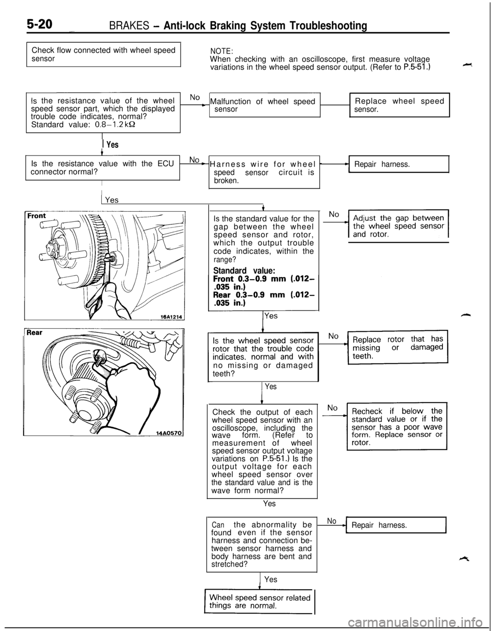
5-20 _BRAKES - Anti-lock Braking System TroubleshootingCheck flow connected with wheel speed
sensorNOTE:When checking with an oscilloscope, first measure voltage
variations in the wheel speed sensor output. (Refer to
P.5-51.)
Is the resistance value of the wheelNo c Malfunction of wheel speedReplace wheel speed
speed sensor part, which the displayedsensor
sensor.trouble code indicates, normal?
Standard value:
0.8-l .2 kQ
I YesIs the resistance value with the ECU
No c Harness wire for wheel -Repair harness.connector normal?
speed
sensorcircuit is
Ibroken.
II1
1
Is the standard value for the
gap between the wheel
speed sensor and rotor,
which the output trouble
code indicates, within the
range?
Standard value:
h
%Z~Pf!;!~~~e~no missing or damaged
teeth?
1 Yes
1Check the output of each
wheel speed sensor with an
oscilloscope, including the
waveform. (Refer to
measurement ofwheel
speed sensor output voltage
variations on
P.5-51 .I Is the
output voltage for each
wheel speed sensor over
the standard value and is thewave form normal?
Yes
Canthe abnormality beNoRepair harness.foundeven if the sensorIharness and connection be-
tween sensor harness and
body harness are bent and
estretched?
Yes
Page 162 of 1216
![MITSUBISHI ECLIPSE 1991 Service Manual 5-22BRAKES - Anti-lock Braking System Troubleshooting
1 E-4 1 Abnormality of solenoid valve drive circuit
[Explanation]
The ABS ECU normally monitors the solenoid valve
drive circuit.
If no current fl MITSUBISHI ECLIPSE 1991 Service Manual 5-22BRAKES - Anti-lock Braking System Troubleshooting
1 E-4 1 Abnormality of solenoid valve drive circuit
[Explanation]
The ABS ECU normally monitors the solenoid valve
drive circuit.
If no current fl](/img/19/57104/w960_57104-161.png)
5-22BRAKES - Anti-lock Braking System Troubleshooting
1 E-4 1 Abnormality of solenoid valve drive circuit
[Explanation]
The ABS ECU normally monitors the solenoid valve
drive circuit.
If no current flows in the solenoid even if the ECU
when turned OFF, the ECU determines the solenoidcoil wire is broken/short circuited or the harness
isbroken short circuited and then warning light lights
turns the solenoid ON or if it continues to flow even
up.
J/B
HU
(
x:OMBINATION ME
:TER
MA0603
Is the resistance value for
the solenoid valve, that the
displayed trouble code indi-cates, within the range of
the standard values?
Standard value: 3.0-3.2 Q
Is the solenoid valve resist-
ance value, that the output
trouble code displays, withinthe range of the standard
values when measured at
the ECU connector?
Standard value: 3.0-3.2 B
nOrmll/
Solenoid valve drive circuit is
NoReplace HU.I
NoThe harness wire for thesolenoid valvecircuit
whose resistance value is
outside the range of the
standard value is broken
or short circuited.
I
1 Repair ABS harness.
Page 175 of 1216
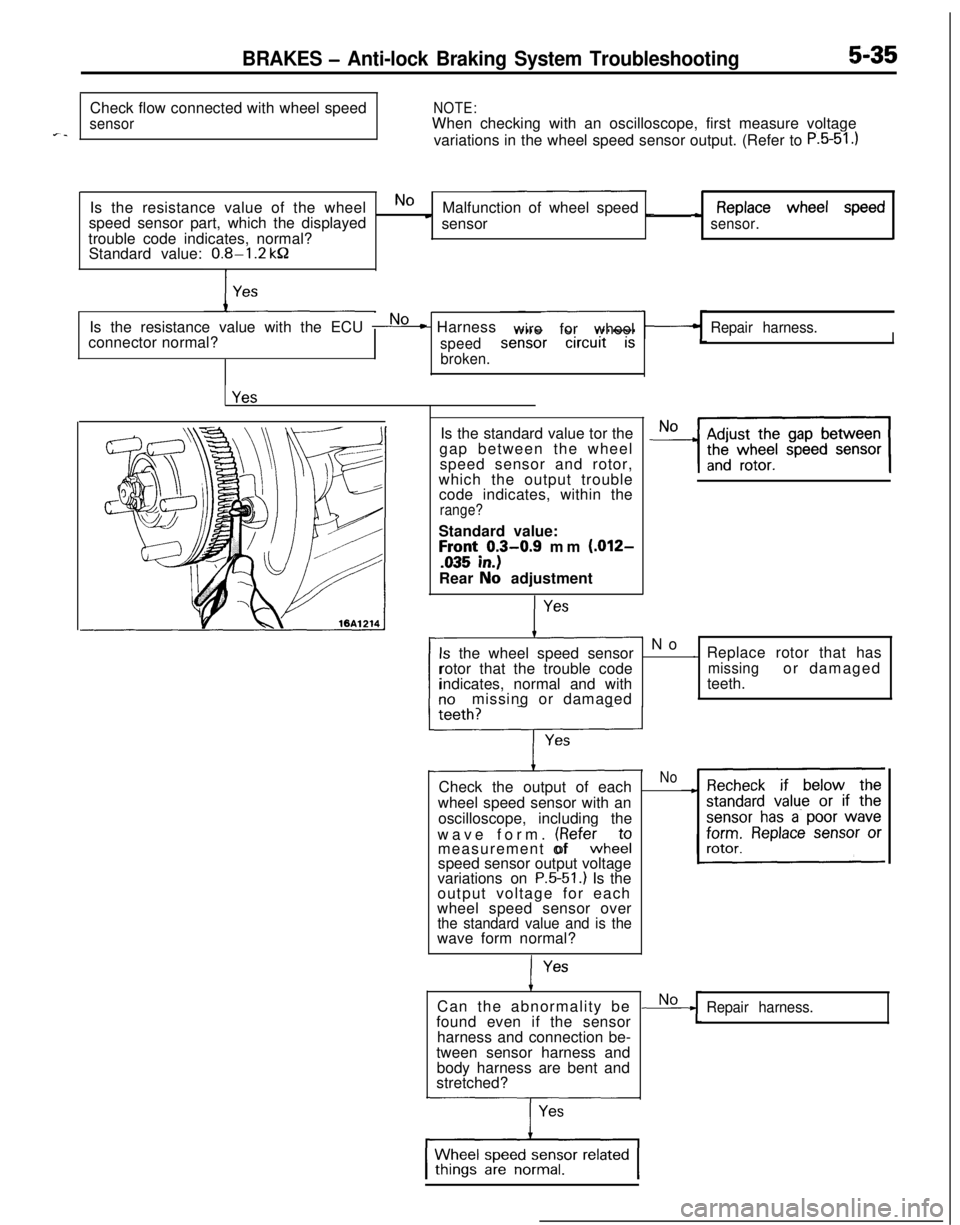
BRAKES - Anti-lock Braking System Troubleshooting5-35Check flow connected with wheel speed
NOTE:
sensorWhen checking with an oscilloscope, first measure voltagefl-variations in the wheel speed sensor output. (Refer to P.5-51.)Is the resistance value of the wheel
speed sensor part, which the displayed
No cMalfunction of wheel speed _~ Replacewheel speedsensor
sensor.trouble code indicates, normal?
Standard value:
0.8-l .2 kQIs the resistance value with the ECU
No* Harness
wireforwheelRepair harness.connector normal?
speedI
broken.Is the standard value tor the
gap between the wheel
speed sensor and rotor,
which the output trouble
code indicates, within the
range?Standard value:
h;ti;j3-0.9 mm (.012-Rear
Nb adjustment
- No
the wheel speed sensor. Replace rotor that has
rotor that the trouble code
missingor damaged
indicates, normal and withteeth.
missing or damaged
Check the output of each
wheel speed sensor with an
oscilloscope, including the
wave form.
(Refewhekqmeasurement of
speed sensor output voltage
variations on
P.5-51.) Is the
output voltage for each
wheel speed sensor over
the standard value and is thewave form normal?I
YesCan the abnormality be
found even if the sensor
harness and connection be-
tween sensor harness and
body harness are bent and
stretched?
No
Repair harness.
Page 575 of 1216

AUTO-CRUISE CONTROL SYSTEM - Troubleshooting'14421
16A065i
Auto-cruise
16LOOS
SELF-DIAGNOSIS CHECKSelf-diagnosis checking is performed when there has been an
automatic cancellation, without cancel switch
operati’on.(1) The following method can be used for checking the
diagnosis. Note that the diagnosis check connector is
located under the driver’s side instrument panel.
Connect a voltmeter between the ground terminal and the
terminal for auto-cruise control of the diagnosis check
connector.It is possible to discover which circuit is the cause of the
cancellation by verifying the indication shown by the
voltmeter with the display patterns shown on the next
page.(2) When the diagnosis code No. is displayed, inspect accord-
ing to the inspection chart No. related to each code No.
NOTECanceling the diagnosis codes
The diagnosis codes remain in memory until the battery is
turned off but they can be canceled in the following ways
without disconnecting the battery terminals.
1. By turning on the ignition switch
2.By turning the cruise switch ON while the SET switch is ONand then, within 1 second, turning the RESUME switch
ON. (Put into condition for input check reception)
3.By turning ON set SET switch and stop light switch at the
same time and continuing the ON condition for 5 seconds
or more.
4.By checking that the diagnosis codes are canceled using avoltmeter.
Page 576 of 1216
14-122AUTO-CRUISE CONTROL SYSTEM - Troubleshooting
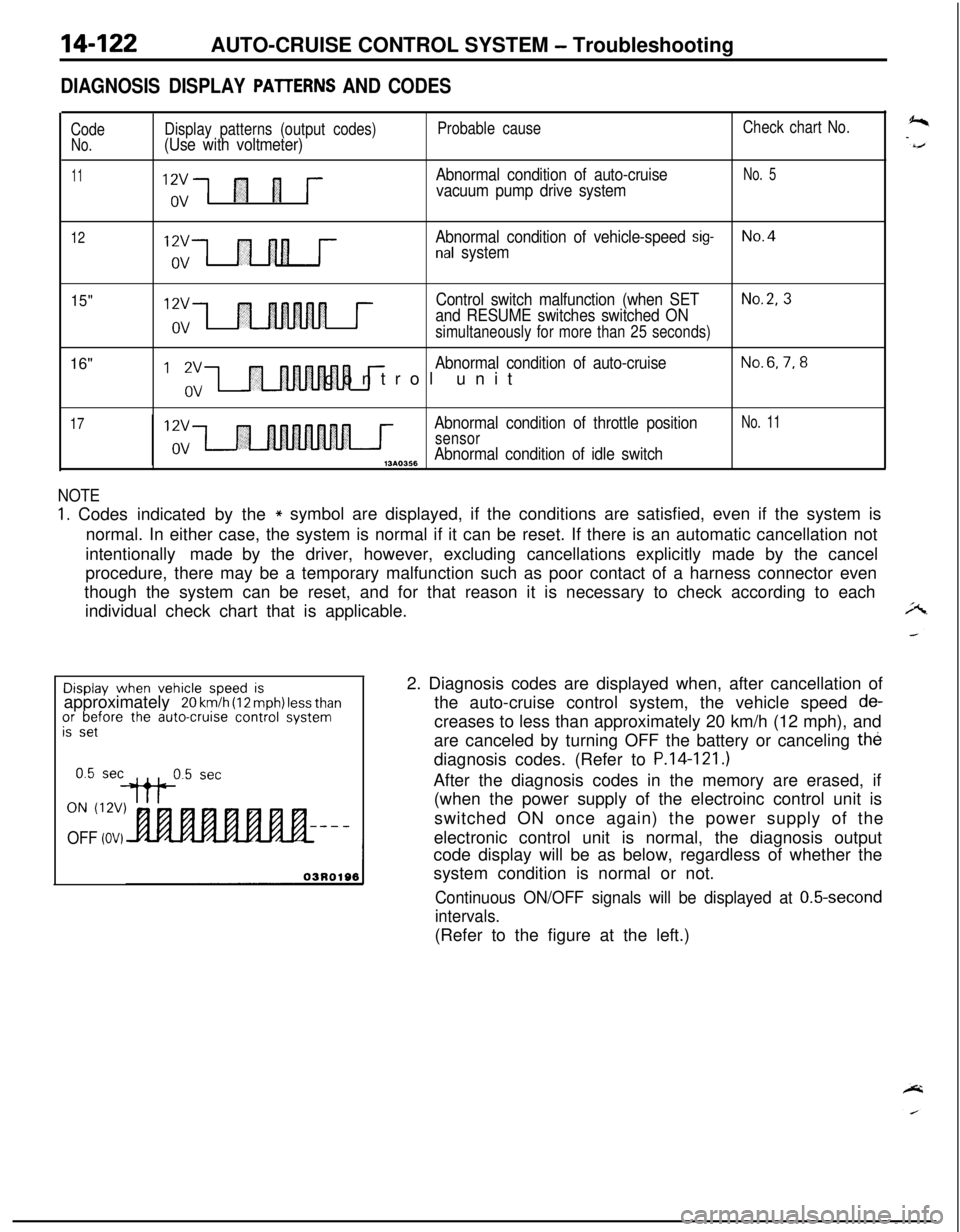
DIAGNOSIS DISPLAY PAlTERNS AND CODES
CodeNo.
11
Display patterns (output codes)(Use with voltmeter)
“,;1 fl 1 j--
Probable cause
Abnormal condition of auto-cruise
vacuum pump drive system
Check chart No.
No. 5
12Abnormal condition of vehicle-speed sig-No.4nal system
15"16"12vControl switch malfunction (when SETNo.2, 3
and RESUME switches switched ONovsimultaneously for more than 25 seconds)
I ‘,“,-I r
Abnormal condition of auto-cruiseNo.6,7,8control unit
17Abnormal condition of throttle positionNo. 11
sensorAbnormal condition of idle switch,3*0356
NOTE
1. Codes indicated by the* symbol are displayed, if the conditions are satisfied, even if the system is
normal. In either case, the system is normal if it can be reset. If there is an automatic cancellation not
intentionally made by the driver, however, excluding cancellations explicitly made by the cancel
procedure, there may be a temporary malfunction such as poor contact of a harness connector even
though the system can be reset, and for that reason it is necessary to check according to each
individual check chart that is applicable.Display
when vehicle speed isapproximately 20 km/h (12 mph) less thanor before the auto-cruise control systemis set
ON (12V)
OFF (OV)2. Diagnosis codes are displayed when, after cancellation of
the auto-cruise control system, the vehicle speed
de-creases to less than approximately 20 km/h (12 mph), and
are canceled by turning OFF the battery or canceling the
diagnosis codes. (Refer to
P.14-121.)After the diagnosis codes in the memory are erased, if
(when the power supply of the electroinc control unit is
switched ON once again) the power supply of the
electronic control unit is normal, the diagnosis output
code display will be as below, regardless of whether the
system condition is normal or not.
Continuous ON/OFF signals will be displayed at 0.5-second
intervals.(Refer to the figure at the left.)
Page 577 of 1216
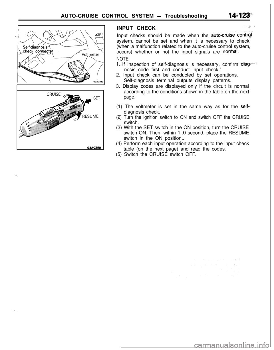
AUTO-CRUISE CONTROL SYSTEM - Troubleshooting14:f*L3’.INPUT CHECK
a *:;i’ _Input checks should be made when the
auto-cruise’.contr$system. cannot be set and when it is necessary to check.
(when a malfunction related to the auto-cruise control system,
occurs) whether or not the input signals are
no’rmal.
03A0258
NOTE
1. If inspection of self-diagnosis is necessary, confirm diag-nosis code first and conduct input check.’
2. Input check can be conducted by set operations.
Self-diagnosis terminal outputs display patterns.
3. Display codes are displayed only if the circuit is normal
according to the conditions shown in the table on the next
page.(1) The voltmeter is set in the same way as for the
self-diagnosis check.
(2) Turn the ignition switch to ON and switch OFF the CRUISEswitch.
(3) With the SET switch in the ON position, turn the CRUISE
switch ON. Then, within 1
.O second, place the RESUME
switch in the ON position..
(4) Perform each input operation according to the input check
table (on the next page) and read the codes.
(5) Switch the CRUISE switch OFF.
Page 578 of 1216
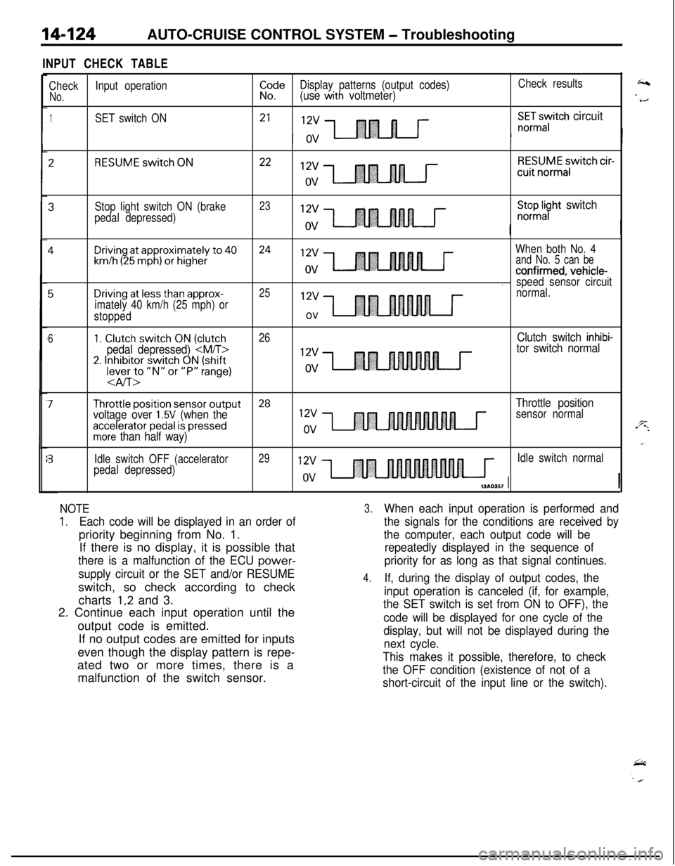
14-124AUTO-CRUISE CONTROL SYSTEM - Troubleshooting
INPUT CHECK TABLE
CheckInput operationiI!eDisplay patterns (output codes)Check results
No.(use with voltmeter)
1SET switch ON21X:Gayitch circuit
2RESUME switch ON2212vRESUME switch cir-cuit
normalov
3Stop light switch ON (brake23
pedal depressed)
;;pl;yht switch
4Driving at approximately to 4024When both No. 4
km/h (25 mph) or higherand No. 5 can be
co,nfirmed, vehicle-.speed sensor circuit
5Driving at less than approx-2512vnormal.
imately 40 km/h (25 mph) or
stopped
ov
61. Clutch switch ON (clutch26Clutch switch inhibi-
pedal depressed)
2. Inhibitor switch ON (shift12vlever to “N” or “P” range)ov
-aIT>
7Throttle position sensor output28
voltage over 1.5V (when theThrottle positionsensor normal
accelerator pedal is pressedmore than half way)
?Idle switch OFF (accelerator29Idle switch normal
pedal depressed)
NOTE
1.Each code will be displayed in an order ofpriority beginning from No. 1.
If there is no display, it is possible that
there is a malfunction of the ECU power-
supply circuit or the SET and/or RESUMEswitch, so check according to check
charts
1,2 and 3.
2. Continue each input operation until the
output code is emitted.
If no output codes are emitted for inputs
even though the display pattern is repe-
ated two or more times, there is a
malfunction of the switch sensor.
3.When each input operation is performed and
the signals for the conditions are received by
the computer, each output code will be
repeatedly displayed in the sequence of
priority for as long as that signal continues.
4.If, during the display of output codes, the
input operation is canceled (if, for example,
the SET switch is set from ON to OFF), the
code will be displayed for one cycle of the
display, but will not be displayed during the
next cycle.
This makes it possible, therefore, to check
the OFF condition (existence of not of a
short-circuit of the input line or the switch).