jack points MITSUBISHI ECLIPSE 1991 Service Manual
[x] Cancel search | Manufacturer: MITSUBISHI, Model Year: 1991, Model line: ECLIPSE, Model: MITSUBISHI ECLIPSE 1991Pages: 1216, PDF Size: 67.42 MB
Page 77 of 1216
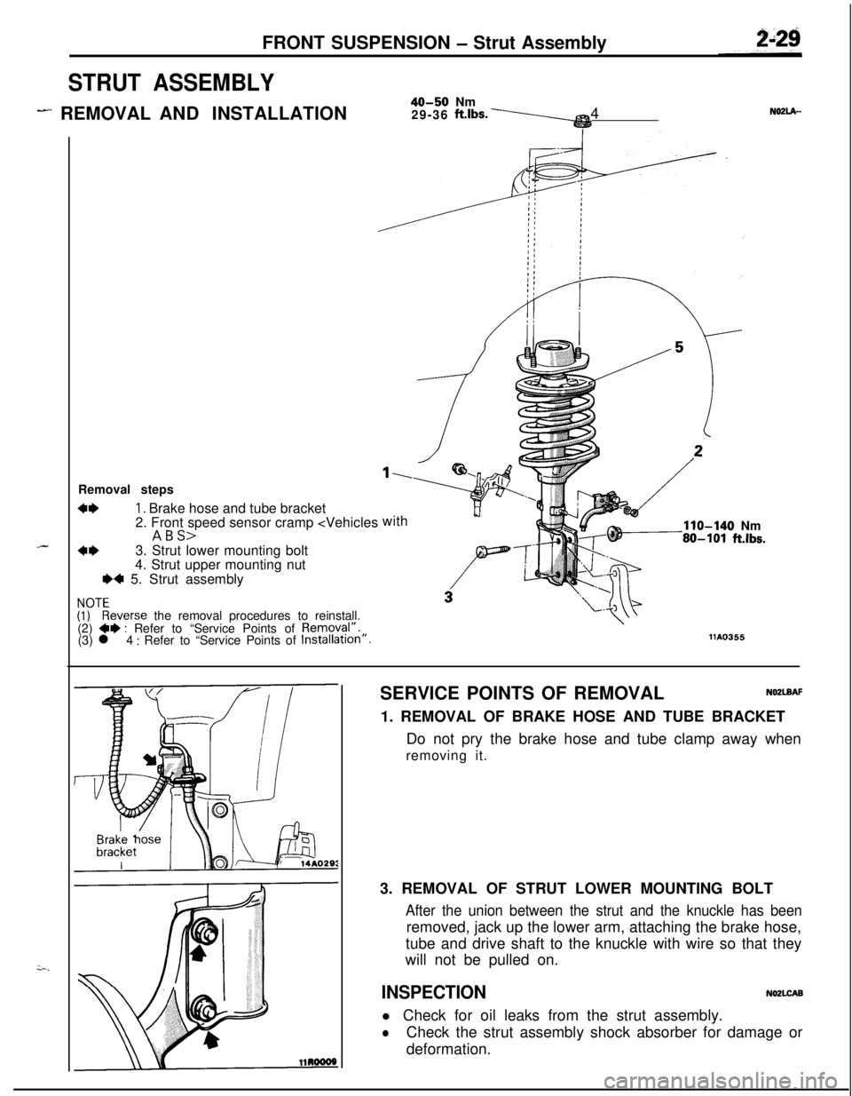
FRONT SUSPENSION - Strut Assembly
STRUT ASSEMBLY
- REMOVAL AND INSTALLATION40-50 Nm
29-36 ft.lbs.\4N02lA-
.-Removal steps
4*1. Brake hose and tube bracket
2. Front speed sensor cramp
4*3. Strut lower mounting bolt
4. Strut upper mounting nut
e+ 5. Strut assembly
!rEeverse the removal procedures to reinstall.
(2) **: Refer to “Service Points of Removal”.
(3) l 4 : Refer to “Service Points of Installation”.
1.with
110-140 Nm80-101 ft.lbs.
1110355SERVICE POINTS OF REMOVAL
NO2LBAF1. REMOVAL OF BRAKE HOSE AND TUBE BRACKET
Do not pry the brake hose and tube clamp away when
removing it.
3. REMOVAL OF STRUT LOWER MOUNTING BOLT
After the union between the strut and the knuckle has beenremoved, jack up the lower arm, attaching the brake hose,
tube and drive shaft to the knuckle with wire so that they
will not be pulled on.
INSPECTIONNO2LCABl Check for oil leaks from the strut assembly.
lCheck the strut assembly shock absorber for damage or
deformation.
Page 191 of 1216
![MITSUBISHI ECLIPSE 1991 Service Manual BRAKES - Service Adjustment Procedures5-51E.C.U. terminal
ILow gear idle condition
[Speed: 5-6 km (3.1-3.16
mph)]Approx.
5V
14A0580When increasing speed
[Speed:
15-20 km (9.3-12.4 mph11OBSERVATION MITSUBISHI ECLIPSE 1991 Service Manual BRAKES - Service Adjustment Procedures5-51E.C.U. terminal
ILow gear idle condition
[Speed: 5-6 km (3.1-3.16
mph)]Approx.
5V
14A0580When increasing speed
[Speed:
15-20 km (9.3-12.4 mph11OBSERVATION](/img/19/57104/w960_57104-190.png)
BRAKES - Service Adjustment Procedures5-51E.C.U. terminal
ILow gear idle condition
[Speed: 5-6 km (3.1-3.16
mph)]Approx.
5V
14A0580When increasing speed
[Speed:
15-20 km (9.3-12.4 mph11OBSERVATION OF WHEEL SPEED SENSOR
OUTPUT VOLTAGE VARIATIONS
(1) Jack up the vehicle and release the parking brake.
(2) Disconnect the electronic control unit harness connector,
and measure the speed sensor output voltage at the
vehicle side harness connector.
(3) With an AWD model, put the shift lever in
1st (MTT) or L(A/T) position, rotate the wheels and observe the wave
shape for each wheel. With an FWD model, put the shift
lever in
1st (M/T) or L (AiT) position, rotate the wheels and
observe the wave shape for the front wheels; for the rear
wheels, rotate the wheels by hand and monitor the wave
shape.
NOTEIt is also
allright to actually drive the car.
ISpeed sensor
E.C.U. terminal No.I
IFront leftI14-15I
IFront right31-33I
IRear right28-30I
IRear left1 10-11IWhen wheel speed is slow, the output voltage is low
and it gets higher as the speed increases.
Wave shape monitoring points
IS THE OUTPUTVOLTAGE (AMPLITUDE) TOO LOW OR ISTHERE NO OUTPUT VOLTAGE?
If it is too low, check each wheel speed sensor,
With FWD rear wheels, check the sensor gap.
IS THERE VARIATION IN THE WAVE SHAPE AMPLITUDE?
If the flicker of the amplitude is large, consider shaking
of the axle hub.
IS THERE NOISE IN THE WAVE SHAPE OR DISTORTION?Broken or disconnected wire due to vibration or
installation malfunction of the wheel speed sensor.
Check rotor teeth meshing, breaks, etc.
Approx. 1 OV
14A0501
Page 267 of 1216
COOLING - Water Pump <1.8L Engine>749SERVICE POINTS OF REMOVAL
NO’IMCAG
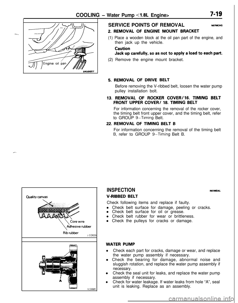
2. REMOVAL OF ENGINE MOUNT BRACKET
(1) Place a wooden block at the oil pan part of the engine, andthen jack up the vehicle.
Caution
Jack up carefully, so as not to apply a load to each part.(2) Remove the engine mount bracket.
\
\
Core wireAdhesive
rubber
Rib rubber1 coo21
5. REMOVAL OF DRIVE BELTBefore removing the V-ribbed belt, loosen the water pump
pulley installation bolt.
13. REMOVAL OF ROCKER COVER/16. TIMING BELT
FRONT UPPER COVER/ 18. TIMING BELT
For information concerning the removal of the rocker cover,the timing belt front upper cover, and the timing belt, refer
to GROUP
g-Timing Belt.
22. REMOVAL OF TIMING BELT BFor information concerning the removal of the timing belt
B, refer to GROUP g-Timing Belt B.
INSPECTIONN07MDAL
V-RIBBED BELTCheck following items and replace if faulty.
l Check belt surface for damage, peeling or cracks.
l Check belt surface for oil or grease.
l Check belt rubber for wear or brittleness.
l Check the pulleys for cracks or damage.
WATER PUMP
lCheck each part for cracks, damage or wear, and replace
the water pump assembly if necessary.
l Check the bearing for damage, abnormal noise and
sluggish rotation, and replace the water pump assembly if
necessary.lCheck the seal unit for leaks, and replace the water pump
assembly if necessary.
lCheck for water leakage. If water leaks from hole “A”, seal
unit is leaking. Replace as an assembly.
Page 270 of 1216
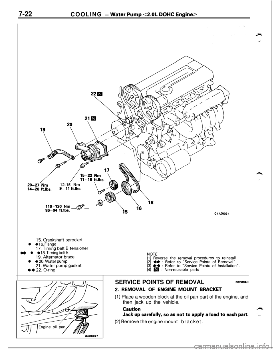
7-22COOLING - Water Pump <2.0L DOHC Engine>
20-27-Nm12-15 Nm14-20 ft.lbs.9- 11 ftlbs.\,/”
110-130 Nm@80-94 ftlbs. -04A0094
15. Crankshaft sprocketl a 16. Flange17. Timing belt B tensioner4e l + 18. Timing belt B19. Alternator bracel 4 20. Water pump21. Water pump gasketI)* 22. O-ring
NOTE(I) Reverse the removal procedures to reinstall.(2) 4* : Refer to “Service Points of Removal”.(3) ** : Refer to “Service Points of Installation”.(4) m : Non-reusable partsSERVICE POINTS OF REMOVAL
NO’IMCAH
2. REMOVAL OF ENGINE MOUNT BRACKET
(1) Place a wooden block at the oil pan part of the engine, and
then jack up the vehicle.
Cautioncylb
Jack up carefully, so as not to apply a load to each part..__
(2) Remove the engine mount bracket.
Page 322 of 1216
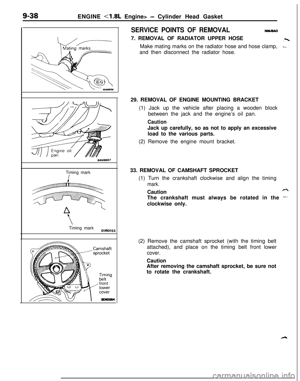
9-38ENGINE <1.8L Engine> - Cylinder Head Gasket
04UOO27Timing mark
\Timing mark
OlR0153
SERVICE POINTS OF REMOVALNWJSAO7. REMOVAL OF RADIATOR UPPER HOSE
,zMake mating marks on the radiator hose and hose clamp,
b-and then disconnect the radiator hose.
29. REMOVAL OF ENGINE MOUNTING BRACKET
(1) Jack up the vehicle after placing a wooden block
between the jack and the engine’s oil pan.
CautionJack up carefully, so as not to apply an excessive
load to the various parts.
(2) Remove the engine mount bracket.
33. REMOVAL OF CAMSHAFT SPROCKET
(1) Turn the crankshaft clockwise and align the timing
mark.Caution
rzThe crankshaft must always be rotated in the
-’clockwise only.
(2) Remove the camshaft sprocket (with the timing belt
attached), and place on the timing belt front lower
cover.Caution
After removing the camshaft sprocket, be sure not
to rotate the crankshaft.
R
Page 326 of 1216
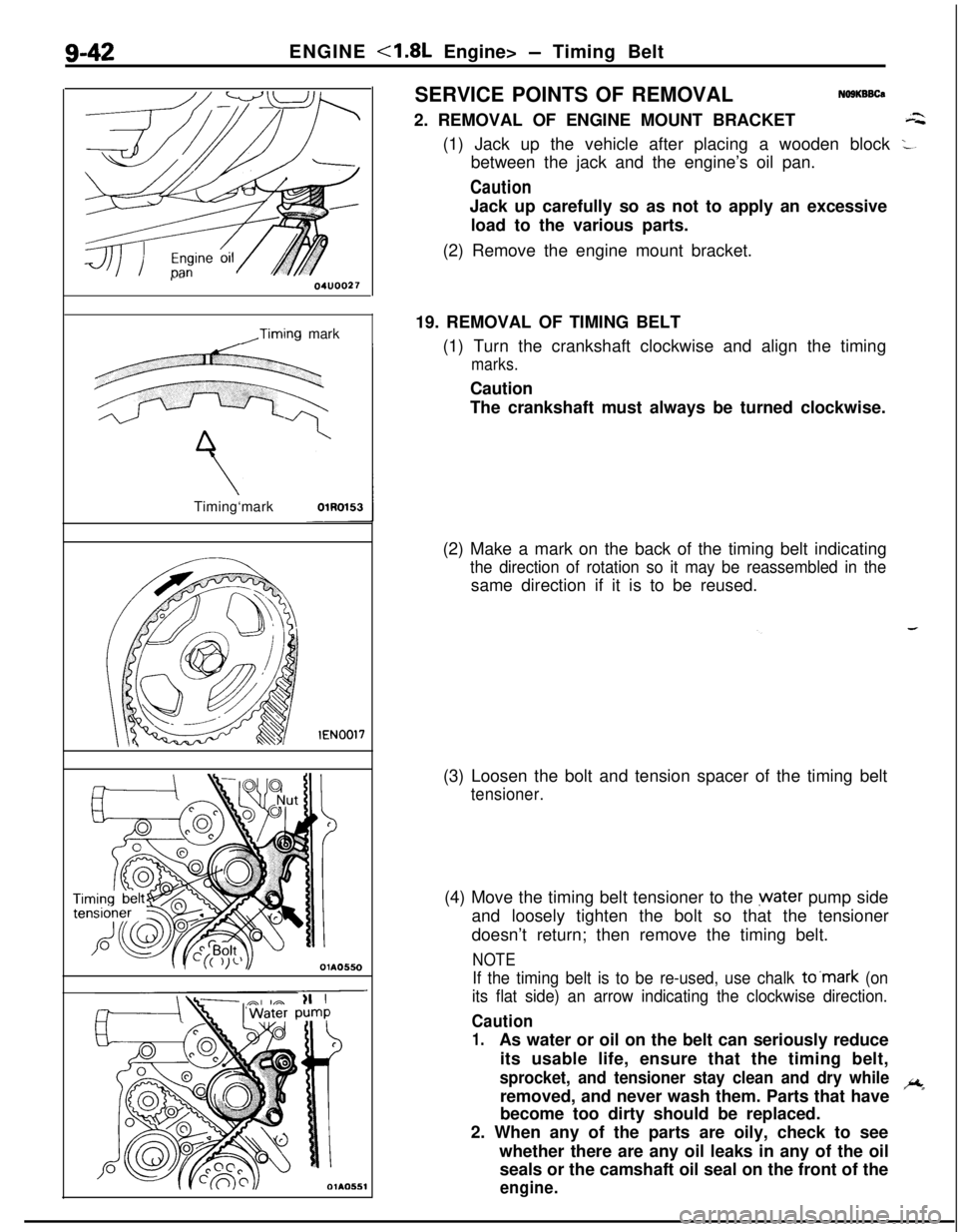
g-42ENGINE <1.8L Engine> - Timing Belt
r-04UOO27
,Timing mark
Timing‘mark
lEN0017
c
li
OlA0550SERVICE POINTS OF REMOVAL
NO9KBBCa2. REMOVAL OF ENGINE MOUNT BRACKET
a(1) Jack up the vehicle after placing a wooden block
:.between the jack and the engine’s oil pan.
CautionJack up carefully so as not to apply an excessive
load to the various parts.
(2) Remove the engine mount bracket.
19. REMOVAL OF TIMING BELT
(1) Turn the crankshaft clockwise and align the timing
marks.Caution
The crankshaft must always be turned clockwise.
(2) Make a mark on the back of the timing belt indicating
the direction of rotation so it may be reassembled in thesame direction if it is to be reused.
(3) Loosen the bolt and tension spacer of the timing belt
tensioner.(4) Move the timing belt tensioner to the water pump side
and loosely tighten the bolt so that the tensioner
doesn’t return; then remove the timing belt.
NOTE
If the timing belt is to be re-used, use chalk to’mark (on
its flat side) an arrow indicating the clockwise direction.
Caution
1.As water or oil on the belt can seriously reduce
its usable life, ensure that the timing belt,
sprocket, and tensioner stay clean and dry whileremoved, and never wash them. Parts that haveic
*become too dirty should be replaced.
2. When any of the parts are oily, check to see
whether there are any oil leaks in any of the oil
seals or the camshaft oil seal on the front of the
engine.
Page 381 of 1216
--ENGINE
<2.0L DOHC Engine> - Timing Belt9-97
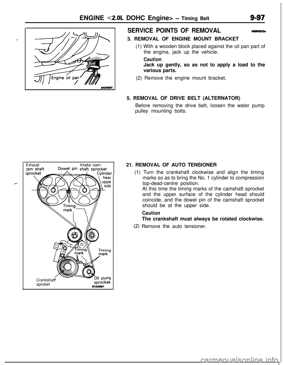
ExhaustIntake cam-
CrankshaftsproketsprockekOlhw51
1r
SERVICE POINTS OF REMOVAL-a3. REMOVAL OF ENGINE MOUNT BRACKET
(1) With a wooden block placed against the oil pan part of
the engine, jack up the vehicle.
CautionJack up gently, so as not to apply a load to the
various parts.
(2) Remove the engine mount bracket,
5. REMOVAL OF DRIVE BELT (ALTERNATOR)
Before removing the drive belt, loosen the water pump
pulley mounting bolts.
21. REMOVAL OF AUTO TENSIONER
(1) Turn the crankshaft clockwise and align the timing
marks so as to bring the No. 1 cylinder to compression
top-dead-centre position.
At this time the timing marks of the camshaft sprocket
and the upper surface of the cylinder head should
coincide, and the dowel pin of the camshaft sprocket
should be at the upper side.
CautionThe crankshaft must always be rotated clockwise.
(2‘) Remove the auto tensioner.
Page 616 of 1216
17-6REAR SUSPENSION
Drive out
BayArbor
Race
BearingSERVICE POINTS OF REMOVAL
Nl7QBh
1.REMOVAL OF REAR SPEED SENSOR
5-Wheel Speed Sensor.
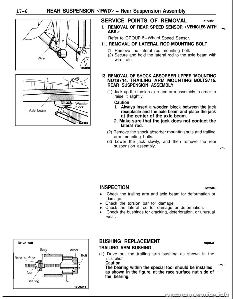
11. REMOVAL OF LATERAL ROD MOUNTING BOLT
(1) Remove the lateral rod mounting bolt.
(2) Secure and hold the lateral rod to the axle beam with
wire, etc.
13. REMOVAL OF SHOCK ABSORBER UPPER ‘MOUNTINGNUTS/14. TRAILING ARM MOUNTING BOLTS/15
REAR SUSPENSION ASSEMBLY(1) Jack up the torsion axle and arm assembly in order to
raise it slightly.
Caution
1.Always insert a wooden block between the jack
receptacle and the axle beam and place the jackat the center of the axle beam.
2. Make sure that the jack does not contact the
lateral rod.(2) Remove the shock absorber
m,ounting nuts and trailing
arm mounting bolts.
(3) Lower the jack slowly, and then remove the rear
suspension assembly.
#-
INSPECTIONNl7QCAL
lCheck the trailing arm and axle beam for deformation or
damage.l Check the torsion bar for damage.
l Check the lateral rod for damage or deformation.
lCheck the bushings for cracking, deterioration, or unusual
wear.
BUSHING REPLACEMENTNl)GTAE
TRAILING ARM BUSHING(1) Drive out the trailing arm bushing as shown in the
illustration.
Caution
The bearing within the special tool should be installed,
as shown in the figure, at the race surface nut side of7
the bearing.
Page 618 of 1216
17-8REAR SUSPENSION
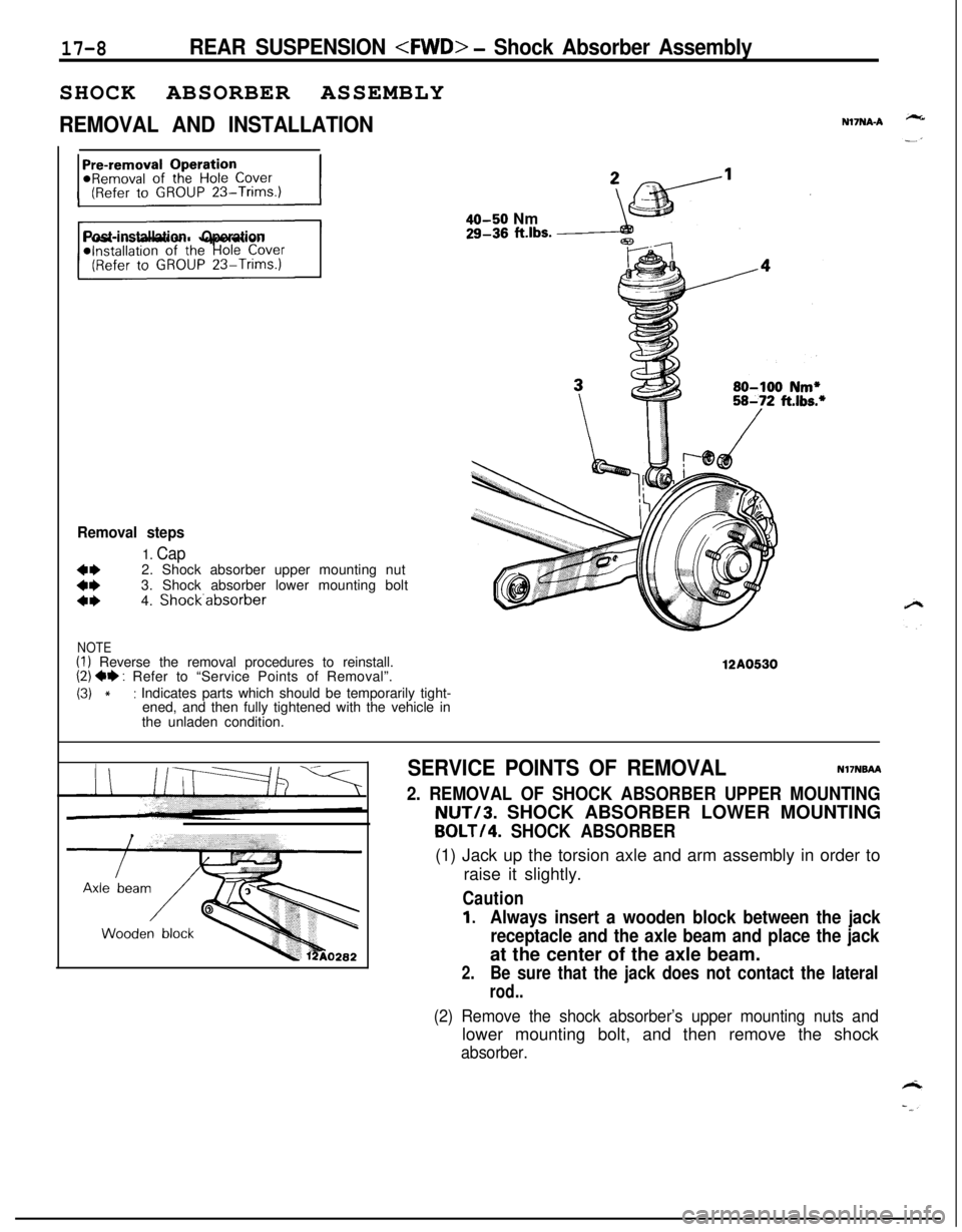
REMOVAL AND INSTALLATIONN17NA-A
Post-installation Operation
Removal steps
1. Cap
::2. Shock absorber upper mounting nut
3. Shock absorber lower mounting bolta*4. Shock.absorber
NOTE(I) Reverse the removal procedures to reinstall.(2) ** : Refer to “Service Points of Removal”.
(3) *: Indicates parts which should be temporarily tight-
ened, and then fully tightened with the vehicle in
the unladen condition.
40-50 Nm29-36 ft.lbs.
12A0530
SERVICE POINTS OF REMOVALNI’INBAA
2. REMOVAL OF SHOCK ABSORBER UPPER MOUNTINGNUT/3. SHOCK ABSORBER LOWER MOUNTING
BOLT/4. SHOCK ABSORBER(1) Jack up the torsion axle and arm assembly in order to
raise it slightly.
Caution
1.Always insert a wooden block between the jack
receptacle and the axle beam and place the jackat the center of the axle beam.
2.Be sure that the jack does not contact the lateral
rod..
(2) Remove the shock absorber’s upper mounting nuts andlower mounting bolt, and then remove the shock
absorber.
Page 623 of 1216
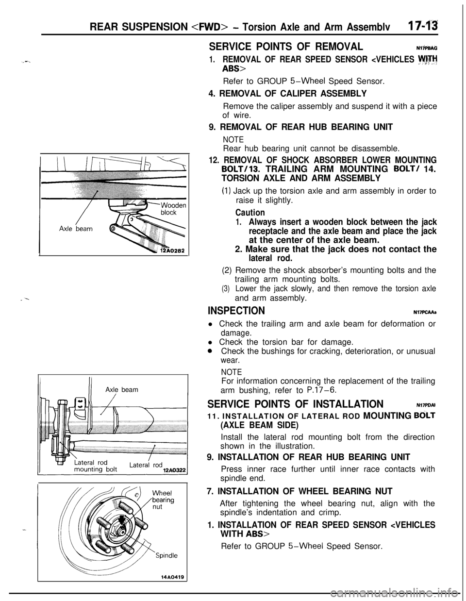
REAR SUSPENSION
Inut
-
-Spindle
14AO419
SERVICE POINTS OF REMOVALNliP9AG
1.REMOVAL OF REAR SPEED SENSOR
5-Wheel Speed Sensor.
4. REMOVAL OF CALIPER ASSEMBLYRemove the caliper assembly and suspend it with a piece
of wire.
9. REMOVAL OF REAR HUB BEARING UNIT
NOTERear hub bearing unit cannot be disassemble.
12. REMOVAL OF SHOCK ABSORBER LOWER MOUNTING
BOLT/lB. TRAILING ARM MOUNTING BOLT/ 14.
TORSION AXLE AND ARM ASSEMBLY
(1) Jack up the torsion axle and arm assembly in order to
raise it slightly.
Caution
1.Always insert a wooden block between the jack
receptacle and the axle beam and place the jackat the center of the axle beam.
2. Make sure that the jack does not contact the
lateral rod.(2) Remove the shock absorber’s mounting bolts and the
trailing arm mounting bolts.
(3)Lower the jack slowly, and then remove the torsion axleand arm assembly.
INSPECTIONN17PCAAa
l Check the trailing arm and axle beam for deformation or
damage.l Check the torsion bar for damage.
0Check the bushings for cracking, deterioration, or unusual
wear.
NOTEFor information concerning the replacement of the trailing
arm bushing, refer to
P.17-6.
SERVICE POINTS OF INSTALLATIONN17PDAI
11. INSTALLATION OF LATERAL ROD MOUNTING
BdLT
(AXLE BEAM SIDE)Install the lateral rod mounting bolt from the direction
shown in the illustration.
9. INSTALLATION OF REAR HUB BEARING UNITPress inner race further until inner race contacts with
spindle end.
7. INSTALLATION OF WHEEL BEARING NUTAfter tightening the wheel bearing nut, align with the
spindle’s indentation and crimp.
1. INSTALLATION OF REAR SPEED SENSOR
5-Wheel Speed Sensor.