power steering MITSUBISHI ECLIPSE 1991 Owner's Guide
[x] Cancel search | Manufacturer: MITSUBISHI, Model Year: 1991, Model line: ECLIPSE, Model: MITSUBISHI ECLIPSE 1991Pages: 1216, PDF Size: 67.42 MB
Page 450 of 1216
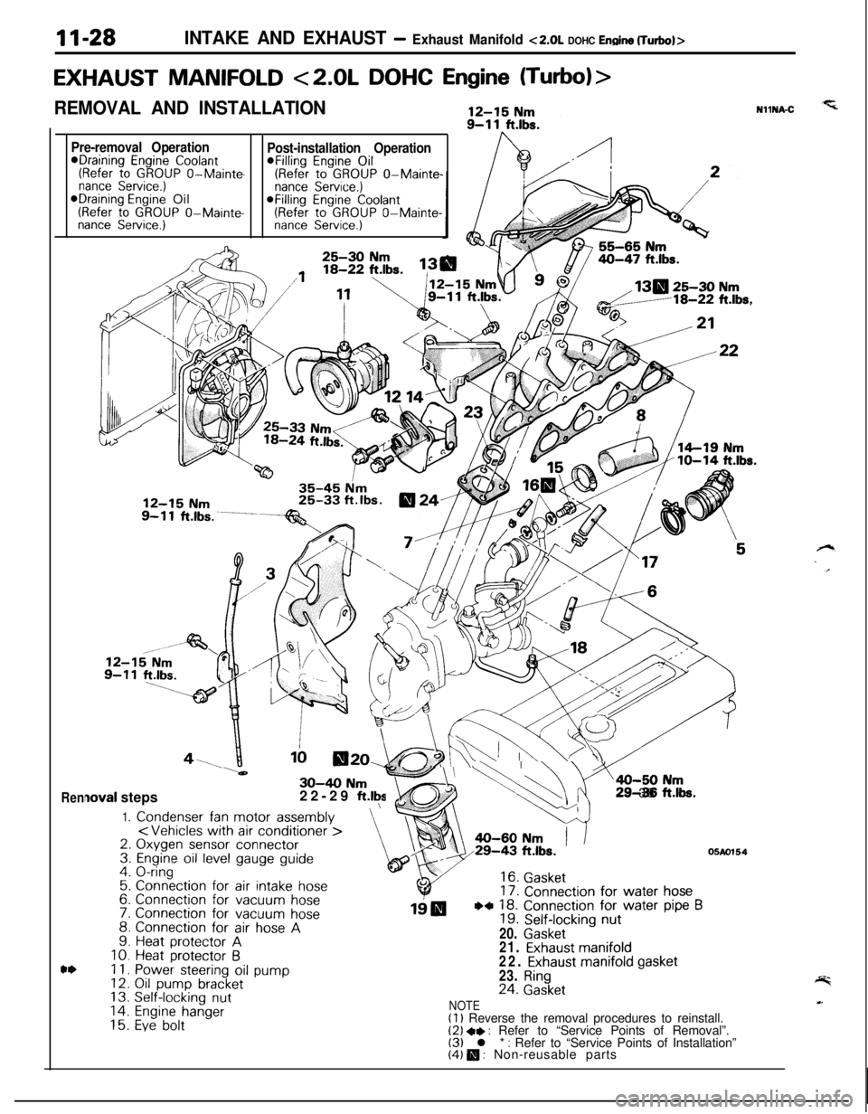
11-28INTAKE AND EXHAUST - Exhaust Manifold ~2.0~ DOHC Enoine (Turbo)>
EXHAUST MANIFOLD <2.0L DOHC Engine (Turbo)>
REMOVAL AND INSTALLATION
Pre-removal Operation*Draining Engine Coolant(Refer to GROUP O-Mainte-nance Service.)*Draining Engine Oil(Refer to GROUP O-Mainte-nance Service.)
Rennova1 steps
1.Condenser fan motor assembly
\30-40 Nm22-29 ft.lty3. & (
EJ\\=a-50 N
4 .ri29-38 ftk.
,
Post-installation Operation@Filling Engine Oil(Refer to GROUP O-Mainte-nance Service.)@Filling Engine Coolant(Refer to GROUP O-Mainte-nance Service.)NllNA-C
130 25-30 Nmd/18-22 ft.lbs.
;:4.
s5:7.
::10.Ii.12.13.14.15.
Connection for air intake hose
Connection for vacuum hoseConnection for vacuum hoseConnection for air hose AHeat protector AHeat protector 6Power steering oil pumpOil pump bracketSelf-locking nut
Engine hangerEve bolt
16. Gasket17. Connection for water hose
19IBWI 18. Connection for water pipe B19. Self-locking nut20.
Gasket
05Ao15421.
Exhaust manifold22. Exhaust manifold gasket23.
Ring24. Gasket
NOTE(1) Reverse the removal procedures to reinstall.(2) +, : Refer to “Service Points of Removal”.(3) l * : Refer to “Service Points of Installation”(4) m : Non-reusable parts
Page 451 of 1216
INTAKE AND EXHAUST - Exhaust Manifold
OlAO552
05K55;,
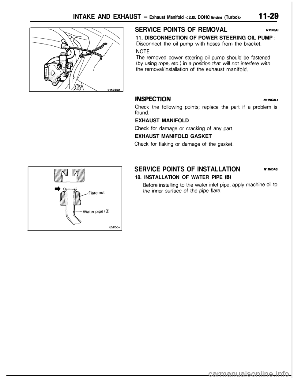
SERVICE POINTS OF REMOVALNllNBAl
11. DISCONNECTION OF POWER STEERING OIL PUMP
:
Disconnect the oil pump with hoses from the bracket.
NOTE
The removed power steering oil pump should be fastened
(by using rope, etc.) in a position that will not interfere with
the removal/installation of the exhaust manifold.
lNSPECTlONNllNCALl
Check the following points; replace the part if a problem is
found.EXHAUST MANIFOLD
Check for damage or cracking of any part.EXHAUST MANIFOLD GASKET
Check for flaking or damage of the gasket.
SERVICE POINTS OF INSTALLATIONNllNQAG
18. INSTALLATION OF WATER PIPE (BI
Before installing to the water inlet pipe, apply machine oil to
the inner surface of the pipe flare.
Page 455 of 1216
14-IFUEL SYSTEM
CONTENTS
AUTO-CRUISECONTROLSYSTEM...........................................109AUTO-CRUISECONTROL.......................................................140SERVICEADJUSTMENTPROCEDURES..............................135Accelerator Cable, Throttle Cable and Auto-cruise
ControlCableInspectionandAdjustment........................136Auto-cruise
ControlSystemInspection.............................135lndrvrdualPartsInspection..................................................137SPECIFICATIONS.....................................................................109GeneralSpecifications.......................................................109ServiceSpecifications
.........................................................109Torque Specrfications..........................................................109TROUBLESHOOTING...............................................................110Auto-CruiseControlCircurt................................................128Auto-cruise
ControlComponentsLocation........................126Auto-cruise Control Related Harnesses
.............................125Check Chart
........................................................................114Input Check.........................................................................123Self-diagnosis
Check..........................................................121Troubleshootrng
Quick-referenceChart..............................110ENGINECONTROL.......................................................................105ENGINECONTROL..................................................................107--SERVICEADJUSTMENTPROCEDURES..............................106Accelerator Cable Inspection and Adjustment..................106Accelerator Switch Inspectron and Adjustment................106SPECIFICATIONS.....................................................................105Lubricants.............................................................................105Sealant.................................................................................105ServiceSpecifications
..........................................................105TorqueSpecifications..........................................................105TROUBLESHOOTING...............................................................105FUELSYSTEM..............................................................................2FUELFILTER............................................................................104FUELLINEANDVAPORLINE..............................................102FUEL PUMP, FUEL GAUGE UNIT ANDOVERFILL LIMITER(TWO-WAY VALVE)
Switch........................................................64Air Conditioner Power Relay
..............................................67Components
Location......................................................56
ControlRelay
.................................................................66EGRControlSolenoidValve...............................................67EGRTemperatureSensor..................................................64Engine Coolant Temperature Sensor
.................................62IdlePosrtionSwitch
...........................................................63IdleSpeedControlServo
.............................
....................65InhibitorSwitch....................................................................65hjeCtOrS................................................................................65IntakeAirTemperatureSensor..........................................6’2MalfunctionlndtcatorLight
..........................................58MotorPosition
Sensor................................................63OxygenSensor
.................................................................64Power Steering 011 Pressure Swatch...........................65PowerTransistor
................................................................67PurgeControlSolenoidValve.........................................67
Self-Diagnosis.......................................................................
ThrottlePositronSensor.....................................................
Vehicle Speed Sensor.........................................................MPI
SYSTEMINSPECTION<2.0L DOHCEngine>...........Air Conditioner Power Relay..............................................
Arr Conditioner Swatch........................................................
Components Location
.........................................................
Control
Relay.......................................................................
EGR Control Solenoid Valve...............................................
EGR Temperature Sensor
...................................................
Engine Coolant Temperature Sensor
.................................Fuel Pressure Control Valve...............................................
Idle Position Switch
............................................................
Idle
SpeedControlServo...................................................Injectors
................................................................................
Intake Air Temperature Sensor..........................................
Malfunction Indicator Light.................................................
Oxygen Sensor
....................................................................
Power
Steering
OilPressureSwitch.................................Power Transistor
.................................................................
Purge Control Solenoid Valve.............................................
Self-Diaanosis.......................................................................
58
63
2382
79
688182
79
7682
77
79
79
76
727879
82
8273ThrottletiPosition Sensor
.....................................................77Vehicle Speed Sensor
.........................................................79SERVICE ADJUSTMENT PROCEDURES<1.8L Engine>........................................................................41Curb Idle Speed Inspection
................................................41EGR Valve Control Vacuum Check....................................47Fuel Pressure Test
..............................................................44Fuel Pump Operation Check
..............................................44Idle Speed Control and Throttle Position
Sensor Adjustment
..............................................................
41Purge Port Vacuum Check
.................................................47Release of Residual Pressure from
High Pressure Fuel Hose
...................................................
44Throttle
Body(Throttle Valve Area)Cleaning....................43SERVICE ADJUSTMENT PROCEDURES<2.0LDOHCEngine>............................................................48Basic Idle Speed Adjustment
.............................................
48
Curb Idle Speed Inspection
................................................48EGR Valve Control Vacuum Check....................................55Fuel Pressure Test
..............................................................52Fuel Pump Operation Check
..............................................51Idle Position Switch Adjustment........................................52Purge Port Vacuum Check
.................................................55Release of Residual Pressure from
High Pressure Fuel Hose
...................................................51Throttle Body (Throttle Valve Area) Cleaning....................51ThrottlePositionSensorAdjustment.................................50SPECIALTOOLS......................................................................6SPECIFICATIONS.....................................................................2GeneralSpecifications.........................................................2Sealant and Adhesive
.........................................................5Service Specifications
..........................................................4Torque Specifications
..........................................................5THROlTLEBODY<1.8LEngine>........................................85THROlTLE BODY <2.0L DOHC Engine>............................89TROUBLESHOOTING...............................................................6
Page 457 of 1216
FUEL SYSTEM - Specifications14-3
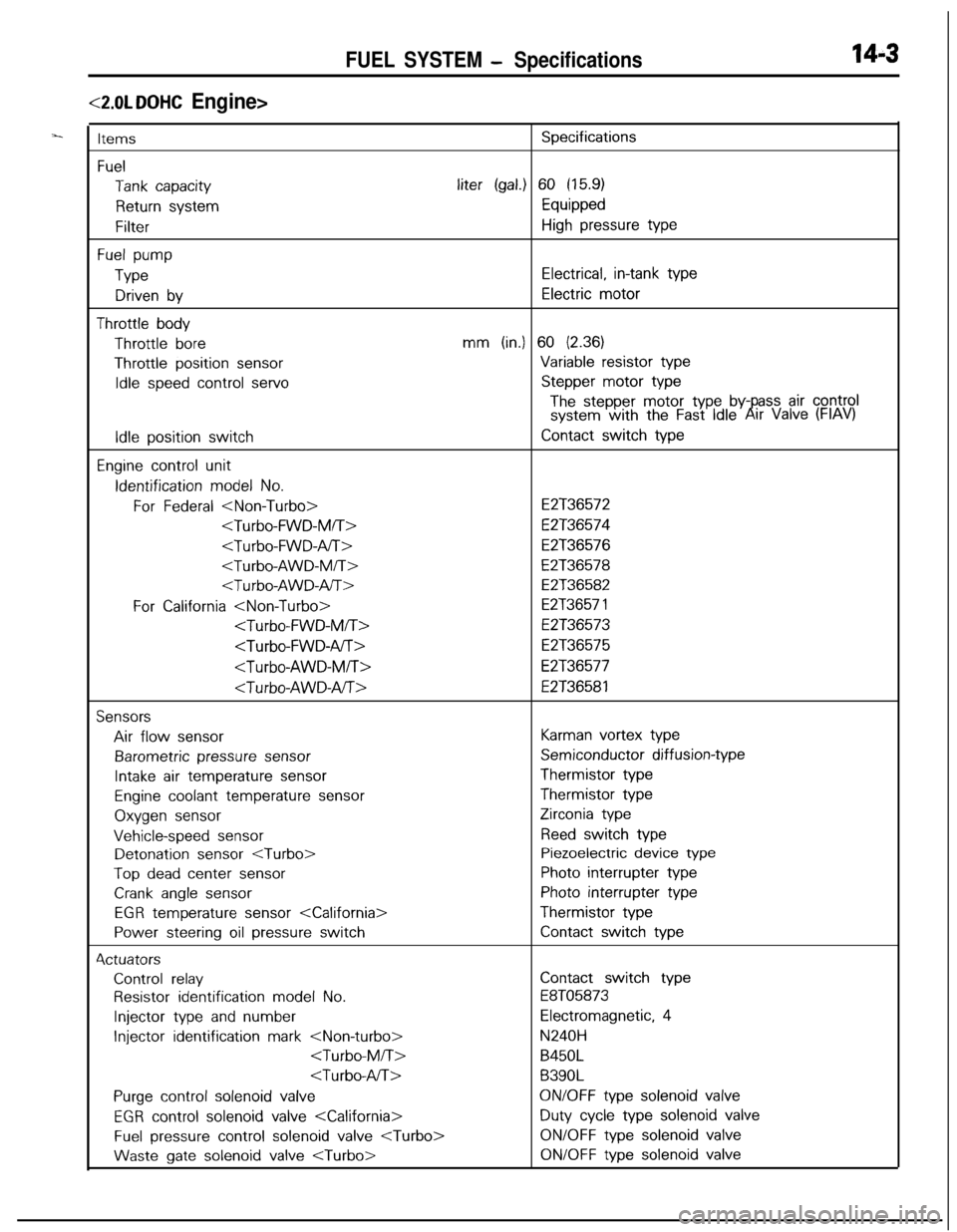
<2.0L DOHC Engine>
ItemsSpecifications
Fuel
Tank capacityliter (gal.) 60 (15.9)
Return systemEquipped
FilterHigh pressure type
Fuel pump
TypeElectrical, in-tank type
Driven byElectric motor
Throttle bodyThrottle
boremm (in.) 60 (2.36)Throttle position
sensorVariable resistor type
Idle speed control servoStepper motor type
The stepper motor type by- ass air controlsystem with the Fast Idle6!rr Valve (FIAV)
Idle position switchContact switch type
Engine control unitIdentification
model No.
For Federal
E2T36574
E2T36576
E2T36578
E2T36582
For California
E2T36573
E2T36575
E2T36577
E2T36581
SensorsAir flow
sensorKarman vortex type
Barometric pressure sensorSemiconductor diffusion-type
Intake air temperature sensorThermistor type
Engine coolant temperature sensorThermistor type
Oxygen sensorZirconia type
Vehicle-speed sensorReed switch typeDetonation
sensor
Top dead center sensorPhoto interrupter type
Crank angle sensorPhoto interrupter type
EGR temperature sensor
Power steering oil pressure switchContact switch type4ctuators
Control relayContact switch type
Resistor identification model No.E8T05873
Injector type and numberElectromagnetic, 4
Injector identification mark
B450L
B390L
Purge control solenoid valveON/OFF type solenoid valve
EGR control solenoid valve
Fuel pressure control solenoid valve
gate solenoid valve
Page 461 of 1216
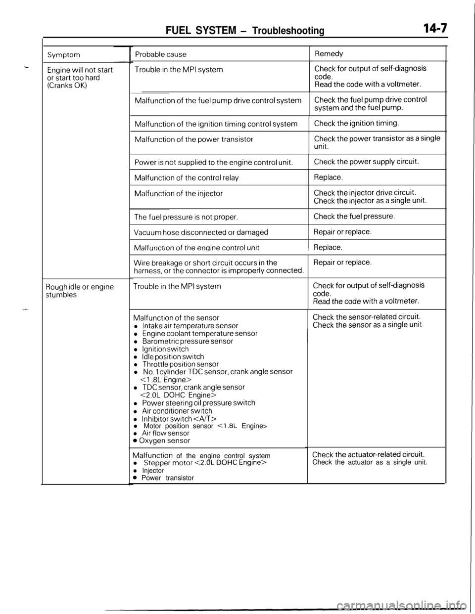
FUEL SYSTEM - Troubleshooting14-7
Symptom
Engine will not startor start too hard(Cranks OK)
Rough idle or engine
stumbles
Trouble in the MPI systemCheck for output of self-diagnosis
code.Read the code with a voltmeter.Malfunction
of the fuel pump drive control systemCheck the fuel pump drive controlsystem
and the fuel pump.Malfunction
of the ignition timing control systemMalfunction
of the power transistor
Check the ignition timing.
Check the power transistor as a single
unit.
Power is not supplied to the engine control unit.Check the power supply circuit.Malfunction
of the control relayMalfunction
of the injector
Replace.
Check the injector drive circuit.
Check the injector as a single unit.
The fuel pressure is not proper.Check the fuel pressure.
I
Vacuum hose disconnected or damagedRepair or replace.IMalfunction of
the engine control unit) Replace.
Wire breakage or short circuit occurs in theRepair or replace.
harness, or the connector is improperly connected.
Trouble in the MPI systemCheck for output of self-diagnosis
code.Read the code with a voltmeter.Malfunction
of the sensor
l Intake air temperature sensor
Check the sensor-related circuit.
Check the sensor as a single unit
Probable causeRemedy
l Engine coolant temperature sensorl Barometric pressure sensor
l Ignition switchl Idle position switchl Throttle position sensorl No. 1 cylinder TDC sensor, crank angle sensor
l TDC sensor, crank angle sensor<2.0L DOHC Engine>
l Power steering oil pressure switch
l Air conditioner switch
l Inhibitor switch l Motor position sensor <1.8L Engine>l Air flow sensor0 Oxygen sensorMalfunction of the engine control system
l
Stepper motor <2.0L DOHC Engine>l Injector0 Power transistor
Check the actuator-related circuit.Check the actuator as a single unit.
Page 462 of 1216
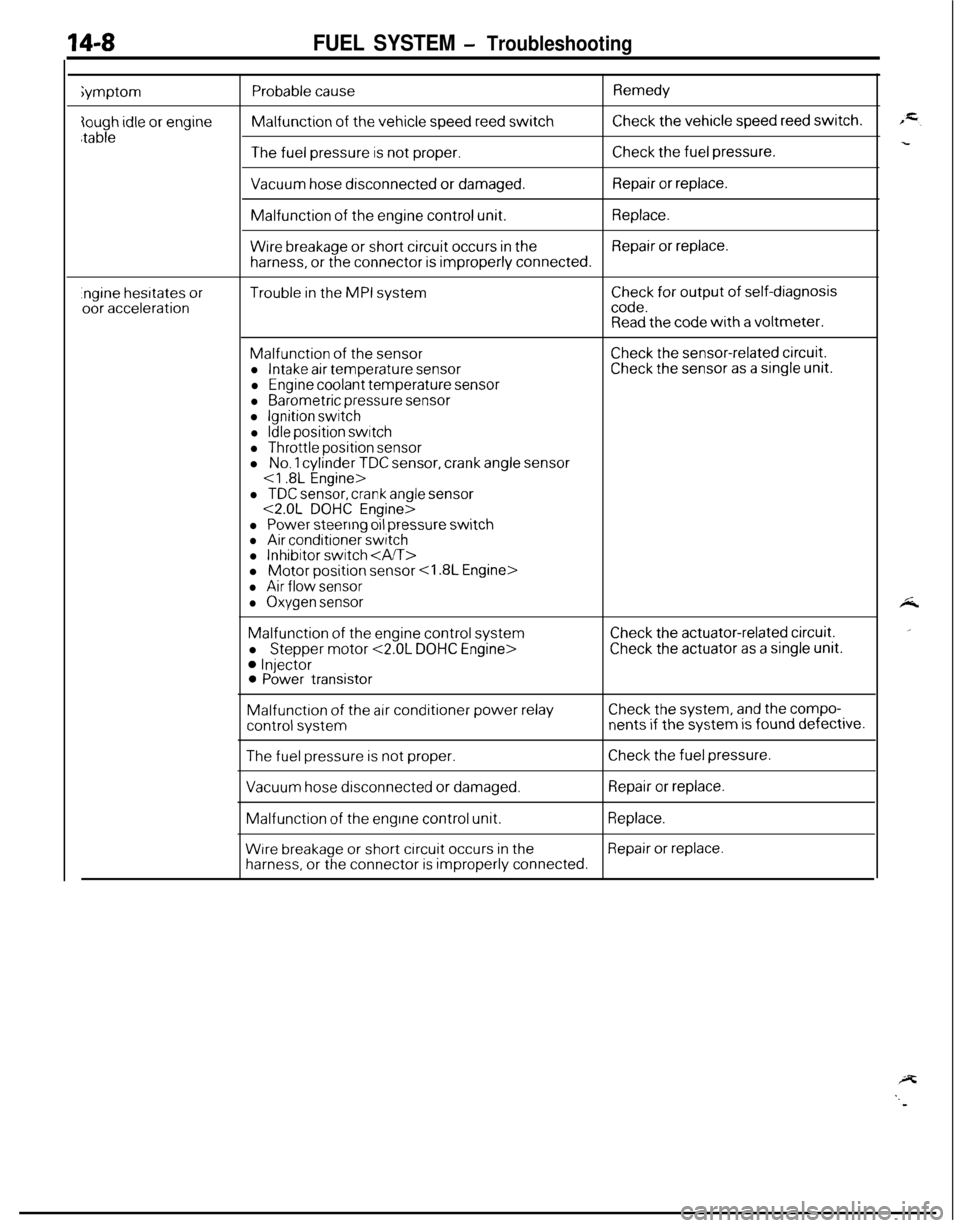
14-8FUEL SYSTEM - Troubleshootingiymptom
Probable causeMalfunction
of the vehicle speed reed switch
Remedy
Check the vehicle speed reed switch.
The fuel pressure is not proper.Check the fuel pressure.
Vacuum hose disconnected or damaged.Repair or replace.Malfunction
of the engine control unit.Replace.
Wire breakage or short circuit occurs in theRepair or replace.
harness, or the connector is improperly connected.
.ngine hesrtates oroor accelerationTrouble in the MPI systemCheck for output of self-diagnosiscode.Read the code with a voltmeter.
Malfunction of the sensorl Intake air temperature sensor
l Engine coolant temperature sensor
l Barometric pressure sensorl Ignition switch
l Idle position switchl Throttle position sensor
Check the sensor-related circuit.Check the sensor as a single unit.l
No. 1 cylinder TDC sensor, crank angle sensor
l TDC sensor, crank angle sensor<2.0L DOHC Engine>
l Power steering oil pressure switchl Air conditioner switchl Inhibitor switch l Motor position sensor
l Air flow sensor
l Oxygen sensorMalfunction
of the engine control system
l
Stepper motor <2.0L DOHC Engine>
0 Injector0 Power transistor
Check the actuator-related circuit.
Check the actuator as a single unit.Malfunction
of the air conditioner power relayCheck the system, and the compo-
control systemnents if the system is found defective.
The fuel pressure is not proper.Check the fuel pressure.
Vacuum hose disconnected or damaged.Repair or replace.Malfunction
of the engine control unit.Replace.
Wrre breakage or short circuit occurs in theRepair or replace.
harness, or the connector is improperly connected.
Page 463 of 1216
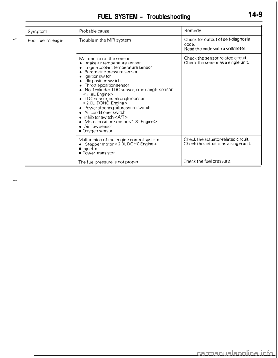
FUEL SYSTEM - Troubleshooting14-S
Symptom
Poor fuel mileage,
Probable cause
Trouble In the MPI system
Remedy
Check for output of self-diagnosis
code.Read the code with a voltmeter.Malfunction
of the sensorl Intake air temperature sensorl Engine coolant temperature sensorl Barometric pressure sensorl Ignition switchl Idle position switch
l Throttle position sensorl No. 1 cylinder TDC sensor, crank angle sensor
Check the sensor-related circuit.Check the sensor as a single unit.
l TDC sensor, crank angle sensor<2.0L DOHC Engine>
l Power steering oil pressure switch
l Air conditioner switch
l lnhrbrtor switch l Motor
position sensor
l Air flow sensor
0 Oxygen sensor
Malfunction of the engine control system
l Stepper motor <2.0L DOHC Engine>
0 Injector0 Power transistor
Check the actuator-related circurt.Check the actuator as a single unit.
The fuel pressure is not proper.Check the fuel pressure.
Page 465 of 1216
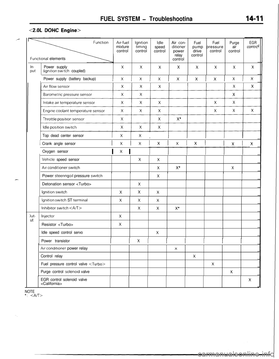
FUEL SYSTEM - Troubleshootina
<2.0LDOHC Engine>
FunctronArr-fuellgnrtronIdleAir con-
FuelFuel
PurgeEGRmixturetimrng
speeddrtronerpump pressureaircontrc
controlcontrol
controlpowerdrivecontrol
control
relaycontrol
Functronal elementscontrol
InPower supplyXXXXXXXXPut(ignrtron switch coupled)
Power supply (battery backup)
Ix Ix Ix lx lx lx lx Ix
Top dead center sensorI xXI
1 Crank angle sensorIxlxIxIxIxI lxlx
Oxygen sensorI x I
Vehrcle speed sensor
Air conditioner switch
XX
XX”XPower steering
011 pressure switchXIDetonation sensor
lgnrtron switch
X
XXX
lgnrtron switch ST terminalXXX
lnhibrtor switch XXX”
)ut-InjectorXutResistor
Idle speed control servoX
Power transistorI 1x1 I I I I I
Arr condrtroner power relay
Control relay
Fuel pressure control valve
Purge control solenord valve
X
X
X
X
EGR control solenoid valve
NOTE*:
Page 477 of 1216

FUEL SYSTEM - Troubleshootinn
-.
_-
AIR FLOW SENSORr
INTAKK AlN AlNTENPERAIURE PLOUEENBOR BENBORA-36
q_-____-____--_ -----------5
T
14
c
----.19
Ic
21
lfl
2ON3OFF
Y
IDLESWITCH=4 EGR TEMPERATURE ENGINETHROTTLE
fi %i%kES FORPOSITION
CALIFORNIA)
B-08 mB-30 I
Ia
{mc
B-05
mPOWER
STEERING OIL
Pl?l?f;#RE
KX35-AC-UOBlBA-NC
Page 482 of 1216
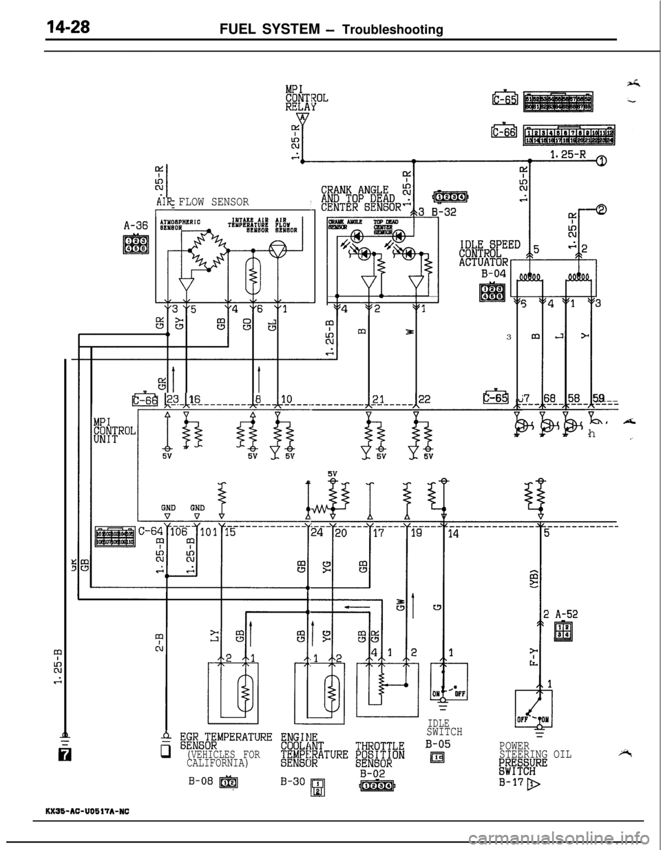
14-28FUEL SYSTEM - Troubleshooting
9,AIR FLOW SENSOR
A-36
B-043
IDI-6
3
*
I&59- ----h
c
T--
3j8
--_it%$ k-3 116- ----------lLLlU------------12J-----122
------------i
=
POWER
STEERING OIL
;;%fE;RE
B-17D
OH12OFF
IDLESWITCH
B-05
ml
! A-52
$ ;giZG;$MPERATURE ENGIIIE
q (VEHICLES FORCOOLiiNT
CALIFORNIA)@bE$ATURE ~~ti%&i
B-30 1B-02
Hfg&iJ
KX36-AC-U0617A-NC