power steering MITSUBISHI ECLIPSE 1991 Workshop Manual
[x] Cancel search | Manufacturer: MITSUBISHI, Model Year: 1991, Model line: ECLIPSE, Model: MITSUBISHI ECLIPSE 1991Pages: 1216, PDF Size: 67.42 MB
Page 495 of 1216
FUEL SYSTEM - Service Adjustment Procedures <1.8L Engine>l-4-41
SERVICE ADJUSTMENT PROCEDURES
CURB IDLE SPEED INSPECTION
CautionNlIFiiAE
The improper setting (throttle valve opening) will increase
exhaust gas temperature at deceleration, reducing catalystlife greatly and deteriorating exhaust gas cleaning per-
formance. It also has effect on fuel consumption and
engine braking.
ilter
Paper clip
16A0898
PI-e-conditions for inspection
0Engine coolant temperature: 85-95°C (185-205°F)
0Lights, electric cooling fan and accessories: OFF
l Transaxle: Neutral
(P for vehicles with an automatic
transaxle)l Steering wheel: Neutral position (vehicles with a power
steering)l Check ignition timing and adjust if necessary. Refer to
GROUP 8.
NOTEWith vehicles for Canada, the headlights and taillights, etc.
remain on even when the lighting switch is turned OFF, but thiscauses no problems during inspection.
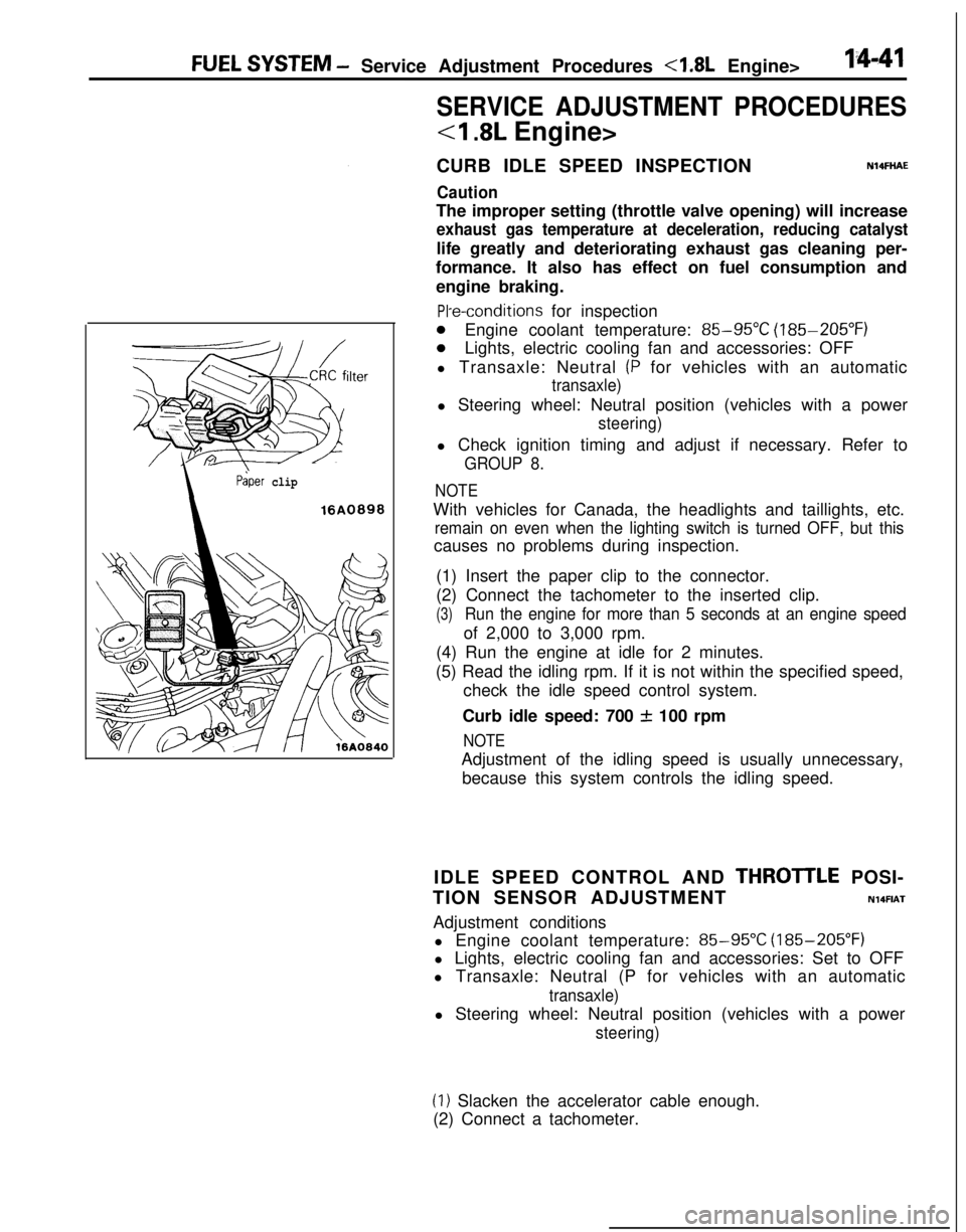
(1) Insert the paper clip to the connector.
(2) Connect the tachometer to the inserted clip.
(3)Run the engine for more than 5 seconds at an engine speedof 2,000 to 3,000 rpm.
(4) Run the engine at idle for 2 minutes.
(5) Read the idling rpm. If it is not within the specified speed,
check the idle speed control system.
Curb idle speed: 700
f 100 rpm
NOTEAdjustment of the idling speed is usually unnecessary,
because this system controls the idling speed.
IDLE SPEED CONTROL AND
THROTlLE POSI-
TION SENSOR ADJUSTMENT
N14FIATAdjustment conditions
l Engine coolant temperature:
85-95X (185-205°F)
l Lights, electric cooling fan and accessories: Set to OFF
l Transaxle: Neutral (P for vehicles with an automatic
transaxle)l Steering wheel: Neutral position (vehicles with a power
steering)
(1) Slacken the accelerator cable enough.
(2) Connect a tachometer.
Page 502 of 1216
14-48FUEL SYSTEM - Service Adjustment Procedures <2.0L Engine>
SERVICE ADJUSTMENT PROCEDURES
<2.0L DOHC Engine>
CURB IDLE SPEED INSPECTION
Caution
N14FHADThe improper setting (throttle valve opening) will increase
exhaust gas temperature at deceleration, reducing
catalys-tic converter life greatly and deteriorating exhaust gas
cleaning performance. It also has effect on fuel ‘consump-
tion and engine braking.
Pre-conditions for inspection
l Engine coolant temperature:
85-95°C (185-205°F)
l Lights, electric cooling fan and accessories: OFF
lTransaxle: Neutral (P for vehicles with automatic transaxle)l Steering wheel: Neutral position (vehicles with a power-
steering)l Check ignition timing and adjust if necessary. Refer to
GROUP 8.
NOTEWith vehicles for Canada, the headlights and taillights, etc.
remain on even when the lighting switch is turned OFF, but thiscauses no problems during inspection.
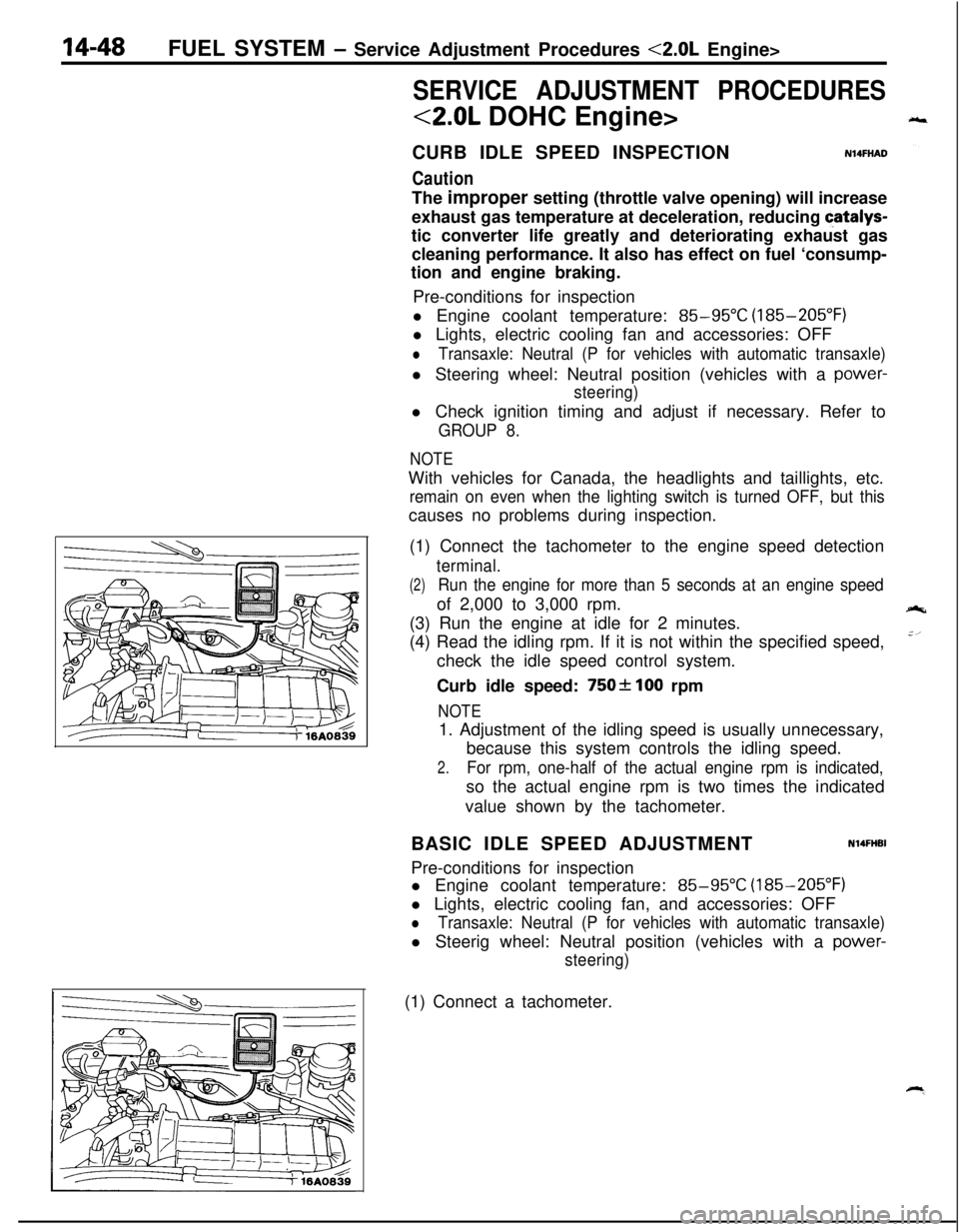
(1) Connect the tachometer to the engine speed detection
terminal.
(2)Run the engine for more than 5 seconds at an engine speedof 2,000 to 3,000 rpm.
(3) Run the engine at idle for 2 minutes.
(4) Read the idling rpm. If it is not within the specified speed,
check the idle speed control system.
Curb idle speed:
750f 100 rpm
NOTE1. Adjustment of the idling speed is usually unnecessary,
because this system controls the idling speed.
2.For rpm, one-half of the actual engine rpm is indicated,so the actual engine rpm is two times the indicated
value shown by the tachometer.
BASIC IDLE SPEED ADJUSTMENT
N14FHBIPre-conditions for inspection
l Engine coolant temperature:
85-95°C (185-205°F)
l Lights, electric cooling fan, and accessories: OFF
lTransaxle: Neutral (P for vehicles with automatic transaxle)l Steerig wheel: Neutral position (vehicles with a
power-
steering)(1) Connect a tachometer.
Page 519 of 1216
FUEL SYSTEM - MPI Svstem InsDection <1.8L Engine>14-65
3FUO349
/--
’ 3FU03991
Idle speed controlservo connector(motor side, front view)
3FUO393
INHIBITOR SWITCHN14QRACsRefer to GROUP 21
- Service Adjustment Procedures.
POWER STEERING OIL PRESSURE SWITCH
N14flCJBRefer to GROUP 19 for power steering system inspection.
INJECTORSN14QTAGCHECKING OPERATION SOUND
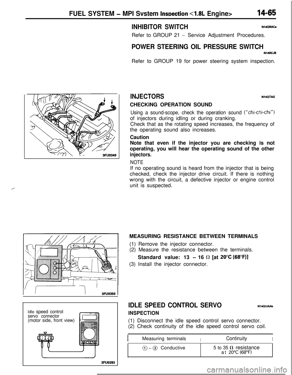
Using a sound-scope, check the operation sound (“chi-chi-chi”)of injectors during idling or during cranking.
Check that as the rotating speed increases, the frequency of
the operating sound also increases.
Caution
Note that even if the injector you are checking is not
operating, you will hear the operating sound of the other
injectors.
NOTEIf no operating sound is heard from the injector that is being
checked, check the injector drive circuit. If there is nothing
wrong with the circuit, a defective injector or engine control
unit is suspected.
MEASURING RESISTANCE BETWEEN TERMINALS
(1) Remove the injector connector.
(2) Measure the resistance between the terminals.
Standard value: 13
- 16 L(Z [at 20°C (68”F)I(3) Install the injector connector.
IDLE SPEED CONTROL SERVO
INSPECTION
NlQQUAAb(1) Disconnect the idle speed control servo connector.
(2) Check continuity of the idle speed control servo coil.
IMeasuring terminalsIContinuityI
@ - @ Conductive5 to 35 fi resistance
at 20°C (68°F)
Page 523 of 1216
![MITSUBISHI ECLIPSE 1991 Workshop Manual FUEL SYSTEM - MPI System Inspection <2.0L DOHC Engine>
EGR control solenoid valve
[Calif. only]
Purge control solenoid valve
1
/AF--Y:rIgnition coil, Power transistor
Oxygen sensorPower
steering flu MITSUBISHI ECLIPSE 1991 Workshop Manual FUEL SYSTEM - MPI System Inspection <2.0L DOHC Engine>
EGR control solenoid valve
[Calif. only]
Purge control solenoid valve
1
/AF--Y:rIgnition coil, Power transistor
Oxygen sensorPower
steering flu](/img/19/57104/w960_57104-522.png)
FUEL SYSTEM - MPI System Inspection <2.0L DOHC Engine>
EGR control solenoid valve
[Calif. only]
Purge control solenoid valve
1
/AF--Y:rIgnition coil, Power transistor
Oxygen sensorPower
steering fluid Dressure switch
Coolant temDerature sensor
Page 525 of 1216

FUEL SYSTEM - MPI System Inspection <2.0L DOHC Engine>
InjectorII
01A0499
/
Purge control
Fuel pressureII solenoid valve
control valve
solenoid valve
0110503Ignition coil, Power transistor
IOxvnen sensorEGR control solenoid valve
[Calif. only]
Purge control solenoid valve
Fuel pressure control valve [Turbo only]
\’
\
16A0803Detonation sensor
\Power steering fluid oressure switch
Page 533 of 1216
FUEL SYSTEM - MPI System Inspection <2.0L QOHC Engine>14-79EGR TEMPERATURE SENSOR
N14RCHAaRefer to GROUP 25
- Exhaust Gas Recirculation System.
VEHICLE SPEED SENSOR
Refer to GROUP 8
- Meters and Gauges.
N140EBBaAIR CONDITIONER SWITCH
Nl4QQAEaRefer to GROUP 8
- Column Switch.
POWER STEERING OIL PRESSURE SWITCH
N14RCJBRefer to GROUP 19 for power steering system inspection.
INJECTORS
NWXAHCHECKING OPERATION SOUND
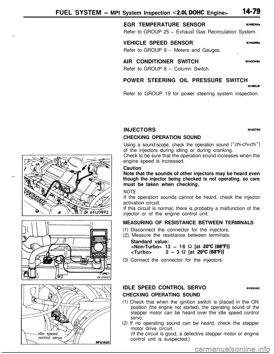
Using a sound-scope, check the operation sound (“chi-chi-chi”)of the injectors during idling or during cranking.
Check to be sure that the operation sound increases when the
engine speed is increased.
Caution
Note that the sounds of other injectors may be heard even
though the injector being checked is not operating, so caremust be taken when checking.
NOTEIf the operation sounds cannot be heard, check the injector
activation circuit.
If this circuit is normal, there is probably a malfunction of the
injector or of the engine control unit.
MEASURING OF RESISTANCE BETWEEN TERMINALS
(1) Disconnect the connector for the injectors.
(2) Measure the resistance between terminals.
Standard value:
-16 S2 [at 20°C (68”F)]
- 3 52 [at 20% (68”F)]
(3) Connect the connector for the injectors.
IDLE SPEED CONTROL SERVO
N14QUADCHECKING OPERATING SOUND
(1) Check that when the ignition switch is placed in the ON
position (the engine not started), the operating sound of thestepper motor can be heard over the idle speed control
servo.
(2) If no operating sound can be heard, check the stepper
motor drive circuit.
(If the circuit is good, a defective stepper motor or engine
control unit is suspected.)
Page 649 of 1216
STEERING
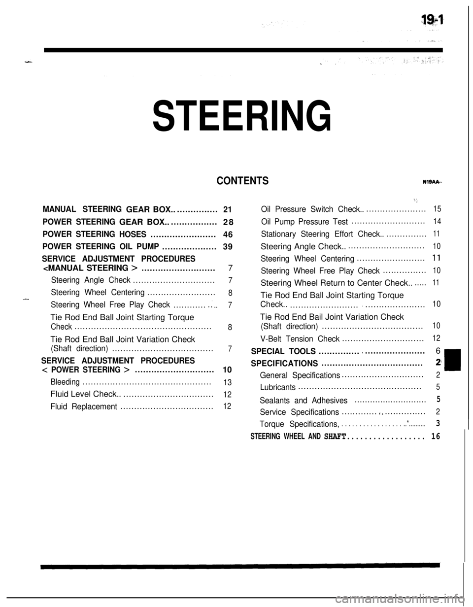
CONTENTSNISAA-
MANUAL STEERINGGEAR BOX.................21
POWER STEERINGGEAR BOX...................
28
POWER STEERING
HOSES........................
46
POWER STEERING OIL PUMP....................39
SERVICE ADJUSTMENT PROCEDURES
Steering Angle Check..............................7
Steering Wheel Centering.........................8
Steering Wheel Free Play Check.............:..7Tie Rod End Ball Joint Starting Torque
Check..................................................8Tie Rod End Ball Joint Variation Check
(Shaft direction).....................................7
SERVICE ADJUSTMENT PROCEDURES
< POWER STEERING >.............................
10
Bleeding...............................................13Fluid Level Check...................................
12
Fluid Replacement..................................12
i;,
Oil Pressure Switch Check........................15
Oil Pump Pressure Test...........................14
Stationary Steering Effort Check.................11Steering Angle Check..............................
10
Steering Wheel Centering.........................1 1
Steering Wheel Free Play Check................10Steering Wheel Return to Center Check.......
11Tie Rod End Ball Joint Starting Torque
Check..................................................10Tie Rod End Bail Joint Variation Check
(Shaft direction).....................................10
V-Belt Tension Check..............................12
SPECIAL TOOLS......................................6
SPECIFICATIONS.....................................2;
General Specifications..............................2
Lubricants.............................................5
Sealants and Adhesives............................5
Service Specifications.............‘................2
Torque Specifications,. . . . . . . . . . . . . . . . . ..*..........3
STEERING WHEEL AND SHAFT.................. 16
Page 650 of 1216
19-2STEERING - Specifications
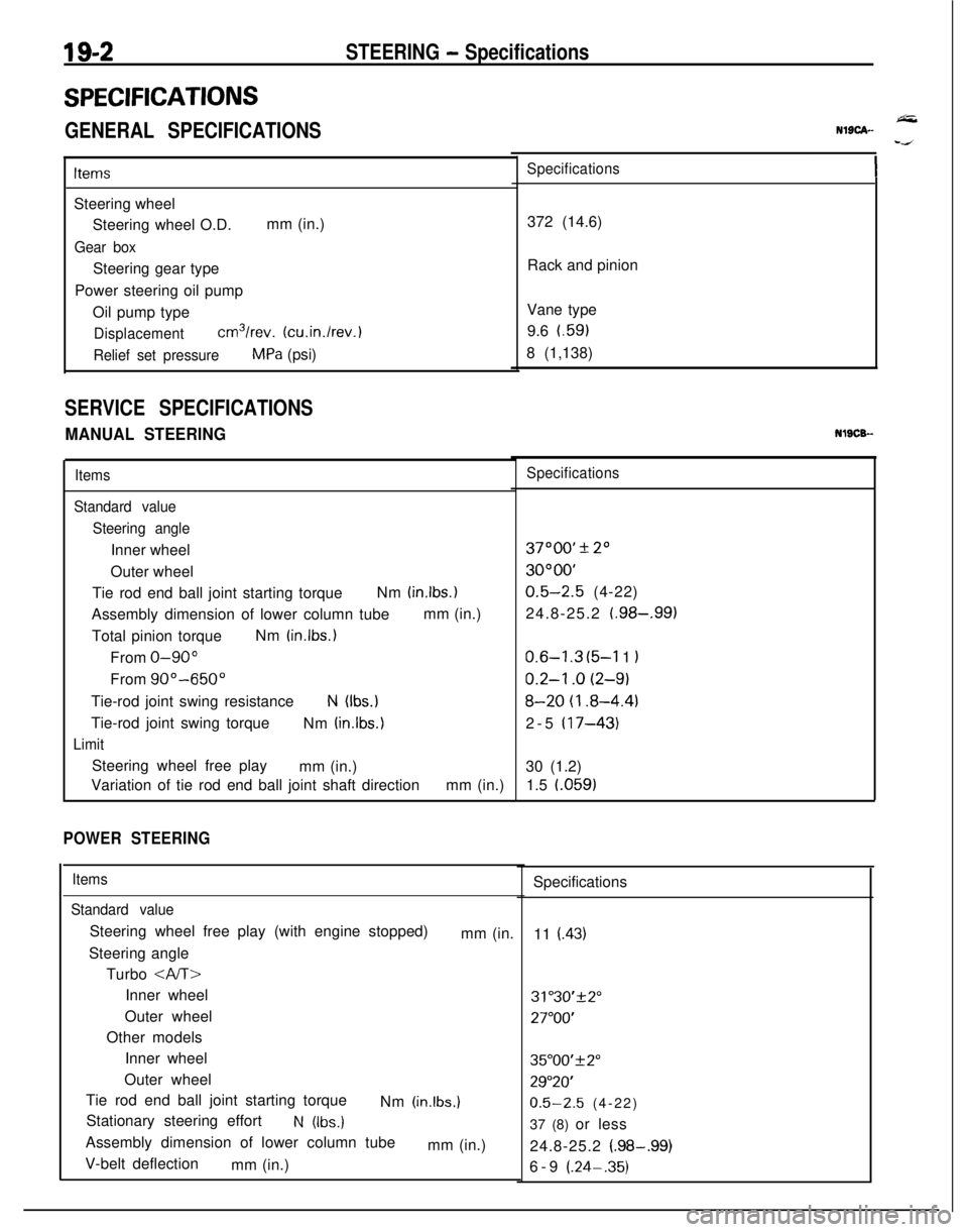
SPECIFICATIONS
GENERAL SPECIFICATIONS
ItemsSteering wheel
Steering wheel O.D.mm (in.)
Gear boxSteering gear type
Power steering oil pump
Oil pump type
Displacementcm3/rev. (cu.in./rev.)
Relief set pressureMPa (psi)
SERVICE SPECIFICATIONS
MANUAL STEERING
Items
Standard value
Steering angleInner wheel
Outer wheel
Tie rod end ball joint starting torqueNm
(in.lbs.)Assembly dimension of lower column tubemm (in.)
Total pinion torqueNm
(in.lbs.)From
O-90”From
90”-650”Tie-rod joint swing resistance
N (Ibs.)Tie-rod joint swing torque
Nm
(in.lbs.)
LimitSteering wheel free play
mm (in.)
Variation of tie rod end ball joint shaft directionmm (in.)
POWER STEERING
Items
Standard valueSteering wheel free play (with engine stopped)
mm (in.
Steering angle
Turbo
Inner wheel
Outer wheel
Other models
Inner wheel
Outer wheel
Tie rod end ball joint starting torque
Nm
(in.lbs.)Stationary steering effort
N (Ibs.)Assembly dimension of lower column tube
mm (in.)
V-belt deflection
mm (in.)
NlSCA--
Specifications372 (14.6)
Rack and pinion
Vane type
9.6 t.59)
8 (1,138)NlSCB-
Specifications37000’
* 20
3OOOO’
0.5-2.5 (4-22)
24.8-25.2
(.98-,991
0.6-l .3 (5-l 1 I
0.2-l .o (2-9)
8-20 (I .8-4.4)2-5
(17-43)30 (1.2)
1.5 l.059)
Specifications
11
(.43)
31"30'+2"
27"OO'
35"00'f2"
29"20'
0.5-2.5 (4-22)
37 (8) or less
24.8-25.2
(.98-.99)6-9 (.24-.35)
Page 652 of 1216
19-4STEERING - Specifications
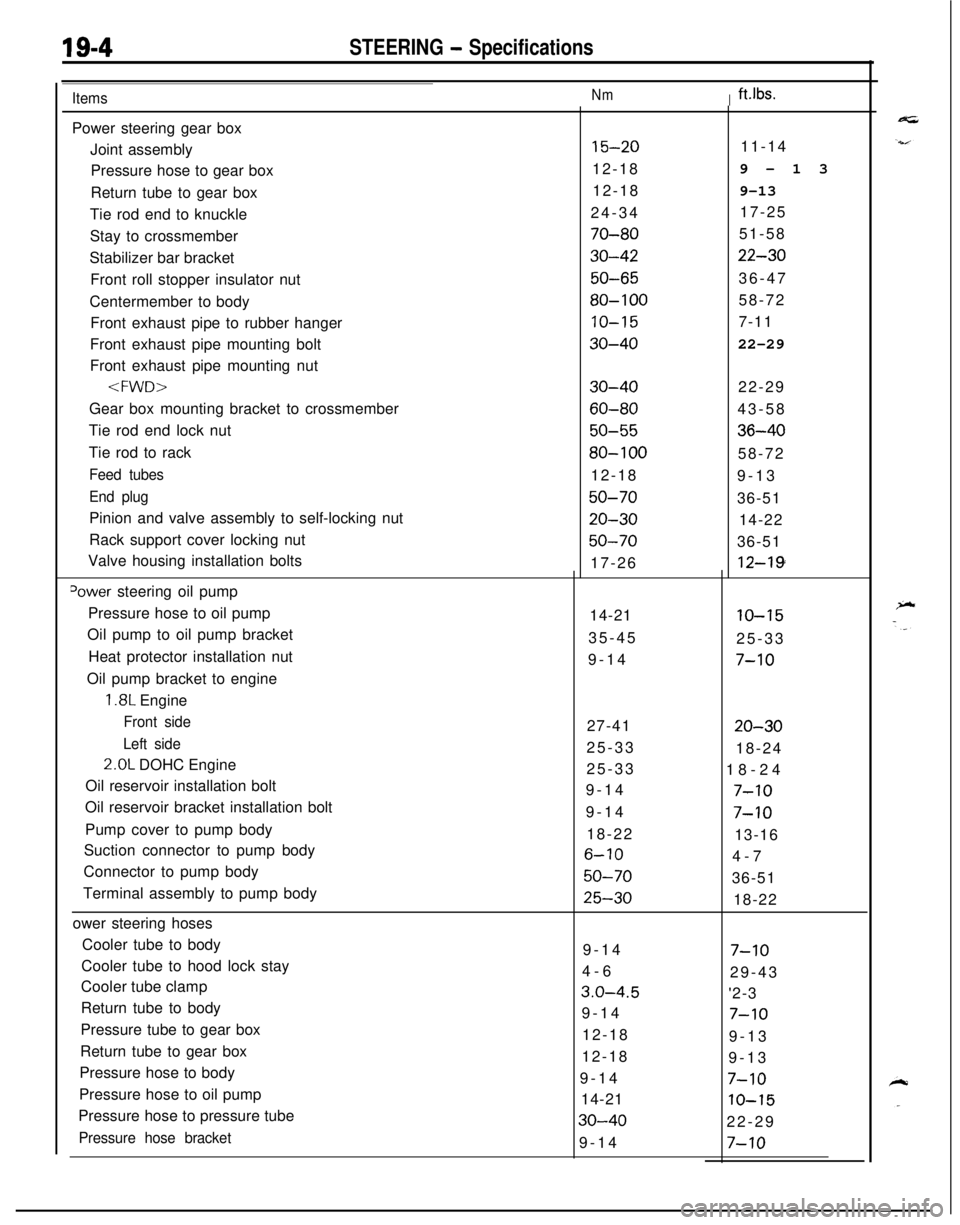
ItemsNmIft.lbs.Power steering gear box
Joint assembly
Pressure hose to gear box
Return tube to gear box
Tie rod end to knuckle
Stay to crossmember
Stabilizer bar bracket
Front roll stopper insulator nut
Centermember to body
Front exhaust pipe to rubber hanger
Front exhaust pipe mounting bolt
Front exhaust pipe mounting nut
Tie rod end lock nut
Tie rod to rack
Feed tubes
End plugPinion and valve assembly to self-locking nut
Rack support cover locking nut
Valve housing installation bolts
Power steering oil pump
Pressure hose to oil pump
Oil pump to oil pump bracket
Heat protector installation nut
Oil pump bracket to engine
1.8L Engine
Front side
Left side2.0L DOHC Engine
Oil reservoir installation bolt
Oil reservoir bracket installation bolt
Pump cover to pump body
Suction connector to pump body
Connector to pump body
Terminal assembly to pump body
ower steering hoses
Cooler tube to body
Cooler tube to hood lock stay
Cooler tube clamp
Return tube to body
Pressure tube to gear box
Return tube to gear box
Pressure hose to body
Pressure hose to oil pump
Pressure hose to pressure tube
Pressure hose bracket11-14
9-13
9-13
17-25
51-58
22-3036-47
58-72
7-11
22-29
22-29
43-58
36-4058-72
9-13
36-51
14-22
36-51
12-19
15-2012-18
12-18
24-34
70-80
30-42
50-65
80-100
10-15
30-40
30-40
60-80
50-55
80-10012-18
50-70
20-30
50-7017-26
14-21
10-1535-45
25-33
9-14
7-1027-41
20-3025-33
18-24
25-33
18-24
9-14
7-109-14
7-1018-22
13-16
6-104-7
50-7036-51
25-3018-22
9-14
7-104-6
29-43
3.0-4.5'2-3
9-14
7-1012-18
9-13
12-18
9-13
9-14
7-1014-21
IO-15
30-4022-29
9-14
7-10
Page 653 of 1216
STEERING - Smcifications
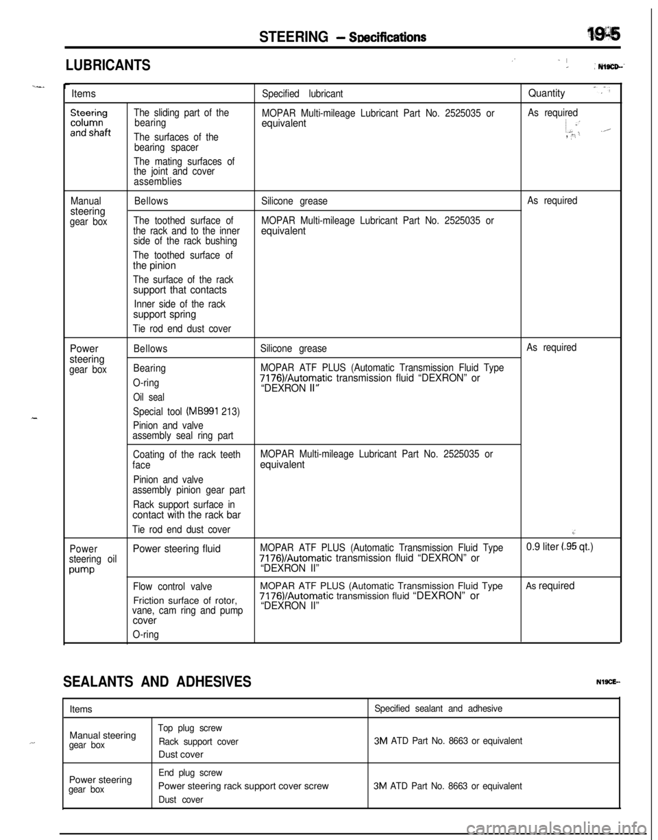
LUBRICANTS_’” I_: Nls%D--
ItemsSpecified lubricantQuantity
The sliding part of the
bearing
The surfaces of the
bearing spacer
The mating surfaces of
the joint and cover
assembliesMOPAR Multi-mileage Lubricant Part No. 2525035 orequivalentAs required~ 8’i-.A
, ” ‘i
Manualsteeringgear boxBellows
The toothed surface of
the rack and to the inner
side of the rack bushing
The toothed surface of
the pinion
The surface of the racksupport that contacts
Inner side of the racksupport spring
Tie rod end dust coverSilicone grease
MOPAR Multi-mileage Lubricant Part No. 2525035 or
equivalent
As required
Power
steering
gear boxBellows
Bearing
O-ring
Oil seal
Special tool (MB991 213)
Pinion and valve
assembly seal ring partSilicone grease
MOPAR ATF PLUS (Automatic Transmission Fluid Type
7176VAutomatic transmission fluid “DEXRON” or
“DEXRON II”
As required
Coating of the rack teethMOPAR Multi-mileage Lubricant Part No. 2525035 or
face
equivalent
Pinion and valve
assembly pinion gear part
Rack support surface in
contact with the rack bar
Tie rod end dust cover.I
PowerPower steering fluidMOPAR ATF PLUS (Automatic Transmission Fluid Type0.9 liter (.95 qt.)
steering oil7176)/Automatic transmission fluid “DEXRON” or
pump“DEXRON II”
Flow control valveMOPAR ATF PLUS (Automatic Transmission Fluid TypeAs requiredFriction surface of rotor,7176)/Automatic transmission fluid “DEXRON” or
vane, cam ring and pump“DEXRON II”
cover
O-ring
SEALANTS AND ADHESIVESNWCE--
,.IItems
Manual steeringgear boxTop plug screw
Rack support coverDust cover
Specified sealant and adhesive
3M ATD Part No. 8663 or equivalentPower steering
gear boxEnd plug screwPower steering rack support cover screwDust cover
3M ATD Part No. 8663 or equivalent