radiator MITSUBISHI ECLIPSE 1991 User Guide
[x] Cancel search | Manufacturer: MITSUBISHI, Model Year: 1991, Model line: ECLIPSE, Model: MITSUBISHI ECLIPSE 1991Pages: 1216, PDF Size: 67.42 MB
Page 262 of 1216
7-14COOLING - Radiator
A
OFF
ON
h
--- ,
BWatertemperature
16v1100
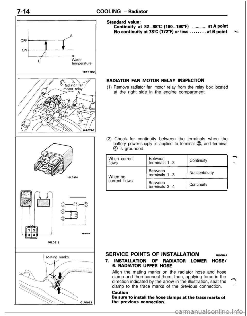
Standard value:Continuity
at 82-88X (180-190°F). . . . . . . . . . .at A pointNo continuity at
78°C (172°F) or less . . . . . . . . at 6 point.r;;;
RADIATOR FAN MOTOR RELAY INSPECTION
(1) Remove radiator fan motor relay from the relay box locatedat the right side in the engine compartment.
16LO312
1Mating marks(2) Check for continuity between the terminals when the
battery power-supply is applied to terminal 0, and terminal
@ is grounded.
When currentBetween
flowsterminals l-3Continuity
When no
current flowsSERVICE POINTS OF
JNSTALLATIONNOMDAF
7. INSTALLATION OF RADIATOR LOWER HOSE/
6. RADIATOR UPPER HOSEAlign the mating marks on the radiator hose and hose
clamp and then connect them; then, applying force in the
direction indicated by the arrow in the illustration, seat the
~
1clamp to the trace marks of the previous connection.Caution
Be sure to install the hose clamps at the trace marks ofthe
previous connection.
Page 263 of 1216
COOLING - Radiator Fan Motor AssemblvIThermostat7-15
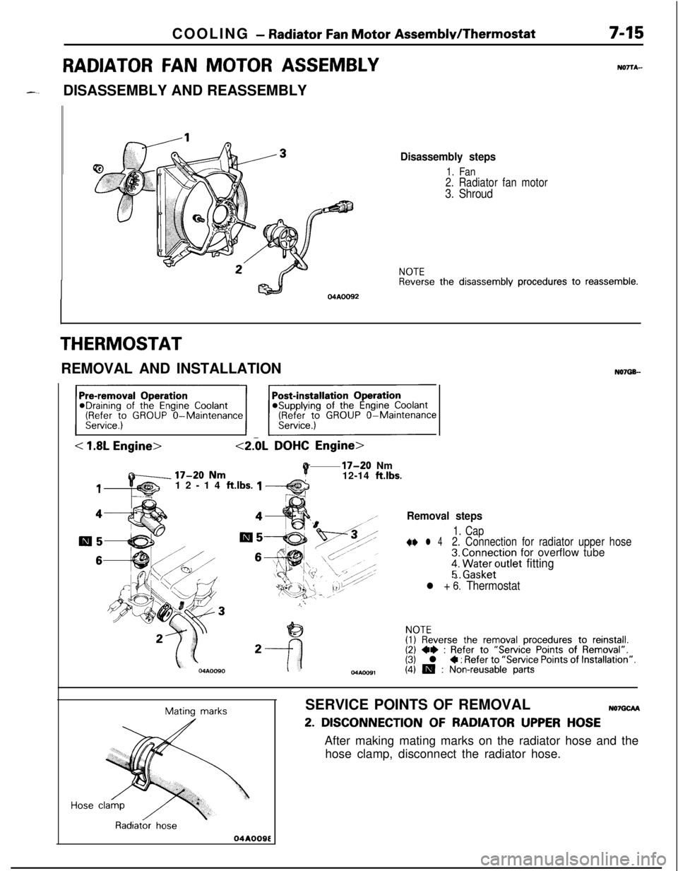
RADIATOR FAN MOTOR ASSEMBLYDISASSEMBLY AND REASSEMBLY
04AOO92
NOTTA-
Disassembly steps
1. Fan2. Radiator fan motor
3. Shroud
NOTEReverse the disassembly procedures to reassemble.
THERMOSTATREMOVAL AND INSTALLATION
N07G6-
< 1.8LDOHC
P17-20 Nm
12-14 ft.lbs.
112-14 ftlbs. 1
44Removal steps
m5al51. Cap+e l 42. Connection for radiator upper hose
663. Connection for overflow tube
;. ra;t;er;utlet fitting
l + 6: Thermostat
NOTE
2(I) Reverse the removal procedures to reinstall.(2) ~~ : Refer to “Service Points of Removal”.(3) l 4 : Refer to “Service Points of Installation”.
04Aoo91(4) 19 : Non-reusable parts
Mating marks
Radiator hose
04A009ESERVICE POINTS OF REMOVAL
NO7GCFU
2. DISCONNECTION OF RADIATOR UPPER HOSEAfter making mating marks on the radiator hose and the
hose clamp, disconnect the radiator hose.
Page 264 of 1216
7-16COOLING - Thermostat
INSPECTIONy+w
l Check that valve closes tightly at room temperature.
l Check for defects or damage.
l Check for rust or encrustation on valve. Remove if any.
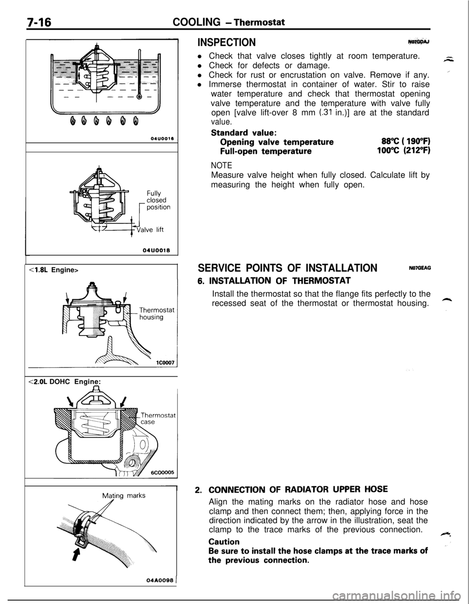
l Immerse thermostat in container of water. Stir to raise
water temperature and check that thermostat opening
valve temperature and the temperature with valve fully
open [valve lift-over 8 mm
(.31 in.)] are at the standard
value.Standard
value:Opening
valve temperature
Full-open temperature
88°C ( 190°F)
100°C (212°F)
Fullyclosedpositionve lift
04UOO18<1.8L Engine><2.0L DOHCEngine:
IMating
marks
NOTEMeasure valve height when fully closed. Calculate lift by
measuring the height when fully open.
SERVICE POINTS OF INSTALLATIONNOlGEAG
6. INSTALLATION OF THERMOSTAT
Install the thermostat so that the flange fits perfectly to the
recessed seat of the thermostat or thermostat housing.
2.CONNECTION OF RADIATOR UPPER HOSEAlign the mating marks on the radiator hose and hose
clamp and then connect them; then, applying force in the
direction indicated by the arrow in the illustration, seat the
clamp to the trace marks of the previous connection.
Caution
Be sure to install the hose clamps at the trace marks ofthe
previous connection.
04A0099 )
Page 274 of 1216
7-26COOLING - Water Hose and Water Pipe <1.8L Engine>
43-55 Nm
31-40 ft.lbs.
lo‘-12 Nm
7-9 ft.lbs.
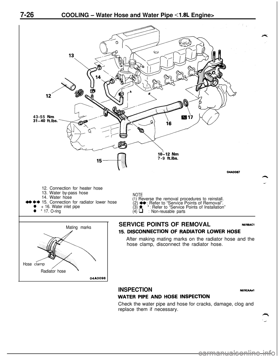
12. Connection for heater hose
13. Water by-pass hose
14. Water hose
++ e+ 15. Connection for radiator lower hosel + 16. Water inlet pipe
l * 17. O-ring
NOTE(1) Reverse the removal procedures to reinstall.(2) +e : Refer to “Service Points of Removal”.(3) l * : Refer to “Service Points of Installation”(4) q : Non-reusable parts
Mating marks
Hose
Radiator hose’
04AOOSSSERVICE POINTS OF REMOVAL
NO7ISACl
15. DISCONNECTION OF RADIATOR LOWER HOSEAfter making mating marks on the radiator hose and the
hose clamp, disconnect the radiator hose.
INSPECTIONNO7KAAaI
WATER PIPE AND HOSE INSPECTIONCheck the water pipe and hose for cracks, damage, clog and
replace them if necessary.
Page 275 of 1216
COOLING - Water Hose and Water Pipe <1.8L Engine>7-27
r
L
0410024
Mating marksSERVICE POINTS OF INSTALLATIONNO7lDAJl
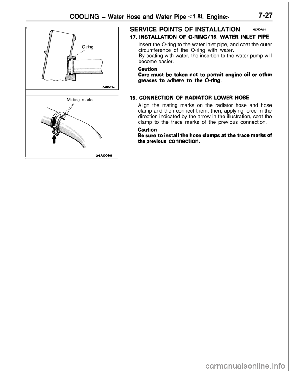
17. INSTALLATION OF 0-l?ING/lG. WATER INLET PIPE
Insert the O-ring to the water inlet pipe, and coat the outer
circumference of the O-ring with water.
By coating with water, the insertion to the water pump will
become easier.
Caution
Care must be taken not to permit engine oil or other
greases to adhere to the O-ring.
15. CONNECTION OF RADIATOR LOWER HOSEAlign the mating marks on the radiator hose and hose
clamp and then connect them; then, applying force in the
direction indicated by the arrow in the illustration, seat the
clamp to the trace marks of the previous connection.
Caution
Be sure to install the hose clamps at the trace marks of
the previous connection.
Page 277 of 1216
,-
COOLING -Water Hose and Water Pipe <2.0L DOHC Engine (Non-Turbo)>7-2943-55 Nm
04A0117
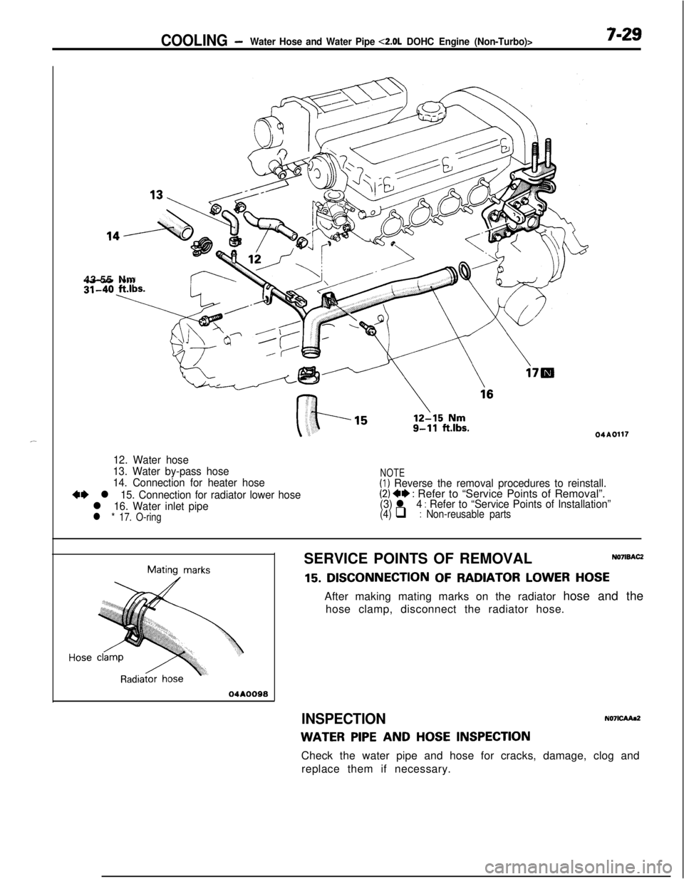
12. Water hose
13. Water by-pass hose
14. Connection for heater hose
+I) l 15. Connection for radiator lower hose
l 16. Water inlet pipel * 17. O-ring
NOTE(1) Reverse the removal procedures to reinstall.(2) 4* : Refer to “Service Points of Removal”.(3) l 4 : Refer to “Service Points of Installation”(4) q : Non-reusable parts
Mating marks
04AOO98SERVICE POINTS OF REMOVAL
NO’IISACZ
15. DISCONNECTION OF RADIATOR LOWER HOSEAfter making mating marks on the radiator hose and the
hose clamp, disconnect the radiator hose.
INSPECTIONN071CAAa2
WATER PIPE AND HOSE INSPECTIONCheck the water pipe and hose for cracks, damage, clog and
replace them if necessary.
Page 278 of 1216
7-30COOLING - waterHose and Water Piue <2.0L DOHC Ermine (Non-Turbo)>
04ROO24
04AOO98SERVICE POINTS OF INSTALLATION
N071DAJZ
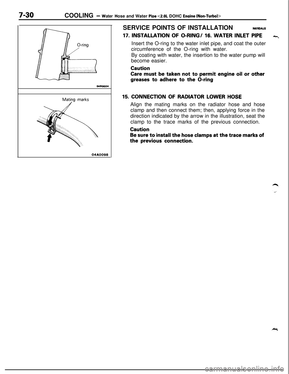
17. INSTALLATION OF O-RING/ 16. WATER INLET PIPE“4Insert the O-ring to the water inlet pipe, and coat the outer
circumference of the O-ring with water.
By coating with water, the insertion to the water pump will
become easier.Caution
Care must be taken not to permit engine oil or other
greases to adhere to the O-ring
15. CONNECTION OF RADIATOR LOWER HOSEAlign the mating marks on the radiator hose and hose
clamp and then connect them; then, applying force in the
direction indicated by the arrow in the illustration, seat the
clamp to the trace marks of the previous connection.Caution
Be sure to install the hose clamps at the trace marks ofthe
previous connection.
Page 280 of 1216
7-32COOLING -Water Hose and Water Pipe <2.0L DOHC Engine (Turbo)>
35-50 Nm/ 25-36 ft.lbs.
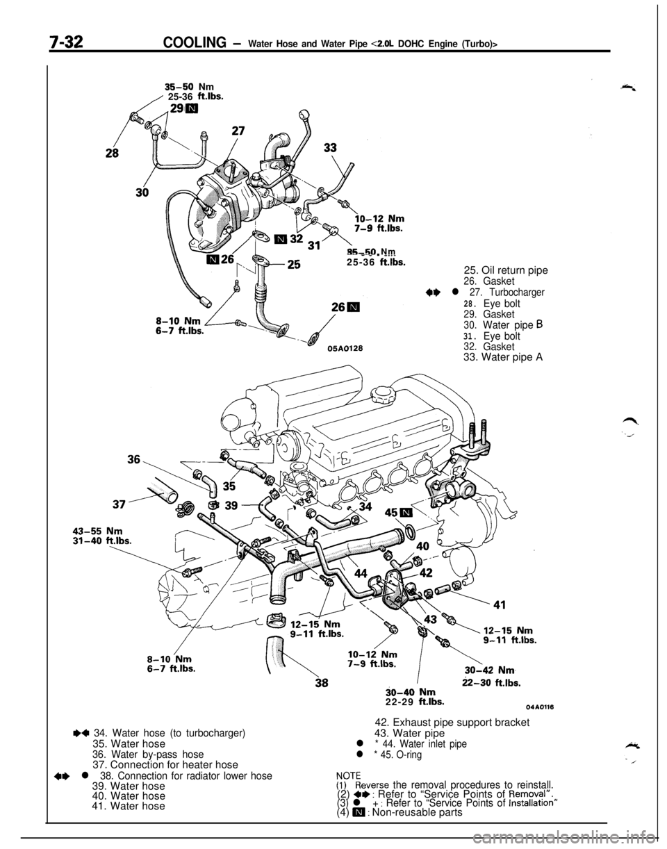
35-50 Nm-- - _ . __._25-36 ft.lbs.25. Oil return pipe
26.Gasket
++ l 27. Turbocharger
28.Eye bolt29.Gasket
30.Water pipe631.Eye bolt32.Gasket33. Water pipe A
++ 34. Water hose (to turbocharger)35. Water hose
36. Water by-pass hose37. Connection for heater hose
+e l 38. Connection for radiator lower hose39. Water hose
40. Water hose
41. Water hose
22-30 ft.lbs.30-40 Nm
22-29 ft.lbs.04A011642. Exhaust pipe support bracket
43. Water pipe
l * 44. Water inlet pipe
l * 45. O-ring
FFTkeverse the removal procedures to reinstall.(2) a+ : Refer to “Service Points of Removal”.(3) l + : Refer to “Service Points of Installation”(4) m : Non-reusable parts
Page 281 of 1216
COOLING- Water Hose and Water Pipe <2.0L DOHC Engine (Turbo)>7-330140552
Mating marks
04A0090
rMating marks
04A0090
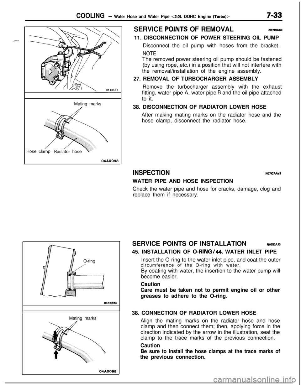
SERVICE POINTS OF REMOVALNO7lBAC311. DISCONNECTION OF POWER STEERING OIL PUMP
Disconnect the oil pump with hoses from the bracket.
NOTEThe removed power steering oil pump should be fastened
(by using rope, etc.) in a position that will not interfere with
the removal/installation of the engine assembly.
27. REMOVAL OF TURBOCHARGER ASSEMBLY
Remove the turbocharger assembly with the exhaust
fitting, water pipe A, water pipe
B and the oil pipe attached
to it.
38. DISCONNECTION OF RADIATOR LOWER HOSE
After making mating marks on the radiator hose and the
hose clamp, disconnect the radiator hose.
INSPECTIONN07lCAAa3WATER PIPE AND HOSE INSPECTION
Check the water pipe and hose for cracks, damage, clog and
replace them if necessary.
SERVICE POINTS OF INSTALLATION
N071DAJ345. INSTALLATION OF
0-RING/44. WATER INLET PIPE
Insert the O-ring to the water inlet pipe, and coat the outer
circumference of the O-ring with water.
By coating with water, the insertion to the water pump will
become easier.
Caution
Care must be taken not to permit engine oil or other
greases to adhere to the O-ring.
38. CONNECTION OF RADIATOR LOWER HOSE
Align the mating marks on the radiator hose and hose
clamp and then connect them; then, applying force in the
direction indicated by the arrow in the illustration, seat the
clamp to the trace marks of the previous connection.
Caution
Be sure to install the hose clamps at the trace marks ofthe previous connection.
Page 315 of 1216
ENGINE <1.8L Engine> - Engine Assembly9-31
ENGINE ASSEMBLY
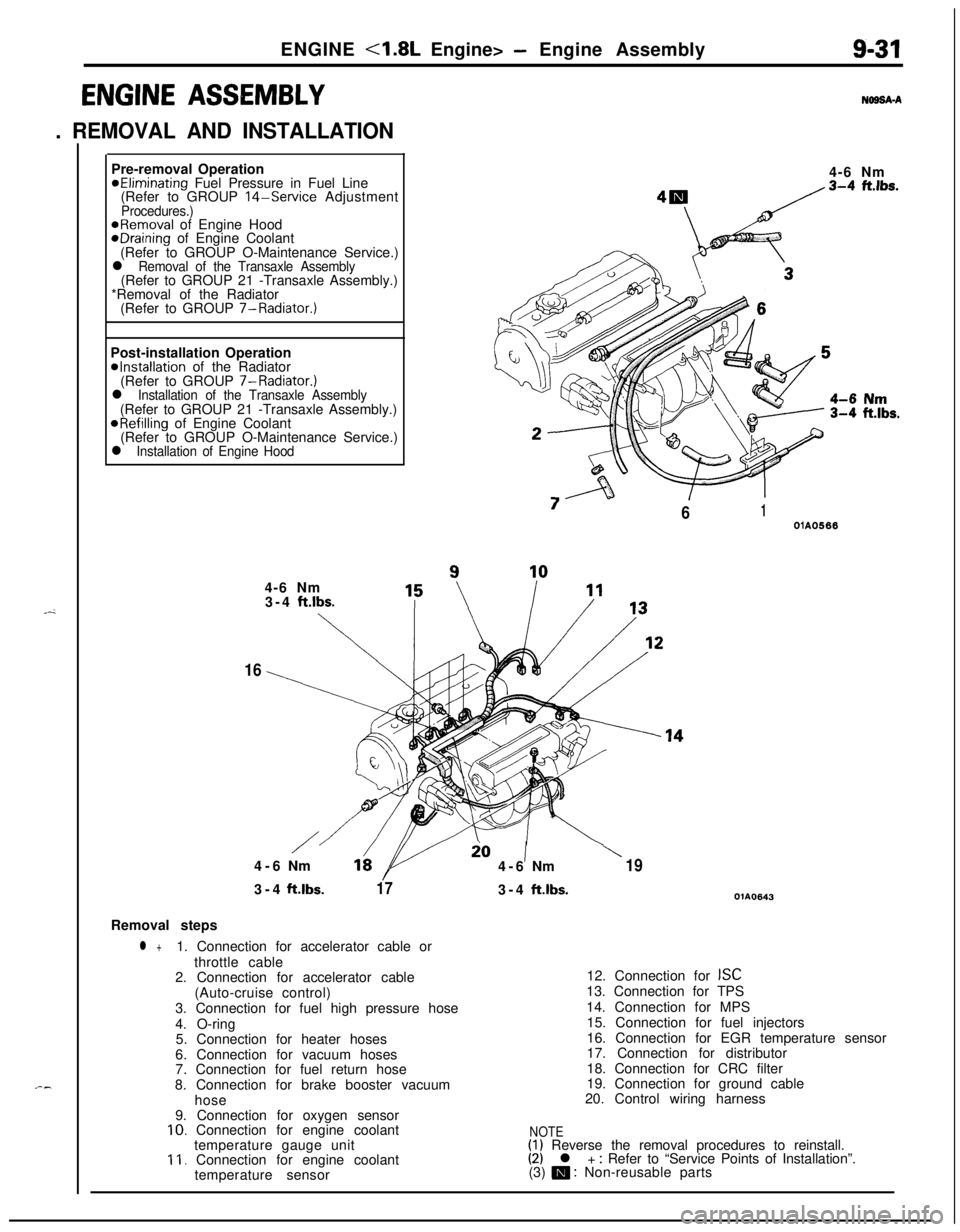
. REMOVAL AND INSTALLATION
N69SA-APre-removal Operation
@Eliminating Fuel Pressure in Fuel Line
(Refer to GROUP 14-Service AdjustmentProcedures.)@Removal of Engine HoodeDraining of Engine Coolant
(Refer to GROUP O-Maintenance Service.)
l Removal of the Transaxle Assembly(Refer to GROUP 21 -Transaxle Assembly.)
*Removal of the Radiator
(Refer to GROUP 7-Radiator.)
Post-installation Operation
@Installation of the Radiator
(Refer to GROUP 7-Radiator.)
l Installation of the Transaxle Assembly(Refer to GROUP 21 -Transaxle Assembly.)
@Refilling of Engine Coolant
(Refer to GROUP O-Maintenance Service.)
l Installation of Engine Hood4-6 Nm
“7
/61OlA05664-6 Nm
3-4
ft.lbs.
\
16
/io1\4-6Nm164-6Nm193-4ft.lbs.
173-4ft.lbs.OlA0643Removal steps
l +1. Connection for accelerator cable or
throttle cable
2. Connection for accelerator cable
(Auto-cruise control)
3. Connection for fuel high pressure hose
4. O-ring
5. Connection for heater hoses
6. Connection for vacuum hoses
7. Connection for fuel return hose
8. Connection for brake booster vacuum
hose
9. Connection for oxygen sensor
10. Connection for engine coolant
temperature gauge unit
11. Connection for engine coolant
temperature sensor12. Connection for
ISC13. Connection for TPS
14. Connection for MPS
15. Connection for fuel injectors
16. Connection for EGR temperature sensor
17. Connection for distributor
18. Connection for CRC filter
19. Connection for ground cable
20. Control wiring harness
NOTE(1) Reverse the removal procedures to reinstall.(2) l + : Refer to “Service Points of Installation”.
(3) m : Non-reusable parts