Table MITSUBISHI ECLIPSE CROSS 2020 Owner's Manual (in English)
[x] Cancel search | Manufacturer: MITSUBISHI, Model Year: 2020, Model line: ECLIPSE CROSS, Model: MITSUBISHI ECLIPSE CROSS 2020Pages: 427, PDF Size: 78.05 MB
Page 4 of 427
Table of contents
123456789101112
Overview Quick indexGeneral information Seat and restraint systems Features and controlsDriving safetyComfort controlsFor emergenciesVehicle care and maintenance Customer assistance/
Reporting Safety Defects
Specifications Alphabetical index
BK0277700US.bo
ok 1 ページ 2019年3月8日 金曜日 午前9時23分
Page 8 of 427
Interior
Overview 1-4
1
N00100302604
Interior
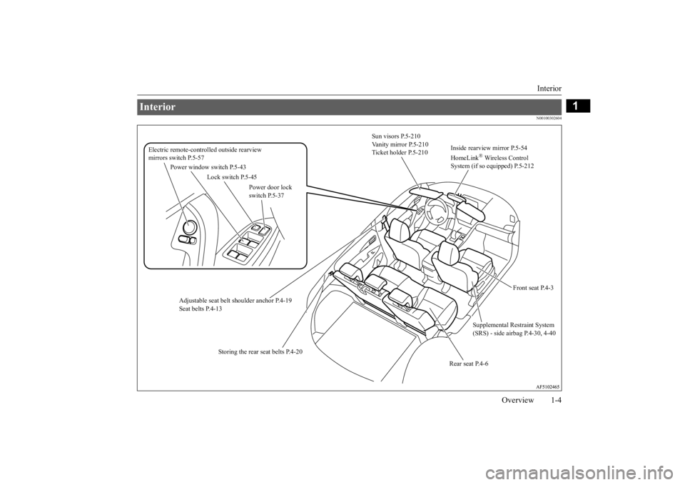
Sun visors P.5-210 Vanity mirror P.5-210 Ticket holder P.5-210
Supplemental Restraint System (SRS) - side airbag P.4-30, 4-40
Adjustable seat belt
shoulder anchor P.4-19
Seat belts P.4-13
Electric remote-controlled outside rearview mirrors switch P.5-57
Lock switch P.5-45
Power door lock switch P.5-37
Power window switch P.5-43
Rear seat P.4-6
Front seat P.4-3
Inside rearview mirror P.5-54 HomeLink
® Wireless Control
System (if so equipped) P.5-212
Storing the rear seat belts P.4-20
BK0277700US.bo
ok 4 ページ 2019年3月8日 金曜日 午前9時23分
Page 24 of 427
Filling the fuel tank
General information 3-3
3
MMT is a manganese-containing metallic additive that is blended into some gasolines to increase the octane number. Mitsubishi Motors Corporation recommends using gaso-lines without MMT. Use of gasolines blended with MMT may adversely affect performance, and cause themalfunction indicator on your instrumentpanel to come on. If this happens, contact an authorized Mitsubishi Motors dealer or a repair facility of your choice for assistance. Your vehicle may have been designed to sat- isfy California’s low-emission regulationsbased on clean-burning low-sulfur gasoline. Gasoline sold in parts of the country other than California is allowed to have a highersulfur content. Using such gasoline could adversely affect the vehicle’s catalytic con- verter and cause the engine malfunction indi-cator (“SERVICE ENGINE SOON” or “Check engine light”) to come on. Illumina- tion of this indicator while using high-sulfurgasoline does not necessarily mean the vehi- cle’s emission-control system is malfunction- ing. Your authorized Mitsubishi Motors
dealer may suggest using a different, lower- sulfur brand of unleaded gasoline to deter- mine if the problem is fuel-related.
N00301102018
MMT (methylcyclopentadienyl manganese tricarbonyl) Sulfur in gasoline
NOTE
Poor-quality gasoline can cause problems such as hard starting, stalling during idling, abnormal engine noise, and poor accelera- tion. If you experience any of these prob-lems, try using a different brand of gasoline. If the engine malfunction indicator (“SER- VICE ENGINE SOON” or “Check enginelight”) flashes, have the vehicle inspected as soon as possible by the nearest authorized Mitsubishi Motors dealer or a repair facilityof your choice. Repeatedly driving short distances at low speeds can cause deposits to form in the fuel system and engine, resulting in hard starting and poor acceleration. If these problemsoccur, you are advised to add a detergent additive to the gasoline when you refuel the vehicle. The additive will remove the depos-its, thereby returning the engine to a normal condition. Be sure to use a Mitsubishi Motors Genuine cleaning additive. Using anunsuitable additive could make an engine malfunction. For details, please contact the nearest authorized Mitsubishi Motors dealer.
Filling the fuel tank
WA R N I N G When handling fuel, comply with the safety regulations displayed by garages and filling stations. Gasoline is highly flammable and explo- sive. You could be burned, seriously injured or killed when handling it. Whenrefueling your vehicle, always turn the engine off and keep away from flames, sparks, and smoking materials. Alwayshandle fuel in well-ventilated outdoor areas. Before removing the fuel tank filler cap, be sure to get rid of your body’s static electricity by touching a metal part of thevehicle or fuel pump. Any static electricity on your body could create a spark that ignites fuel vapor. Perform the whole refueling process (opening the fuel tank filler door, remov-ing the fuel cap, etc.) by yourself; do not let any other person near the fuel tank filler. If you allowed a person to help youand that person was carrying static elec- tricity, fuel vapor could be ignited. Do not move away from the fuel tank filler until refueling is finished. If you movedaway and did something else (for example, sitting on a seat) part-way through the refueling process, you could pick up afresh charge of static electricity.
BK0277700US.bo
ok 3 ページ 2019年3月8日 金曜日 午前9時23分
Page 40 of 427
Front seats
Seat and restraint systems 4-5
4
N00402001441
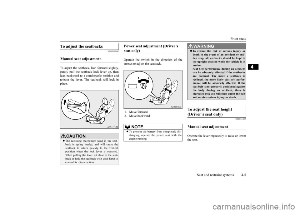
To adjust the seatback, lean forward slightly, gently pull the seatb
ack lock lever up, then
lean backward to a comfortable position and release the lever. The seatback will lock in place.
Operate the switch in the direction of the arrows to adjust the seatback.
N00402101295
Operate the lever repeatedly to raise or lowerthe seat.
To adjust the seatbacks Manual seat adjustment
CAUTION The reclining mechanism used in the seat- back is spring loaded
, and will cause the
seatback to return quickly to the vertical position when the lock lever is operated.When pulling the lever, sit close to the seat- back or hold the seatback with your hand to control its return motion.
Power seat adjustment (Driver’s seat only) 1- Move forward 2- Move backward
NOTE
To prevent the battery from completely dis- charging, operate the power seat with the engine running.
WA R N I N G To reduce the risk of serious injury or death in the event of an accident or sud- den stop, all seatbacks should be kept in the upright position while the vehicle is in motion.Seat belt performance during an accident can be adversely affected if the seatbacks are reclined. The more a seatback isreclined, the more likely seat belt perfor- mance will be adversely affected. If the seat belt is not properly positioned againstthe body during an accident, there is increased risk you will slide under the belt and receive serious injury or death.
To adjust the seat height (Driver’s seat only) Manual seat adjustment
BK0277700US.bo
ok 5 ページ 2019年3月8日 金曜日 午前9時23分
Page 54 of 427
Seat belts
Seat and restraint systems 4-19
4
If the ignition switch is turned to the “ON” position or the operation mode is put in ON without the driver’s seat belt being fastened, a warning light will come on and a tone willsound for approximately 6 seconds to remind you to fasten your seat belt. If the vehicle is driven with the seat belt stillunfastened, the warning light will blink and the tone will sound intermittently until the seat belt is fastened. At the same time, “FAS-TEN SEAT BELT” is displayed on the infor-mation screen in the multi-information display.
N00418301276
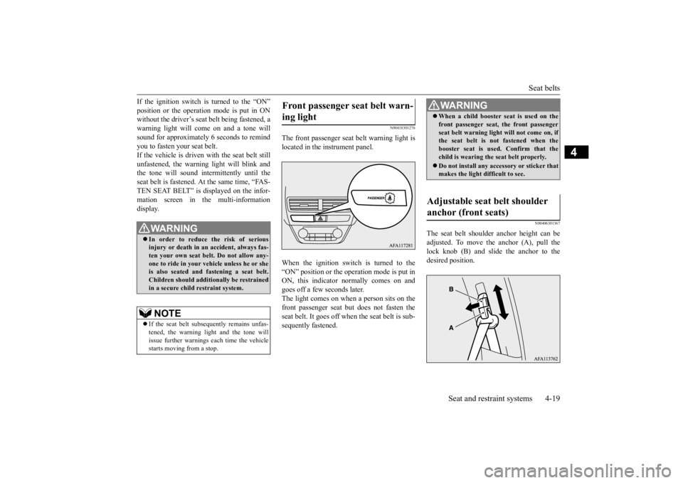
The front passenger seat belt warning light is located in the instrument panel. When the ignition switch is turned to the “ON” position or the operation mode is put inON, this indicator normally comes on and goes off a few seconds later. The light comes on when a person sits on thefront passenger seat but does not fasten the seat belt. It goes off when the seat belt is sub- sequently fastened.
N00406301367
The seat belt shoulder anchor height can beadjusted. To move the anchor (A), pull the lock knob (B) and slide the anchor to the desired position.
WA R N I N G In order to reduce the risk of serious injury or death in an accident, always fas-ten your own seat belt. Do not allow any- one to ride in your vehicle unless he or she is also seated and fastening a seat belt.Children should additionally be restrained in a secure child restraint system.NOTE
If the seat belt subsequently remains unfas- tened, the warning light and the tone will issue further warnings each time the vehiclestarts moving from a stop.
Front passenger seat belt warn- ing light
WA R N I N G When a child booster seat is used on the front passenger seat, the front passenger seat belt warning light will not come on, if the seat belt is not fastened when the booster seat is used. Confirm that thechild is wearing the seat belt properly. Do not install any accessory or sticker that makes the light difficult to see.
Adjustable seat belt shoulder anchor (front seats)
BK0277700US.bo
ok 19 ページ 2019年3月8日 金曜日 午前9時23分
Page 58 of 427
Child restraint systems
Seat and restraint systems 4-23
4
Children who weigh more than 40 pounds (18 kg) or who are more than 40 inches (100 cm) tall, regardless of age, should use a suitable child seat or a booster seatin the rear seat until the vehicle’s lap-and- shoulder belt fits them properly.WA R N I N G All children must be seated in the rear seat, and properly restrained. Accident statistics show that children of all sizes and ages are safer when properlyrestrained in the rear seat, rather than in the front seat. Be sure to select a child restraint system that is appropriate not only for the child’s size and age but also for your vehicle.Some child restraint systems may not fit your vehicle properly.
Any child who is too large to use a child restraint system should ride in the rear seat and wear the lap-and-shoulder belt properly. The shoulder belt must be posi- tioned over the shoulder and across thechest, not across their neck, and with the lap belt positioned low on the child’s hips, not across their stomach. If necessary, abooster seat should be used to help achieve a proper seat belt fit. Follow the booster seat manufacturer’s instructions. Only usea booster seat that is certified as comply- ing with Federal Motor Vehicle Safety Standards or Motor Vehicle Restraint Sys-tems and Booster Seats Safety Regula- tions. WA R N I N G
WA R N I N G Never hold an infant or child in your arms or on your lap when riding in this vehicle, even when you are wearing your seat belt. Never place any part of the seat belt you are wearing around an infant or child.Failure to follow these simple instructions creates a risk of serious injury or death to your child in the event of an accident orsudden stop.
BK0277700US.bo
ok 23 ページ 2019年3月8日 金曜日 午前9時23分
Page 61 of 427
Child restraint systems 4-26 Seat and restraint systems
4
N00419001212
N00419101314
1. In order to securely fasten the tether strap, remove the head restraint from the loca-tion where you wish to install the child restraint system. Refer to “Head restraints” on page 4-9.2. Adjust the rear seat to its most rearward position. Refer to “Rear seats” on page 4-6.3. Push the anchor connectors (A) on the child restraint system into the lower anchors (B) in accordance with theinstructions provided by the child restraint system’s manufacturer. Remember, the lower anchors (B) pro-vided with your vehicle are designed to secure suitable child restraint systems compatible with the LATCH system inthe outboard positions of the rear seats only. The anchor connectors are NOT designed to secure a suitable childrestraint system in the center seating position of the rear seat.
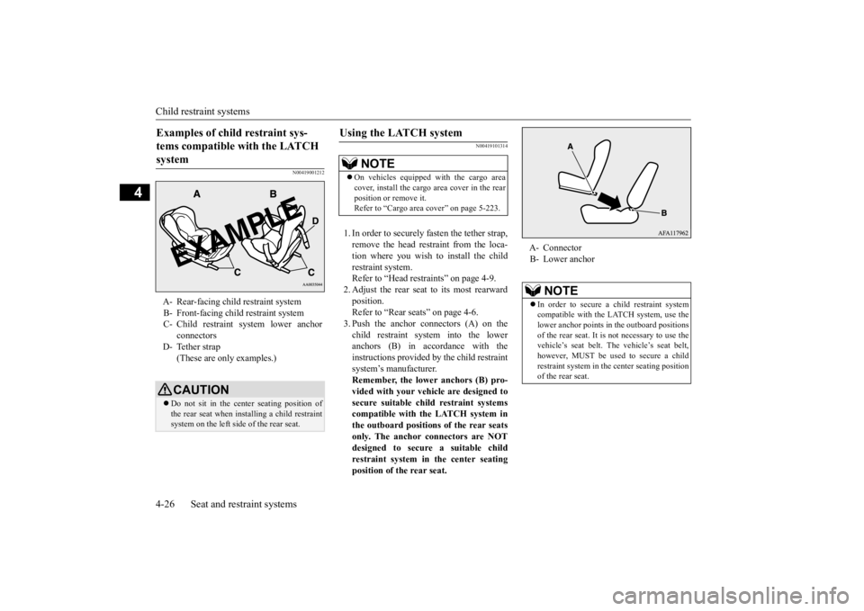
Examples of child restraint sys- tems compatible with the LATCH system A- Rear-facing child restraint system B- Front-facing child restraint systemC- Child restraint system lower anchor
connectors
D- Tether strap
(These are only examples.)CAUTION Do not sit in the center seating position of the rear seat when installing a child restraint system on the left side of the rear seat.
Using the LATCH system
NOTE
On vehicles equipped with the cargo area cover, install the cargo area cover in the rear position or remove it. Refer to “Cargo area cover” on page 5-223.
A- Connector B- Lower anchor
NOTE
In order to secure a child restraint system compatible with the LATCH system, use the lower anchor points in the outboard positions of the rear seat. It is not necessary to use thevehicle’s seat belt. The vehicle’s seat belt, however, MUST be used to secure a child restraint system in the center seating positionof the rear seat.
BK0277700US.bo
ok 26 ページ 2019年3月8日 金曜日 午前9時23分
Page 96 of 427
Free-hand Advanced Security Transmit
ter (F.A.S.T.-key) (if so equipped)
Features and controls 5-15
5
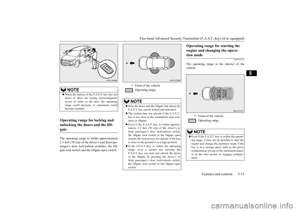
The operating range is within approximately 2.3 feet (70 cm) of the driver’s and front pas- senger’s door lock/unlock switches, the lift- gate lock switch and the liftgate open switch.
N00503301107
The operating range is the interior of thevehicle.
NOTE
When the battery of the F.A.S.T.-key has run down or there are strong electromagnetic waves or noise in the area, the operating range could decrease or operations couldbecome unstable.
Operating range for locking and unlocking the doors and the lift- gate
* : Front of the vehicle : Operating range
NOTE
Only the doors and the liftgate that detect the F.A.S.T.-key can be locked and unlocked. The system may not operate if the F.A.S.T.- key is too close to the windshield, door win- dows or liftgate. Even if the F.A.S.T.-k
ey is within approxi-
mately 2.3 feet (70 cm) of the driver’s or front passenger’s door lock/unlock switch,the liftgate lock switch or the liftgate open switch, the system may not operate if the key is close to the ground or in a high position. If the F.A.S.T.-key is within the operating range, even a person not carrying theF.A.S.T.-key can lock and unlock the doors or the liftgate by pressing the driver’s or front passenger’s door lock/unlock switch,the liftgate lock switch or the liftgate open switch.
Operating range for starting the engine and changing the opera- tion mode
* : Front of the vehicle : Operating range
NOTE
Even if the F.A.S.T.-key is within the operat- ing range, it may not be possible to start theengine and change the operation mode if the key is in a storage space such as the glove compartment, on top of
the instrument panel,
or in the door pocket or luggage compart- ment.
BK0277700US.bo
ok 15 ページ 2019年3月8日 金曜日 午前9時23分
Page 134 of 427

Steering wheel height and reach adjustment
Features and controls 5-53
5
Warning light Warning display If there is a malfunction in the system, the warning light will come on. In addition, thewarning display appears on the information screen in the multi-information display.
Under normal conditions, the warning light only comes on when the ignition switch is turned to the “ON” position or the operation mode is put in ON and goes off a few secondslater.
N00511501241
To adjust the steering wheel to the desiredposition, move the lever upward or down-
If the acceleration of the vehicle seems abnormally slow after the vehicle has been parked with the Electric parking brake applied in cold weather, stop the vehicle in a safe place, then apply and release the Elec-tric parking brake. If the vehicle acceleration is still slow, contact the nearest authorized Mitsubishi Motors dealer or a repair facilityof your choice.NOTE
When the ignition switch or the operation mode is other than ON, the parking brake cannot be released. If the Electric parking brake does not auto- matically release, it may be released by man-ual operation. When the selector lever is other than “P” (PARK) position, if you try to release the Electric parking brake without depressing the brake pedal, the warning display willappear.CAUTION
If you start driving without releasing the Electric parking brake, the warning display will appear. If the driver’s foot contacts the accelerator pedal in the condition that the Electric park-ing brake can release by an automatic opera- tion, the Electric parking brake may be released automatically.
Warning light/display
NOTE
CAUTION When the Electric parking brake warning light does not illuminate or remains illumi- nated when the ignition switch is turned tothe “ON” position or the operation mode is put in ON, or comes on while driving, the Electric parking brake may not be applied orreleased. Immediately contact the nearest authorized Mitsubishi Motors dealer or a repair facilityof your choice. For details, refer to “Electric parking brake warning light” on page 5-184. When parking your vehicle while the Elec-tric parking brake warning light is illumi- nated, park the vehicle on level and stable ground, move the selector lever to the “P”(PARK) position and place chocks, blocks, stones behind and in front of the tires to pre- vent the vehicle from moving.
Steering wheel height and reach adjustment
BK0277700US.bo
ok 53 ページ 2019年3月8日 金曜日 午前9時23分
Page 151 of 427
S-AWC (Super-All Wheel Control) (if so equipped) 5-70 Features and controls
5
N00541301118
S-AWC is an integrated vehicle dynamics control system that helps enhance driving performance, cornering performance, and vehicle stability over a wide range of drivingconditions through integrated management of the electronically controlled 4WD, the AYC, the ABS and the ASC. The electronically controlled 4WD is a sys- tem that improves acceleration performance and stability performance by controllingfront-rear distribution of driving torque with
operating the electronic control coupling arranged in the rear differential assembly. Refer to “Active Yaw Control (AYC)” on page 5-81.
N00542401116
Select the drive mode from the followingthree types to suit the driving conditions.
4-wheel drive operation requires special driv- ing skills.Carefully read the “4-wheel drive operation”section on page 5-72
and take care to drive
safety.
S-AWC (Super-All Wheel Control)
(if so equipped)
CAUTION Do not over-rely on the S-AWC. Even the S- AWC cannot prevent the natural laws ofphysics from acting on the vehicle. This sys- tem, like any other system, has limits and cannot help you to maintain traction and con-trol of the vehicle in all circumstances. Reck- less driving can lead to accidents. It is the driver’s responsibility to drive carefully.This means taking into account the traffic, road and environmental conditions.
Electronically Controlled 4WD
NOTE
On vehicles equipped with lever type park- ing brake, if the parking brake lever is pulled up while the vehicle is moving, the front-reardistribution of driving torque control will be temporarily suspended, which will allow the rear wheel to lock easier.
Active Yaw Control (AYC)
S-AWC drive mode
S-AWC drive mode
Function
AUTO
This mode can be used on both dry and wet roads. The distri- bution of driving/braking torque to each wheel is auto- matically controlled according to the driving condition.
SNOW
This mode is for driving on slippery road surfaces, such as snow-covered roads.
GRAVEL
This mode is suitable mainly for driving on unpaved or rough roads. This mode provides 4WD high driving performance and stable cornering performance.
S-AWC drive mode
Function
BK0277700US.bo
ok 70 ページ 2019年3月8日 金曜日 午前9時23分