Abs sensor MITSUBISHI ENDEAVOR 2004 Service Owners Manual
[x] Cancel search | Manufacturer: MITSUBISHI, Model Year: 2004, Model line: ENDEAVOR, Model: MITSUBISHI ENDEAVOR 2004Pages: 3870, PDF Size: 98.47 MB
Page 3204 of 3870
Q: Is the ABS sensor in good condition?
YES: Go to Step 6.
NO: Replace the ABS sensor. Then go to Step 16.
STEP 6. Check the wheel bearing for looseness.
DTC C1201 is set: Check the front right wheel bearing (Refer toWHEEL BEARING END PLAY CHECK
).
DTC C1206 is set: Check the front left wheel bearing (Refer to WHEEL BEARING END PLAY CHECK
).
DTC C1211 is set: Check the rear right wheel bearing (Refer to WHEEL BEARING END PLAY CHECK
).
DTC C1216 is set: Check the rear left wheel bearing (Refer to WHEEL BEARING END PLAY CHECK
).
Q: Is the wheel bearing end play within the standard value?
YES: Go to Step 7.
NO (front bearing end play is not within the standard value): Replace
the front hub assembly (Refer to FRONT AXLE HUB ASSEMBLY
, ).
Then go to Step 16.
NO (rear bearing end play is not within the standard value): Replace
the rear hub assembly (Refer to REAR AXLE
). Then go to Step 16.
STEP 7. Check the ABS rotor.
Check the ABS rotor, which DTC code indicates, for foreign material or
deformation.
DTC C1201 is set: Front right ABS sensor DTC C1206 is set: Front left ABS sensor
NOTE: If the wheel bearing is loose, the gap between the ABS
sensor and rotor may become excessive. Check the
wheel bearing, which DTC code indicates, for
looseness.
2004 Mitsubishi Endeavor LS
2004 BRAKES Traction Control, Active Skid Control System - Endeavor
Page 3205 of 3870
DTC C1211 is set: Rear right ABS sensor DTC C1216 is set: Rear left ABS sensor
Q: Is the ABS rotor in good condition?
YES: Go to Step 8.
NO (front bearing end play is not within the standard value): If the
ABS rotor is contaminated with foreign material, clean it. If the driveshaft
is deformed, replace it (Refer to DRIVE SHAFT ASSEMBLY
, ). Then
go to Step 16.
NO (rear bearing end play is not within the standard value): If the
ABS rotor is contaminated with foreign material, clean it. If the BJ
assembly is deformed, replace it (Refer to DRIVE SHAFT
ASSEMBLY
). Then go to Step 16.
STEP 8. Measure the voltage at TCL/ASC-ECU connector A-32.
1. Disconnect the connector A-32, and connect special tool ABS Check
Harness (MB991952) to the wiring harness-side connector.
2. Turn the ignition switch to the "ON" position.
3. Measure the voltage between the relevant signal and ground terminals in
the ABS sensor circuit and body ground. It should be less than 1V.
DTC C1201 is set: Between signal terminal 30 and body ground, and
between ground terminal 21 and body ground DTC C1206 is set: Between signal terminal 22 and body ground, and
between ground terminal 31 and body ground DTC C1211 is set: Between signal terminal 8 and body ground, and
between ground terminal 9 and body ground DTC C1216 is set: Between signal terminal 6 and body ground, and between
ground terminal 7 and bod
y ground
NOTE: Do not connect special tool ABS Check Harness
(MB991952) to the TCL/ASC-ECU.
2004 Mitsubishi Endeavor LS
2004 BRAKES Traction Control, Active Skid Control System - Endeavor
Page 3207 of 3870
Q: Does the voltage measure 1 V or less?
YES: Go to Step 9.
NO (When the voltage between terminal 30 or 21 - and body ground
measures more than 1 V): Go to Step 11.
NO (When the voltage between terminal 22 or 31 - and body ground
measures more than 1 V): Go to Step 12.
NO (When the voltage between terminal 8 or 9 - and body ground
measures more than 1 V): Go to Step 13.
NO (When the voltage between terminal 6 or 7 - and body ground
measures more than 1 V): Go to Step 14.
STEP 9. Measure the resistance at TCL/ASC-ECU connector A-32.
1. Disconnect the connector A-32, and connect special tool ABS Check
Harness (MB991952) to the wiring harness-side connector.
2. Measure the resistance between the relevant signal and ground terminals
in the ABS sensor circuit and body ground. OK if there is no continuity.
DTC C1201 is set: Between signal terminal 30 and body ground, and
between ground terminal 21 and body ground DTC C1206 is set: Between signal terminal 22 and body ground, and
between ground terminal 31 and body ground DTC C1211 is set: Between signal terminal 8 and body ground, and
between ground terminal 9 and body ground DTC C1216 is set: Between signal terminal 6 and body ground, and between ground terminal 7 and body ground
NOTE: Do not connect special tool ABS Check Harness
(MB991952) to the TCL/ASC-ECU.
2004 Mitsubishi Endeavor LS
2004 BRAKES Traction Control, Active Skid Control System - Endeavor
Page 3209 of 3870
Q: Does continuity exist?
YES (Continuity exists between terminal 30 or terminal 21 and body
ground): Go to Step 11.
YES (Continuity exists between terminal 22 or terminal 31 and body
ground): Go to Step 12.
YES (Continuity exists between terminal 8 or terminal 9 and body
ground): Go to Step 13.
YES (Continuity exists between terminal 6 or terminal 7 and body
ground): Go to Step 14.
NO: Go to Step 10.
STEP 10. Measure the resistance at TCL/ASC-ECU connector A-32.
1. Disconnect the connector A-32, and connect special tool ABS Check
Harness (MB991952) to the wiring harness-side connector.
2. Measure the resistance between the relevant signal and ground terminals
in the ABS sensor circuit.
DTC C1201 is set: Between signal terminal 30 and ground terminal
21 DTC C1206 is set: Between signal terminal 22 and ground terminal
31 DTC C1211 is set: Between signal terminal 8 and ground terminal 9 DTC C1216 is set: Between signal terminal 6 and ground terminal 7
Standard Value: 1.24 - 1.64 kohm
NOTE: Do not connect special tool ABS Check Harness
(MB991952) to the TCL/ASC-ECU.
2004 Mitsubishi Endeavor LS
2004 BRAKES Traction Control, Active Skid Control System - Endeavor
Page 3211 of 3870

Q: Is the resistance between terminals 30 and 21, 22 and 31, 8 and 9, or 6
and 7 within the standard value?
YES (When resistances between all terminals are within the standard
value): Go to Step 15.
NO (When resistance between terminals 30 and 21 is not within the
standard value): Go to Step 11.
NO (When resistance between terminals 22 and 31 is not within the
standard value): Go to Step 12.
NO (When resistance between terminals 8 and 9 is not within the
standard value): Go to Step 13.
NO (When resistance between terminals 6 and 7 is not within the
standard value): Go to Step 14.
STEP 11. Check TCL/ASC-ECU connector A-32 and ABS sensor < front:
RH > connector A-31 for loose, corroded or damaged terminals, or
terminals pushed back in the connector.
2004 Mitsubishi Endeavor LS
2004 BRAKES Traction Control, Active Skid Control System - Endeavor
Page 3213 of 3870
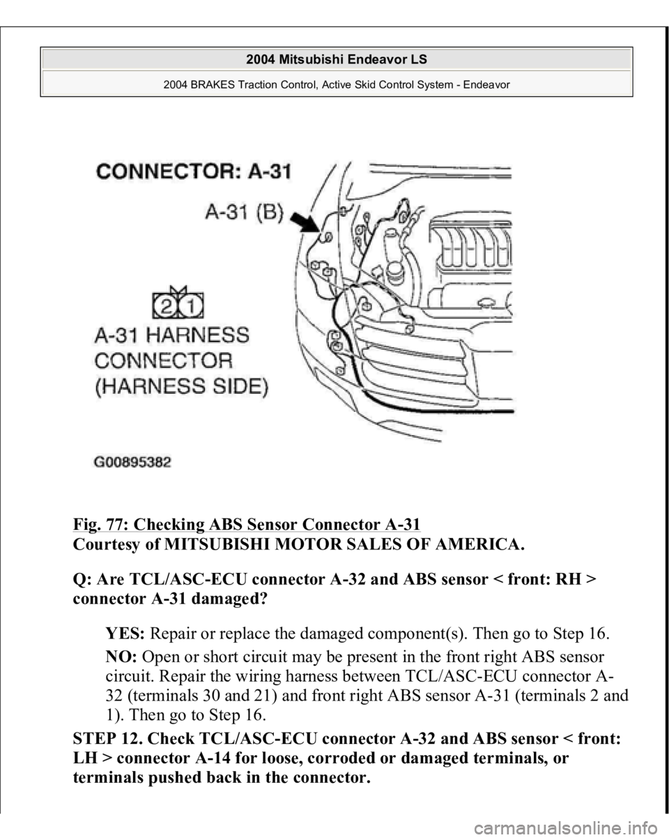
Fig. 77: Checking ABS Sensor Connector A
-31
Courtesy of MITSUBISHI MOTOR SALES OF AMERICA.
Q: Are TCL/ASC-ECU connector A-32 and ABS sensor < front: RH >
connector A-31 damaged?
YES: Repair or replace the damaged component(s). Then go to Step 16.
NO: Open or short circuit may be present in the front right ABS sensor
circuit. Repair the wiring harness between TCL/ASC-ECU connector A-
32 (terminals 30 and 21) and front right ABS sensor A-31 (terminals 2 and
1). Then go to Step 16.
STEP 12. Check TCL/ASC-ECU connector A-32 and ABS sensor < front:
LH > connector A-14 for loose, corroded or damaged terminals, or
terminals pushed back in the connector.
2004 Mitsubishi Endeavor LS
2004 BRAKES Traction Control, Active Skid Control System - Endeavor
Page 3215 of 3870
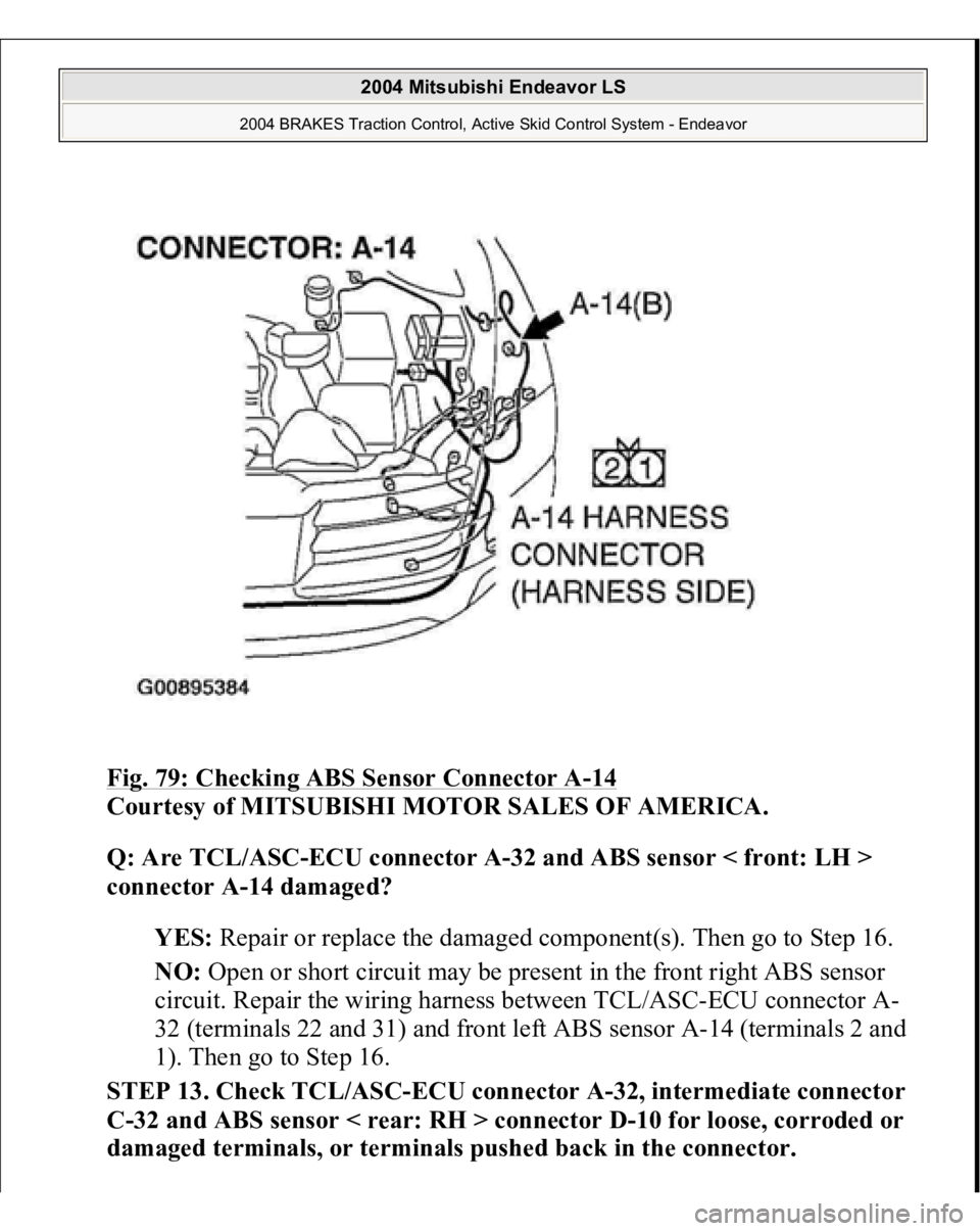
Fig. 79: Checking ABS Sensor Connector A
-14
Courtesy of MITSUBISHI MOTOR SALES OF AMERICA.
Q: Are TCL/ASC-ECU connector A-32 and ABS sensor < front: LH >
connector A-14 damaged?
YES: Repair or replace the damaged component(s). Then go to Step 16.
NO: Open or short circuit may be present in the front right ABS sensor
circuit. Repair the wiring harness between TCL/ASC-ECU connector A-
32 (terminals 22 and 31) and front left ABS sensor A-14 (terminals 2 and
1). Then go to Step 16.
STEP 13. Check TCL/ASC-ECU connector A-32, intermediate connector
C-32 and ABS sensor < rear: RH > connector D-10 for loose, corroded or
damaged terminals, or terminals pushed back in the connector.
2004 Mitsubishi Endeavor LS
2004 BRAKES Traction Control, Active Skid Control System - Endeavor
Page 3218 of 3870
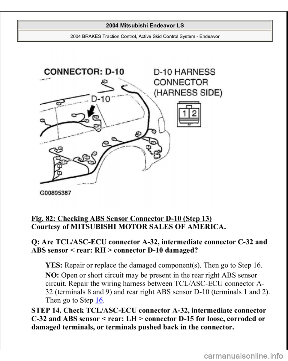
Fig. 82: Checking ABS Sensor Connector D
-10 (Step 13)
Courtesy of MITSUBISHI MOTOR SALES OF AMERICA.
Q: Are TCL/ASC-ECU connector A-32, intermediate connector C-32 and
ABS sensor < rear: RH > connector D-10 damaged?
YES: Repair or replace the damaged component(s). Then go to Step 16.
NO: Open or short circuit may be present in the rear right ABS sensor
circuit. Repair the wiring harness between TCL/ASC-ECU connector A-
32 (terminals 8 and 9) and rear right ABS sensor D-10 (terminals 1 and 2).
Then go to Step 16
.
STEP 14. Check TCL/ASC-ECU connector A-32, intermediate connector
C-32 and ABS sensor < rear: LH > connector D-15 for loose, corroded or
damaged terminals, or terminals pushed back in the connector.
2004 Mitsubishi Endeavor LS
2004 BRAKES Traction Control, Active Skid Control System - Endeavor
Page 3221 of 3870
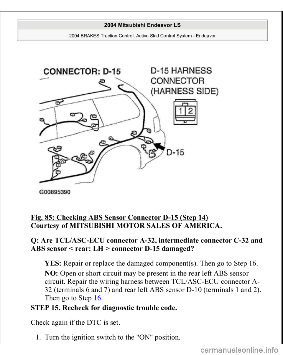
Fig. 85: Checking ABS Sensor Connector D
-15 (Step 14)
Courtesy of MITSUBISHI MOTOR SALES OF AMERICA.
Q: Are TCL/ASC-ECU connector A-32, intermediate connector C-32 and
ABS sensor < rear: LH > connector D-15 damaged?
YES: Repair or replace the damaged component(s). Then go to Step 16.
NO: Open or short circuit may be present in the rear left ABS sensor
circuit. Repair the wiring harness between TCL/ASC-ECU connector A-
32 (terminals 6 and 7) and rear left ABS sensor D-10 (terminals 1 and 2).
Then go to Step 16
.
STEP 15. Recheck for diagnostic trouble code.
Check again if the DTC is set.
1. Turn the ignition switch to the "ON" position.
2004 Mitsubishi Endeavor LS
2004 BRAKES Traction Control, Active Skid Control System - Endeavor
Page 3419 of 3870
2. Turn the ignition switch to "ON" position.
3. Diagnose the CAN bus line.
Q: Is the check result satisfactory?
YES: Go to Step 2
NO: Repair the CAN bus lines (Refer to DIAGNOSTIC TROUBLE
CODE DIAGNOSIS
or DIAGNOSIS < VEHICLES WITHOUT
ADVANCED AIR BAG
). On completion, go to Step 6.
STEP 2. Using scan tool MB991958, read the steering wheel sensor
diagnostic trouble code.
Check if a steering wheel sensor DTC is set.
Q: Is the DTC set?
YES: Diagnose the steering wheel sensor by referring to DIAGNOSTIC
TROUBLE CODE CHART
.
NO: Go to Step 3.
STEP 3. Using scan tool MB991958 read any of the diagnostic trouble
code.
Check if a DTC, which relates to CAN communication-linked systems below,
is set.
Power train control module
DTC U1100: ABS-ECU time-out
Combination meter DTC 011: ABS-ECU time-out
Q: Is the DTC set?
YES: Go to Step 4. NO:
Go to Step
5.
2004 Mitsubishi Endeavor LS
2004 BRAKES Traction Control, Active Skid Control System - Endeavor