Abs sensor MITSUBISHI ENDEAVOR 2004 Service Manual PDF
[x] Cancel search | Manufacturer: MITSUBISHI, Model Year: 2004, Model line: ENDEAVOR, Model: MITSUBISHI ENDEAVOR 2004Pages: 3870, PDF Size: 98.47 MB
Page 3117 of 3870
The ECU incorporates the ABS-ECU, active skid control-ECU, and traction
control-ECU. The integral design allows joint operation of the TCL/ASC-ECU with
the ABS and coordinated control of the driving force and braking force. SYSTEM CONFIGURATION The Traction Control and Active Skid Control (TCL/ASC) System is a system that
adds a yaw rate sensor, a steering wheel sensor and master cylinder pressure sensor
(incorporated in hydraulic unit) to the ABS system. OVERVIEW OF CONTROL The TCL/ASC-ECU detects vehicle movement based on information from various
sensors and calculates a model of ideal vehicle movement. After comparing actual
and ideal movements, it acts to bring the actual vehicle movement closer to the
ideal model by controlling specific wheel brake force and governing engine output.
It restrains under-steering and over-steering through a corrective yaw moment, as
explained on the following pages. EXAMPLE OF ACTIVE SKID CONTROL OPERATION The Active Skid Control manages the vehicle attitude by creating a yaw moment
from altering the balance between the cornering force and each wheel's braking
mechanism.
For example, on a slippery surface, if the vehicle tends to be under-steered contrary
to the driver's intention, a yaw moment (a rotational moment) is created to restrain
the under-steering by increasing the rear-inside braking force. On the other hand,
when the vehicle tends to be over-steered, a yaw moment (a restorative moment) is
created to restrain the over-steering by increasing the front-outside braking force.
Furthermore, when it is determined that the vehicle is over-speeding, safe and stable
cornerin
g is enabled b
y deceleration from restrictin
g en
gine out
put.
2004 Mitsubishi Endeavor LS
2004 BRAKES Traction Control, Active Skid Control System - Endeavor
Page 3120 of 3870
Fig. 10: Identifying Joint Control Specification
s
Courtesy of MITSUBISHI MOTOR SALES OF AMERICA.
EXAMPLE OF OPERATION OF TRACTION CONTROL The Traction Control prevents drive force loss during slipping of the drive wheels
by automatically applying the brakes and sending engine torque reduction signal to
the PCM when the drive wheels slip or when driving on partly low-friction
surfaces. FAIL-SAFE AND DIAGNOSTIC FUNCTIONS The TCL/ASC-ECU regularly monitors input and out put signals. If an error is
detected in the system, the ECU sends a fail signal and the TCL/ASC indicator light
is illuminated or blinks. Various controls are processed depending on the cause of
malfunction as shown below. When the ABS system fails, the TCL/ASC system is
also suspended. However, when the TCL/ASC system fails, no other systems are
suspended. The appropriate indicator lights are illuminated/flashed.
The TCL/ASC-ECU includes the following functions to make system inspection
easier.
Diagnostic trouble code Display Data list Actuator test
All of the above operations can be carried out using scan tool MB991958.
ACTIVE SKID CONTROL SYSTEM OPERATION The TCL/ASC-ECU receives information from the PCM, the steering sensor, the G
and yaw-rate sensor and the wheel speed sensor. If the ECU determines that the
vehicle is tending to oversteer or understeer, it sends signals to the active skid
control system valves and the ABS solenoid valves to increase the fluid pressure to
the wheels.
The system closes the cut valve to shut the fluid channel to the suction valve, and
activates the
pum
p motor. The brake fluid, which is
pum
ped throu
gh the h
ydraulic
2004 Mitsubishi Endeavor LS
2004 BRAKES Traction Control, Active Skid Control System - Endeavor
Page 3134 of 3870

Fig. 30: Status Of Operation Valve Specificatio
n
Courtesy of MITSUBISHI MOTOR SALES OF AMERICA.
TRACTION CONTROL SYSTEM OPERATION The TCL/ASC-ECU receives information from the PCM, the G and yaw-rate
sensor, and the wheel speed sensor. If the ECU determines that a road wheel is
spinning, it will control the fluid pressure to the spinning wheel to apply torque to
the other road wheels. The operations of the ABS solenoid valves and the active
skid control system valves are the same as for the active skid control system.
Furthermore, the system also controls the engine if the accelerator pedal is
depressed excessively. TCL/ASC DIAGNOSIS INTRODUCTION TO TRACTION CONTROL/ACTIVE SKID CONTROL SYSTEM DIAGNOSIS The traction control/active skid control system (TCL/ASC) is a system that has
added the cut valve and suction valve to the conventional ABS system. These
valves are used to control each of the road wheels independently. These differences
include sounds, sensations, and vehicle performance that owners and service
technicians who are not familiar with TCL/ASC may not be used to.
Some operational characteristics may seem to be malfunctions, but they are simply
signs of normal TCL/ASC operation. When diagnosing the TCL/ASC system, keep
these operational characteristics in mind. Inform the owner of the kind of
performance characteristics to expect from an TCL/ASC-equipped vehicle. TCL/ASC Diagnostic Trouble Code Detection Conditions TCL/ASC diagnostic trouble codes (TCL/ASC DTCs) are set under different
conditions, depending on the malfunction detected. Most TCL/ASC DTCs will only
be set during vehicle operation. Some TCL/ASC DTCs will also be set during the
TCL/ASC self-check immediatel
y after the en
gine is started.
NOTE: *: When the ASC is operating while the brake pedal is
depressed, the suction valve turns on and off according to
the brake fluid amount supplied to the buffer chamber.
2004 Mitsubishi Endeavor LS
2004 BRAKES Traction Control, Active Skid Control System - Endeavor
Page 3140 of 3870

Courtesy of MITSUBISHI MOTOR SALES OF AMERICA
.
2. Turn the ignition switch to the "ON" position.
3. Select "Interactive Diagnosis" from the start-up screen.
4. Select "System Select."
5. Choose "ABS/ASC/ASTC" and "STEERING ANGLE SENSOR" from the
"CHASSIS" tab.
6. Select "MITSUBISHI."
7. Select "Diagnostic Trouble Code".
8. If a DTC is set, it is shown.
9. Choose "DTC erase" to erase the DTC.
HOW TO READ DATA LIST Required Special Tools:
MB991958: Scan Tool (MUT-III Sub Assembly)
MB991824: Vehicle Communication Interface (V.C.I.) MB991827: MUT-III USB Cable MB991910: MUT-III Main Harness A
1. Connect scan tool MB991958 to the data link connec
tor.
CAUTION: To prevent damage to scan tool MB991958, always
turn the ignition switch to the "LOCK" (OFF) position
before connecting or disconnecting scan tool
MB991958.
2004 Mitsubishi Endeavor LS
2004 BRAKES Traction Control, Active Skid Control System - Endeavor
Page 3156 of 3870
A toothed ABS rotor generates a voltage pulse as it moves across the pickup
field of each ABS sensor. The amount of voltage generated at each wheel is determined by the clearance
between the ABS rotor teeth and the ABS sensor, and by the speed of rotation. Sends alternating current signals at frequencies which are proportional to the
rotation speeds of each wheel to the TCL/ASC electronic control unit
(TCL/ASC-ECU). The ABS hydraulic unit modulates the amount of braking force individually
applied to each wheel cylinder.
TCL/ASC DTC SET CONDITIONS The TCL/ASC-ECU monitors voltage fluctuation in each ABS sensor circuit. If the
ECU detects short or open circuit in the circuit, it will set a diagnostic trouble code. TROUBLESHOOTING HINTS (The most likely causes for these DTCs are to set are:)
Current trouble
Malfunction of the ABS sensor Damaged wiring harness or connector Malfunction of the hydraulic unit (integrated with TCL/ASC-ECU)
Past trouble
Carry out diagnosis with particular emphasis on connector(s) or wiring harness
in ABS sensor circuit. For diagnosis procedures, refer to HOW TO USE TROUBLESHOOTING/INSPECTION SERVICE POINTS
.
DIAGNOSIS Required Special Tools:
MB991958: Scan Tool (MUT-III Sub Assembly)
MB991824: Vehicle Communication Interface (V.C.I.) MB991827: MUT-III USB Cable MB991910: MUT-III Main Harness A
2004 Mitsubishi Endeavor LS
2004 BRAKES Traction Control, Active Skid Control System - Endeavor
Page 3163 of 3870
Courtesy of MITSUBISHI MOTOR SALES OF AMERICA
.
2. Start the engine.
3. Set scan tool MB991958 to the data reading mode, and check the data list
items by driving the vehicle.
Item 01 (DTC C1200 is set): Front right ABS sensor Item 02 (DTC C1205 is set): Front left ABS sensor Item 03 (DTC C1210 is set): Rear right ABS sensor Item 04 (DTC C1215 is set): Rear left ABS sensor
4. Turn the ignition switch to the "LOCK" (OFF) position.
Q: Does the speedometer indication match the scan tool indication?
YES: It can be assumed that this malfunction is intermittent.
Refer to HOW TO COPE WITH INTERMITTENT
MALFUNCTIONS
.
NO: Go to Step 4.
STEP 4. Measure the voltage at TCL/ASC-ECU connector A-32.
1. Disconnect the connector A-32, and connect special tool ABS Check
Harness (MB991952) to the wiring harness-side connector.
2. Turn the ignition switch to the "ON" position.
3. Measure the voltage between the relevant signal and ground terminals in
the ABS sensor circuit and body ground. It should be less than 1V.
DTC C1200 is set: Between signal terminal 30 and body ground, and
between ground terminal 21 and body ground DTC C1205 is set: Between signal terminal 22 and body ground, and
between ground terminal 31 and body ground DTC C1210 is set: Between si
gnal terminal 8 and bo
dy ground, and
NOTE: Do not connect special tool ABS Check Harness
(MB991952) to the TCL/ASC-ECU.
2004 Mitsubishi Endeavor LS
2004 BRAKES Traction Control, Active Skid Control System - Endeavor
Page 3166 of 3870
Q: Does the voltage measure 1 V or less?
YES: Go to Step 5.
NO (When the voltage between terminal 30 or 21 - and body ground
measures more than 1 V): Go to Step 7.
NO (When the voltage between terminal 22 or 31 - and body ground
measures more than 1 V): Go to Step 9
NO (When the voltage between terminal 8 or 9 - and body ground
measures more than 1 V): Go to Step 11.
NO (When the voltage between terminal 6 or 7 - and body ground
measures more than 1 V): Go to Step 13.
STEP 5. Measure the resistance at TCL/ASC-ECU connector A-32.
1. Disconnect the connector A-32, and connect special tool ABS Check
Harness (MB991952) to the wiring harness-side connector.
2. Measure the resistance between the relevant signal and ground terminals
in the ABS sensor circuit and body ground. There should be no continuity.
DTC C1200 is set: Between signal terminal 30 and body ground, and
between ground terminal 21 and body ground DTC C1205 is set: Between signal terminal 22 and body ground, and
between ground terminal 31 and body ground DTC C1210 is set: Between signal terminal 8 and body ground, and
between ground terminal 9 and body ground DTC C1215 is set: Between signal terminal 6 and body ground, and between ground terminal 7 and body ground
NOTE: Do not connect special tool ABS Check Harness
(MB991952) to the TCL/ASC-ECU.
2004 Mitsubishi Endeavor LS
2004 BRAKES Traction Control, Active Skid Control System - Endeavor
Page 3170 of 3870
Standard Value: 1.24 - 1.64 koh
m
Q: Is the resistance between terminals 30 and 21, 22 and 31, 8 and 9, or 6
and 7 within the standard value?
YES (When resistances between all terminals are within the standard
value): Go to Step 16.
NO (When resistance between terminal 30 and 21 is not within the
standard value): Go to Step 7.
NO (When resistance between terminals 22 and 31 is not within the
standard value): Go to Step 9.
NO (When resistance between terminals 8 and 9 is not within the
standard value): Go to Step 11.
NO (When resistance between terminals 6 and 7 is not within the
standard value): Go to Step 13.
STEP 7. Check TCL/ASC-ECU connector A-32 and ABS sensor < front:
RH > connector A-31 for loose, corroded or damaged terminals, or
terminals pushed back in the connector.
2004 Mitsubishi Endeavor LS
2004 BRAKES Traction Control, Active Skid Control System - Endeavor
Page 3172 of 3870
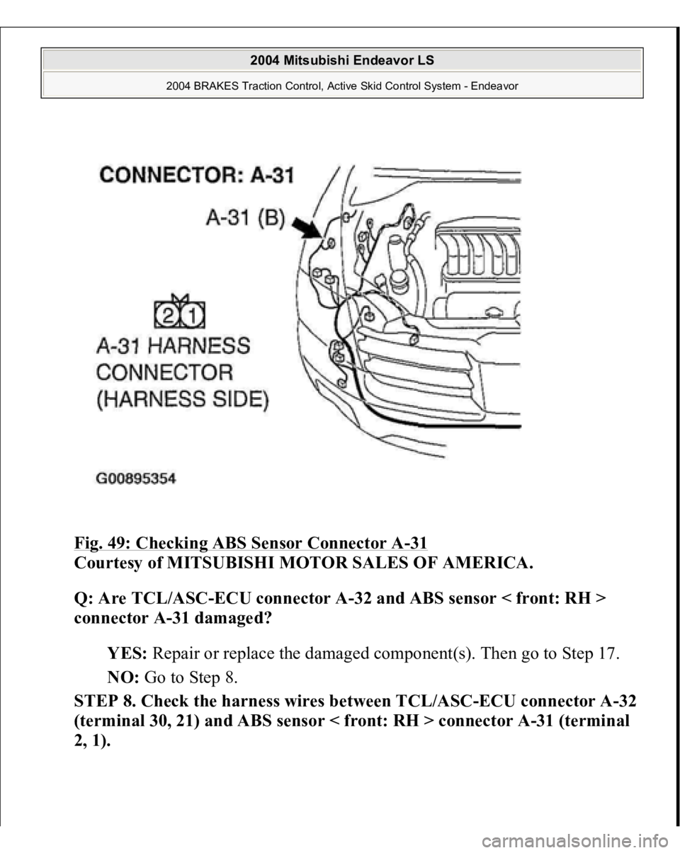
Fig. 49: Checking ABS Sensor Connector A
-31
Courtesy of MITSUBISHI MOTOR SALES OF AMERICA.
Q: Are TCL/ASC-ECU connector A-32 and ABS sensor < front: RH >
connector A-31 damaged?
YES: Repair or replace the damaged component(s). Then go to Step 17.
NO: Go to Step 8.
STEP 8. Check the harness wires between TCL/ASC-ECU connector A-32
(terminal 30, 21) and ABS sensor < front: RH > connector A-31 (terminal
2, 1).
2004 Mitsubishi Endeavor LS
2004 BRAKES Traction Control, Active Skid Control System - Endeavor
Page 3174 of 3870
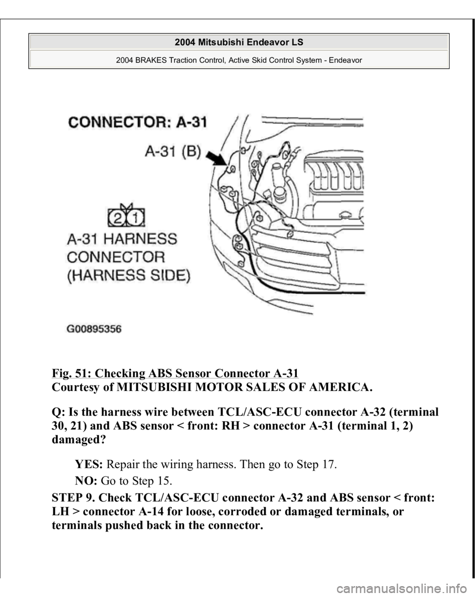
Fig. 51: Checking ABS Sensor Connector A
-31
Courtesy of MITSUBISHI MOTOR SALES OF AMERICA.
Q: Is the harness wire between TCL/ASC-ECU connector A-32 (terminal
30, 21) and ABS sensor < front: RH > connector A-31 (terminal 1, 2)
damaged?
YES: Repair the wiring harness. Then go to Step 17.
NO: Go to Step 15.
STEP 9. Check TCL/ASC-ECU connector A-32 and ABS sensor < front:
LH > connector A-14 for loose, corroded or damaged terminals, or
terminals pushed back in the connector.
2004 Mitsubishi Endeavor LS
2004 BRAKES Traction Control, Active Skid Control System - Endeavor