MITSUBISHI ENDEAVOR 2004 Service Repair Manual
ENDEAVOR 2004
MITSUBISHI
MITSUBISHI
https://www.carmanualsonline.info/img/19/57105/w960_57105-0.png
MITSUBISHI ENDEAVOR 2004 Service Repair Manual
Trending: air condition, purge valve, Lift point, cruise control, fuel pressure, steering wheel, parking brake
Page 2391 of 3870
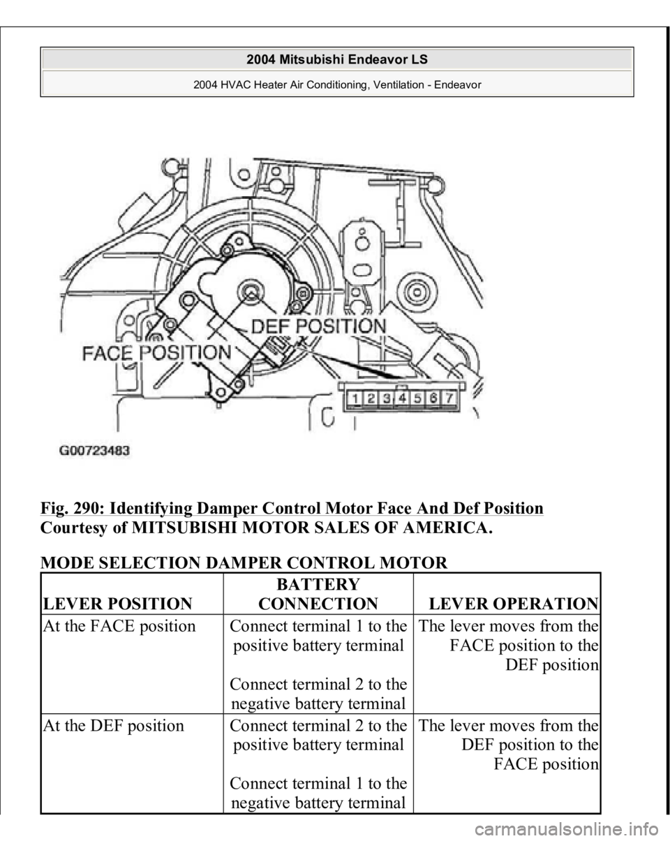
Fig. 290: Identifying Damper Control Motor Face And Def Position
Courtesy of MITSUBISHI MOTOR SALES OF AMERICA.
MODE SELECTION DAMPER CONTROL MOTOR
LEVER POSITION
BATTERY
CONNECTION
LEVER OPERATION
At the FACE position
Connect terminal 1 to the
positive battery terminal
Connect terminal 2 to the
negative battery terminal
The lever moves from the
FACE position to the
DEF position
At the DEF position
Connect terminal 2 to the
positive battery terminal
Connect terminal 1 to the
negative battery terminal
The lever moves from the
DEF position to the
FACE position
2004 Mitsubishi Endeavor LS
2004 HVAC Heater Air Conditioning, Ventilation - Endeavor
Page 2392 of 3870
POTENTIOMETER CHECK While checking the mode selection damper control motor, measure the resistances
between terminal numbers 3 and 5 and between terminal numbers 3 and 7. At this
time, the resistances should change gradually within the standard value. Standard value: 0.8 (DEF) - 4.8 (FACE) kohm
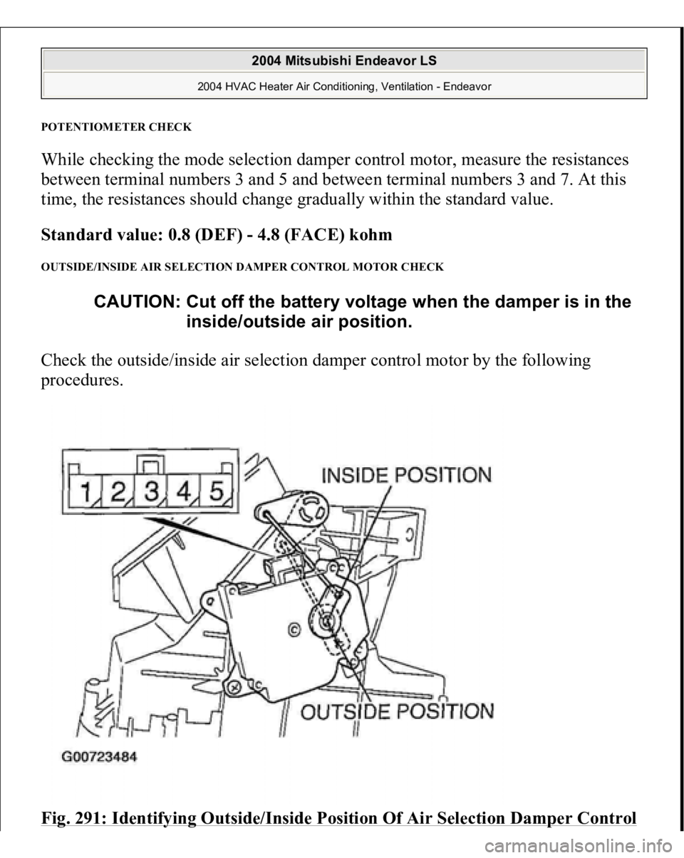
OUTSIDE/INSIDE AIR SELECTION DAMPER CONTROL MOTOR CHECK Check the outside/inside air selection damper control motor by the following
procedures. Fig. 291: Identifying Outside/Inside Position Of Air Selection Damper Control
CAUTION: Cut off the battery voltage when the damper is in the
inside/outside air position.
2004 Mitsubishi Endeavor LS
2004 HVAC Heater Air Conditioning, Ventilation - Endeavor
Page 2393 of 3870
Motor
Courtesy of MITSUBISHI MOTOR SALES OF AMERICA.
DAMPER CONTROL MOTOR OUTSIDE/INSIDE AIR SELECTION
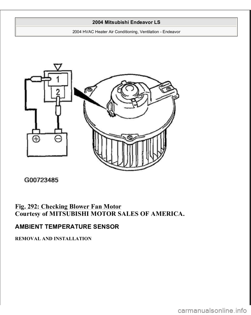
BLOWER FAN AND MOTOR CHECK When battery voltage is applied between the terminals, check that the motor
operates. Also, check that there is no abnormal noise. LEVER POSITION
BATTERY
CONNECTION
LEVER OPERATION
At the inside position
Connect terminal 1 to the
positive battery terminal
Connect terminal 5 to the
negative battery terminal
The lever moves from the
outside position to the
inside position
At the outside position
Connect terminal 1 to the
positive battery terminal
Connect terminal 4 to the
negative battery terminal
The lever moves from the
inside position to the
outside position
2004 Mitsubishi Endeavor LS
2004 HVAC Heater Air Conditioning, Ventilation - Endeavor
Page 2394 of 3870
Fig. 292: Checking Blower Fan Motor
Courtesy of MITSUBISHI MOTOR SALES OF AMERICA.
AMBIENT TEMPERATURE SENSOR REMOVAL AND INSTALLATION
2004 Mitsubishi Endeavor LS
2004 HVAC Heater Air Conditioning, Ventilation - Endeavor
Page 2395 of 3870
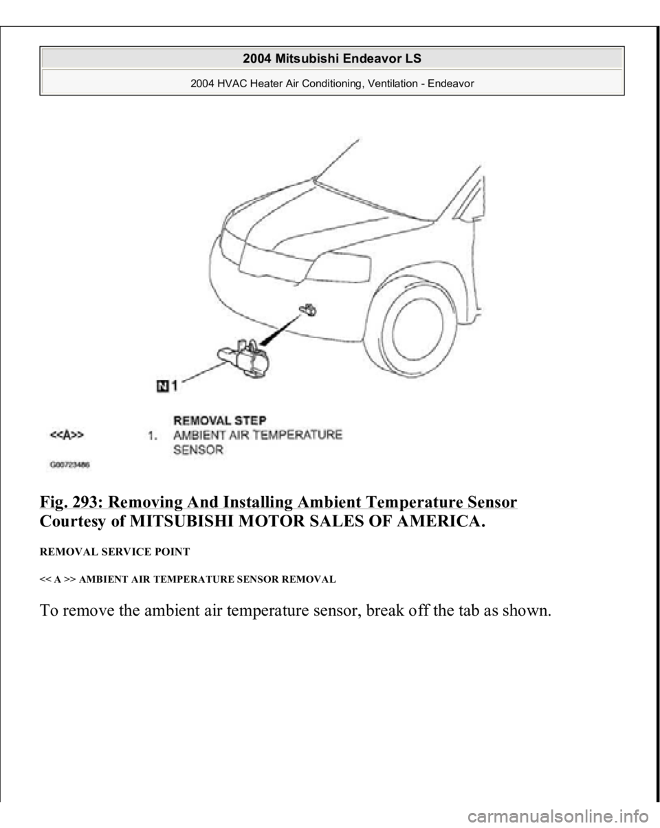
Fig. 293: Removing And Installing Ambient Temperature Sensor
Courtesy of MITSUBISHI MOTOR SALES OF AMERICA.
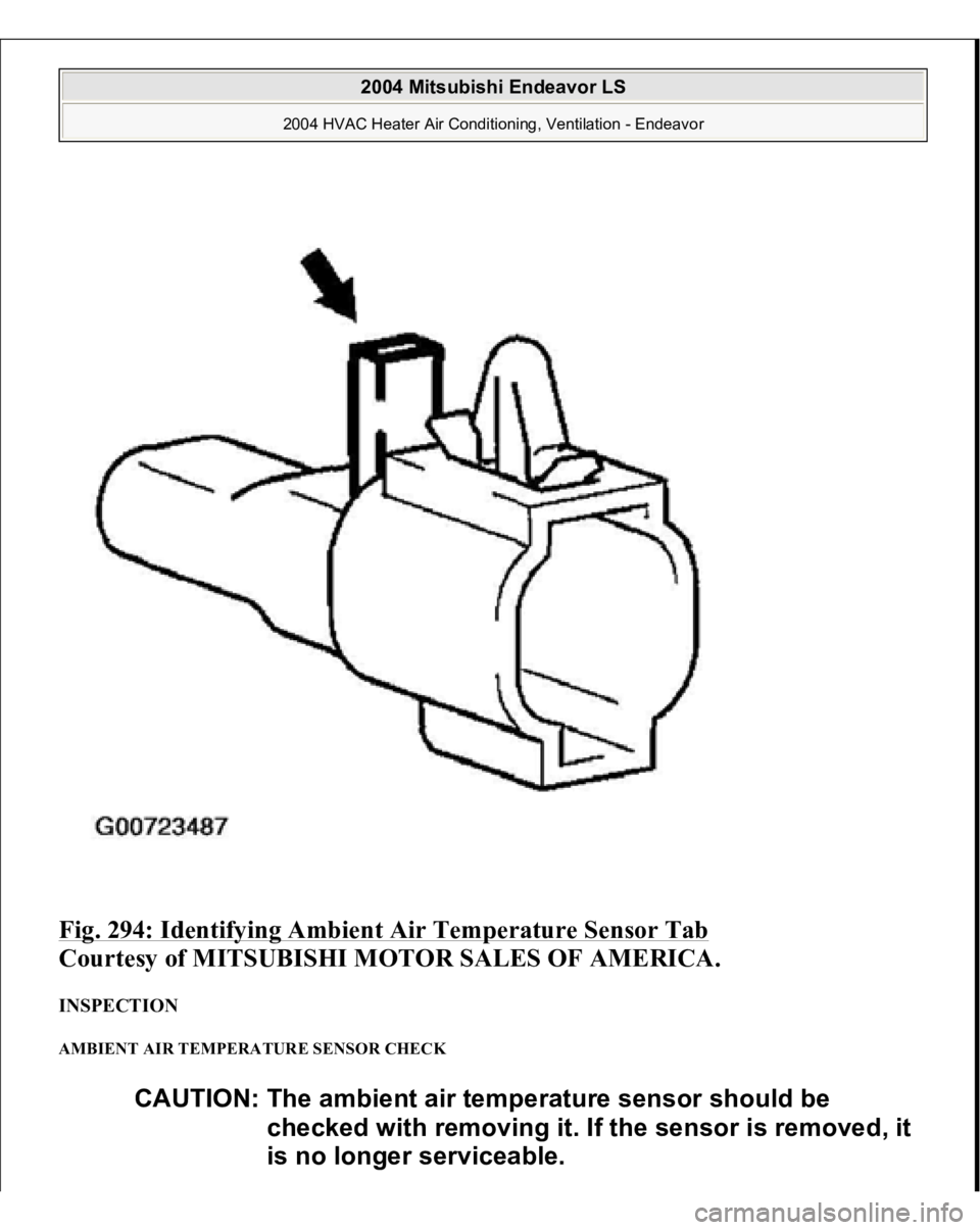
REMOVAL SERVICE POINT << A >> AMBIENT AIR TEMPERATURE SENSOR REMOVAL To remove the ambient air tem
perature sensor, brea
k off the tab as shown.
2004 Mitsubishi Endeavor LS
2004 HVAC Heater Air Conditioning, Ventilation - Endeavor
Page 2396 of 3870
Fig. 294: Identifying Ambient Air Temperature Sensor Tab
Courtesy of MITSUBISHI MOTOR SALES OF AMERICA.
INSPECTION AMBIENT AIR TEMPERATURE SENSOR CHECK
CAUTION: The ambient air temperature sensor should be
checked with removing it. If the sensor is removed, it
is no longer serviceable.
2004 Mitsubishi Endeavor LS
2004 HVAC Heater Air Conditioning, Ventilation - Endeavor
Page 2397 of 3870
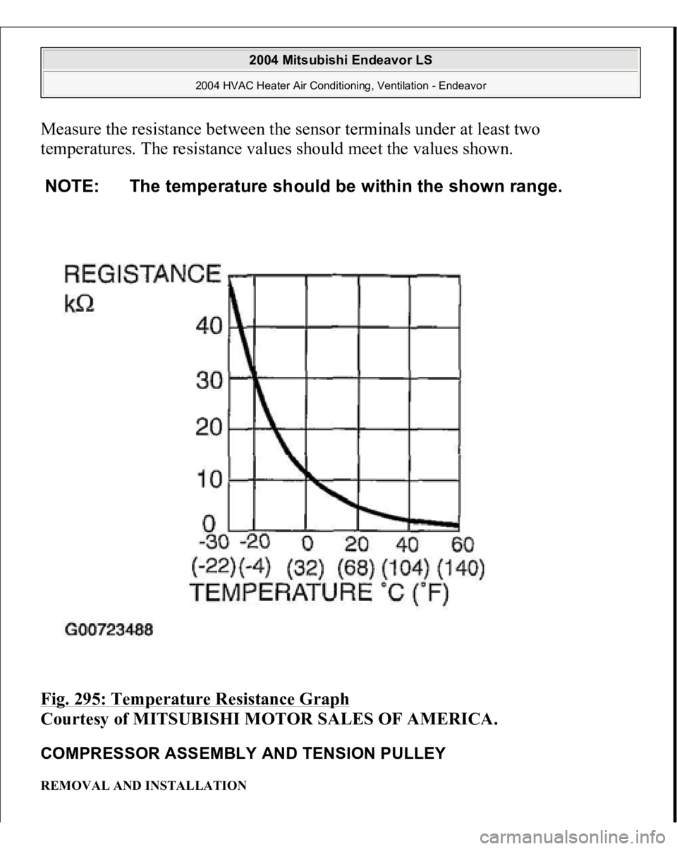
Measure the resistance between the sensor terminals under at least two
temperatures. The resistance values should meet the values shown. Fig. 295: Temperature Resistance Graph
Courtesy of MITSUBISHI MOTOR SALES OF AMERICA.
COMPRESSOR ASSEMBLY AND TENSION PULLEY REMOVAL AND INSTALLATION NOTE: The temperature should be within the shown range.
2004 Mitsubishi Endeavor LS
2004 HVAC Heater Air Conditioning, Ventilation - Endeavor
Page 2398 of 3870
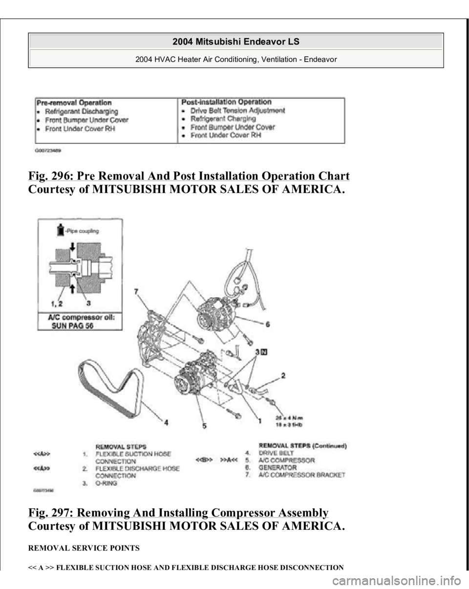
Fig. 296: Pre Removal And Post Installation Operation Chart
Courtesy of MITSUBISHI MOTOR SALES OF AMERICA.
Fig. 297: Removing And Installing Compressor Assembly
Courtesy of MITSUBISHI MOTOR SALES OF AMERICA.
REMOVAL SERVICE POINTS << A >> FLEXIBLE SUCTION HOSE AND FLEXIBLE DISCHARGE HOSE DISCONNECTION
2004 Mitsubishi Endeavor LS
2004 HVAC Heater Air Conditioning, Ventilation - Endeavor
Page 2399 of 3870
To prevent the entry of dust or other foreign bodies, plug the dismantled hoses and
compressor nipples. << B >> COMPRESSOR REMOVAL Take care not to spill any compressor oil when removing the compressor. INSTALLATION SERVICE POINT >> A << COMPRESSOR INSTALLATION If a new compressor is installed, first adjust the amount of oil according to the
procedures described below, and then install the compressor.
1. Measure the amount [X cm
3 (X fl.oz) of oil within the removed compressor.
2. Drain (from the new compressor) the amount of oil calculated according to the
following formula, and then install the new compressor.
New compressor oil amount = 140cm
2 (4.7 fl.oz)
140 cm
3 - X cm
3 = Y cm
3 (4.7 fl.oz. - X fl.oz. = Y fl.oz)
Quantity:
Eva
porator
: 60 c
m3 (2.0 fl.oz
)
CAUTION: As the compressor oil and receiver are highly
moisture absorbent, use a non-porous material to
plug the hose and nipples.
NOTE:
Y cm
3 (Y fl.oz) indicates the amount of oil in the refrigerant
line, the condenser, the evaporator, etc.
NOTE: When replacing the following parts at the same times as the
compressor, subtract the rated oil amount of each part from
Y cm3 (Y fl.oz) and discharge from the new compressor.
2004 Mitsubishi Endeavor LS
2004 HVAC Heater Air Conditioning, Ventilation - Endeavor
Page 2400 of 3870
Condenser:
15 cm
3 (0.5 fl.oz)
Suction hose:
10 cm
3 (0.3 fl.oz)
Receiver:
10 cm
3 (0.3 fl.oz)
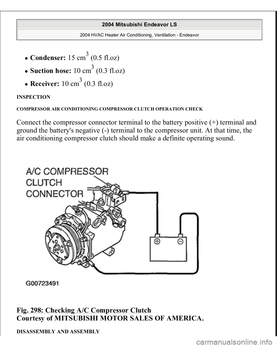
INSPECTION COMPRESSOR AIR CONDITIONING COMPRESSOR CLUTCH OPERATION CHECK Connect the compressor connector terminal to the battery positive (+) terminal and
ground the battery's negative (-) terminal to the compressor unit. At that time, the
air conditioning compressor clutch should make a definite operating sound. Fig. 298: Checking A/C Compressor Clutch
Courtesy of MITSUBISHI MOTOR SALES OF AMERICA.
DISASSEMBLY AND ASSEMBLY
2004 Mitsubishi Endeavor LS
2004 HVAC Heater Air Conditioning, Ventilation - Endeavor
Trending: diagram, crankshaft position sensor, clock light, airbag, seats, lock, roof
