MITSUBISHI ENDEAVOR 2004 Service Repair Manual
ENDEAVOR 2004
MITSUBISHI
MITSUBISHI
https://www.carmanualsonline.info/img/19/57105/w960_57105-0.png
MITSUBISHI ENDEAVOR 2004 Service Repair Manual
Trending: body, Ball joint nut, windshield wipers, Oxygen O2 sensor, remote start, instrument panel, Ac compressor
Page 2401 of 3870
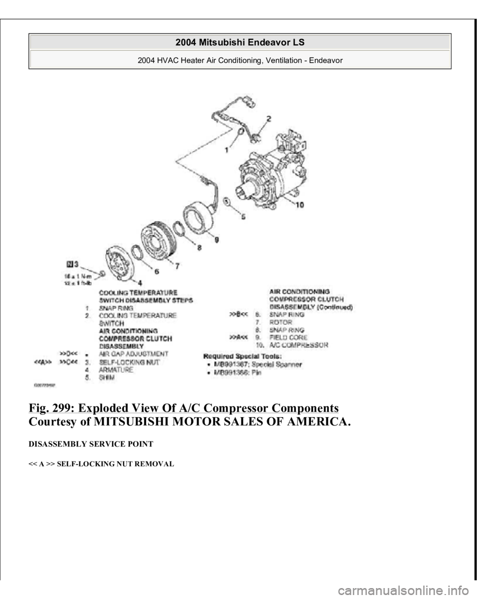
Fig. 299: Exploded View Of A/C Compressor Components
Courtesy of MITSUBISHI MOTOR SALES OF AMERICA.
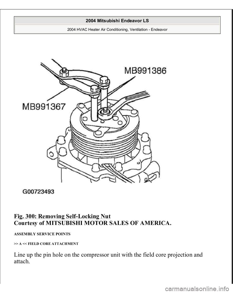
DISASSEMBLY SERVICE POINT << A >> SELF-LOCKING NUT REMOVAL
2004 Mitsubishi Endeavor LS
2004 HVAC Heater Air Conditioning, Ventilation - Endeavor
Page 2402 of 3870
Fig. 300: Removing Self
-Locking Nut
Courtesy of MITSUBISHI MOTOR SALES OF AMERICA.
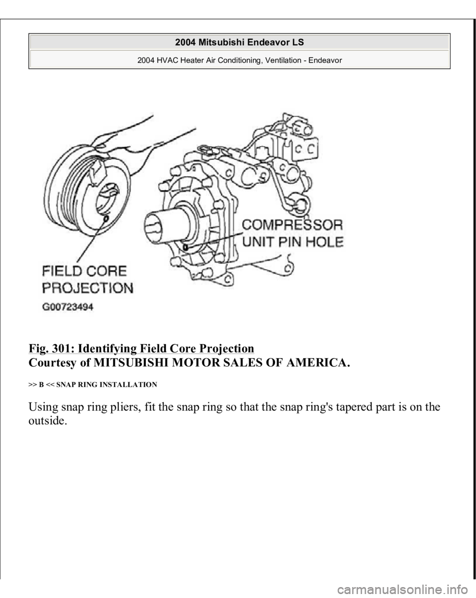
ASSEMBLY SERVICE POINTS >> A << FIELD CORE ATTACHMENT Line up the pin hole on the compressor unit with the field core projection and
attach.
2004 Mitsubishi Endeavor LS
2004 HVAC Heater Air Conditioning, Ventilation - Endeavor
Page 2403 of 3870
Fig. 301: Identifying Field Core Projection
Courtesy of MITSUBISHI MOTOR SALES OF AMERICA.
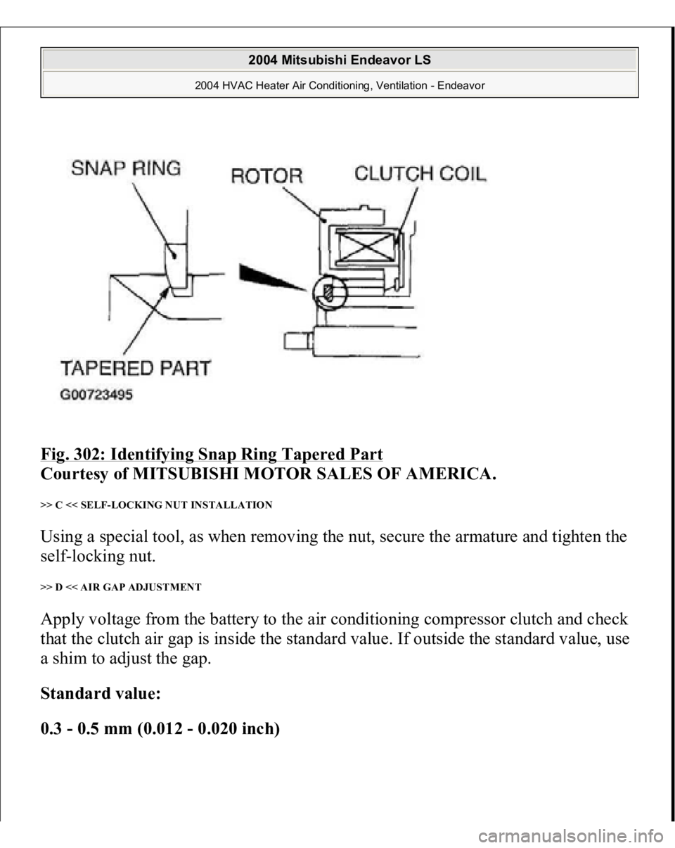
>> B << SNAP RING INSTALLATION Using snap ring pliers, fit the snap ring so that the snap ring's tapered part is on the
outside.
2004 Mitsubishi Endeavor LS
2004 HVAC Heater Air Conditioning, Ventilation - Endeavor
Page 2404 of 3870
Fig. 302: Identifying Snap Ring Tapered Part
Courtesy of MITSUBISHI MOTOR SALES OF AMERICA.
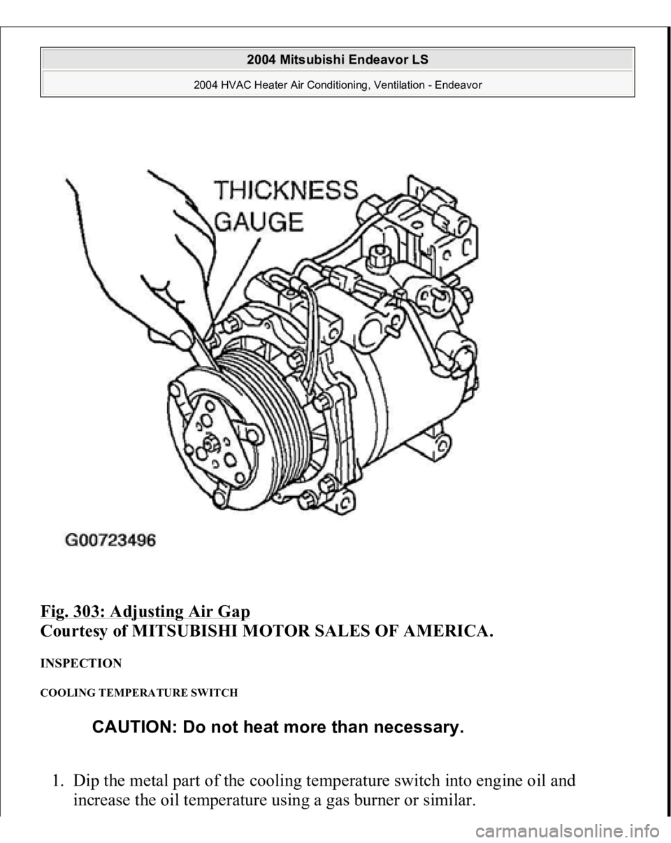
>> C << SELF-LOCKING NUT INSTALLATION Using a special tool, as when removing the nut, secure the armature and tighten the
self-locking nut. >> D << AIR GAP ADJUSTMENT Apply voltage from the battery to the air conditioning compressor clutch and check
that the clutch air gap is inside the standard value. If outside the standard value, use
a shim to adjust the gap. Standard value:
0.3 - 0.5 mm (0.012 - 0.020 inch)
2004 Mitsubishi Endeavor LS
2004 HVAC Heater Air Conditioning, Ventilation - Endeavor
Page 2405 of 3870
Fig. 303: Adjusting Air Gap
Courtesy of MITSUBISHI MOTOR SALES OF AMERICA.
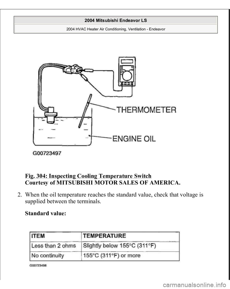
INSPECTION COOLING TEMPERATURE SWITCH 1. Dip the metal part of the cooling temperature switch into engine oil and
increase the oil temperature using a gas burner or similar.
CAUTION: Do not heat more than necessary.
2004 Mitsubishi Endeavor LS
2004 HVAC Heater Air Conditioning, Ventilation - Endeavor
Page 2406 of 3870
Fig. 304: Inspecting Cooling Temperature Switch
Courtesy of MITSUBISHI MOTOR SALES OF AMERICA.
2. When the oil temperature reaches the standard value, check that voltage is
supplied between the terminals.
Standard value:
2004 Mitsubishi Endeavor LS
2004 HVAC Heater Air Conditioning, Ventilation - Endeavor
Page 2407 of 3870
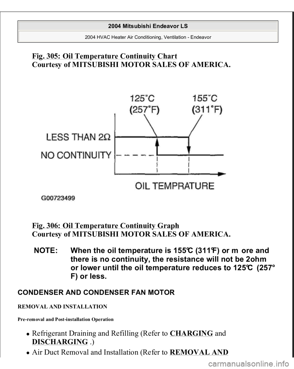
Fig. 305: Oil Temperature Continuity Char
t
Courtesy of MITSUBISHI MOTOR SALES OF AMERICA.
Fig. 306: Oil Temperature Continuity Graph
Courtesy of MITSUBISHI MOTOR SALES OF AMERICA.
CONDENSER AND CONDENSER FAN MOTOR REMOVAL AND INSTALLATION Pre-removal and Post-installation Operation
Refrigerant Draining and Refilling (Refer to
CHARGING
and
DISCHARGING
.)
Air Duct Removal and Installation
(Refer to
REMOVAL AND
NOTE: When the oil temperature is 155°C (311°F) or m ore and
there is no continuity, the resistance will not be 2ohm
or lower until the oil temperature reduces to 125°C (257°
F) or less.
2004 Mitsubishi Endeavor LS
2004 HVAC Heater Air Conditioning, Ventilation - Endeavor
Page 2408 of 3870
INSTALLATION
.)
Radiator Grilles Removal and Installation (Refer to
RADIATOR
.)
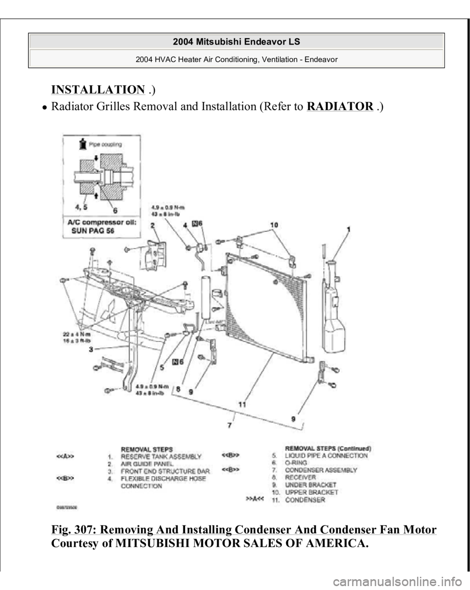
Fig. 307: Removing And Installing Condenser And Condenser Fan Motor
Courtesy of MITSUBISHI MOTOR SALES OF AMERICA.
2004 Mitsubishi Endeavor LS
2004 HVAC Heater Air Conditioning, Ventilation - Endeavor
Page 2409 of 3870
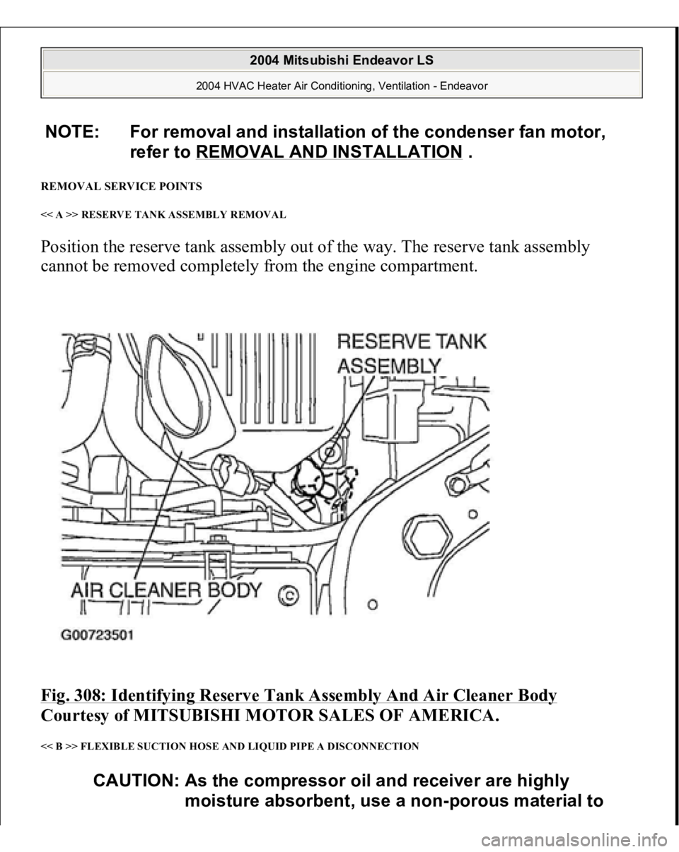
REMOVAL SERVICE POINTS << A >> RESERVE TANK ASSEMBLY REMOVAL Position the reserve tank assembly out of the way. The reserve tank assembly
cannot be removed completely from the engine compartment. Fig. 308: Identifying Reserve Tank Assembly And Air Cleaner Body
Courtesy of MITSUBISHI MOTOR SALES OF AMERICA.
<< B >> FLEXIBLE SUCTION HOSE AND LIQUID PIPE A DISCONNECTION NOTE: For removal and installation of the condenser fan motor,
refer to REMOVAL AND INSTALLATION
.
CAUTION: As the compressor oil and receiver are highly
moisture absorbent, use a non-porous material to
2004 Mitsubishi Endeavor LS
2004 HVAC Heater Air Conditioning, Ventilation - Endeavor
Page 2410 of 3870
To prevent the entry of dust or other foreign bodies, plug the dismantled hose and
condenser assembly nipples. INSTALLATION SERVICE POINT >> A << CONDENSER INSTALLATION When replacing the condenser, refill it with a specified amount of compressor oil
and install it to the vehicle.
Compressor oil: SUN PAG 56
Quantity:
15 cm
3 (0.5 fl.oz)
INSPECTION CONDENSER FAN MOTOR CHECK Check to be sure that the condenser fan motor operates when battery voltage is
applied to terminal 2 and terminal 1
grounded.
plug the hose and nipples.
2004 Mitsubishi Endeavor LS
2004 HVAC Heater Air Conditioning, Ventilation - Endeavor
Trending: door alarm, power steering, jack, fuse diagram, fuel pump, jump cable, oil change
