MITSUBISHI ENDEAVOR 2004 Service Repair Manual
ENDEAVOR 2004
MITSUBISHI
MITSUBISHI
https://www.carmanualsonline.info/img/19/57105/w960_57105-0.png
MITSUBISHI ENDEAVOR 2004 Service Repair Manual
Trending: oxygen, transmission oil, heating, center console, Batter, accessory belt, display
Page 2961 of 3870
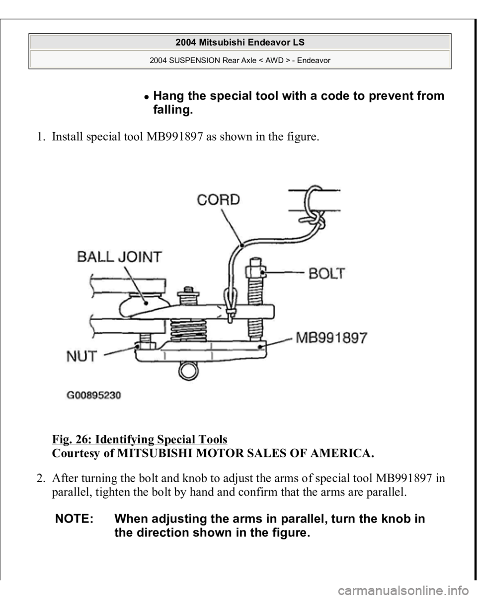
1. Install special tool MB991897 as shown in the figure.
Fig. 26: Identifying Special Tools
Courtesy of MITSUBISHI MOTOR SALES OF AMERICA.
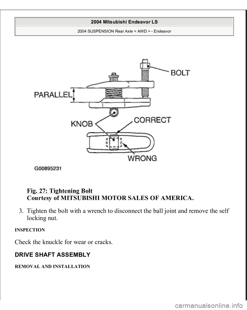
2. After turning the bolt and knob to adjust the arms of special tool MB991897 in
parallel, tighten the bolt by hand and confirm that the arms are parallel.
Hang the special tool with a code to prevent from
falling.
NOTE: When adjusting the arms in parallel, turn the knob in
the direction shown in the figure.
2004 Mitsubishi Endeavor LS
2004 SUSPENSION Rear Axle < AWD > - Endeavor
Page 2962 of 3870
Fig. 27: Tightening Bolt
Courtesy of MITSUBISHI MOTOR SALES OF AMERICA.
3. Tighten the bolt with a wrench to disconnect the ball joint and remove the self
locking nut.
INSPECTION Check the knuckle for wear or cracks. DRIVE SHAFT ASSEMBLY REMOVAL AND INSTALLATION
2004 Mitsubishi Endeavor LS
2004 SUSPENSION Rear Axle < AWD > - Endeavor
Page 2963 of 3870
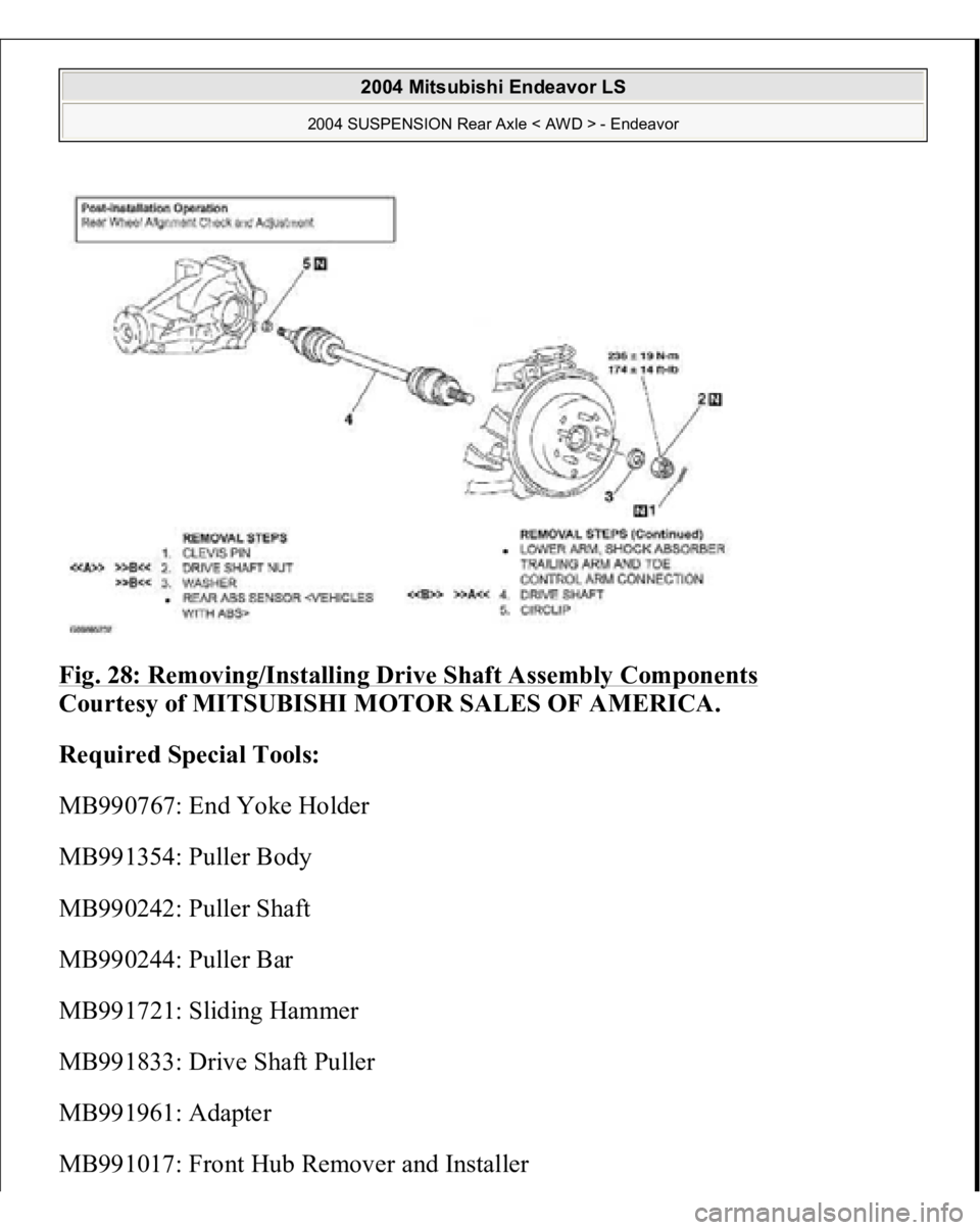
Fig. 28: Removing/Installing Drive Shaft Assembly Components
Courtesy of MITSUBISHI MOTOR SALES OF AMERICA.
Required Special Tools:
MB990767: End Yoke Holder
MB991354: Puller Body
MB990242: Puller Shaft
MB990244: Puller Bar
MB991721: Sliding Hammer
MB991833: Drive Shaft Puller
MB991961: Adapter
MB991017: Front Hub Remover and Installe
r
2004 Mitsubishi Endeavor LS
2004 SUSPENSION Rear Axle < AWD > - Endeavor
Page 2964 of 3870
Page 2965 of 3870
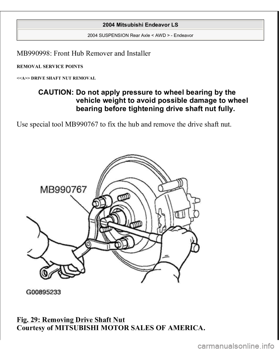
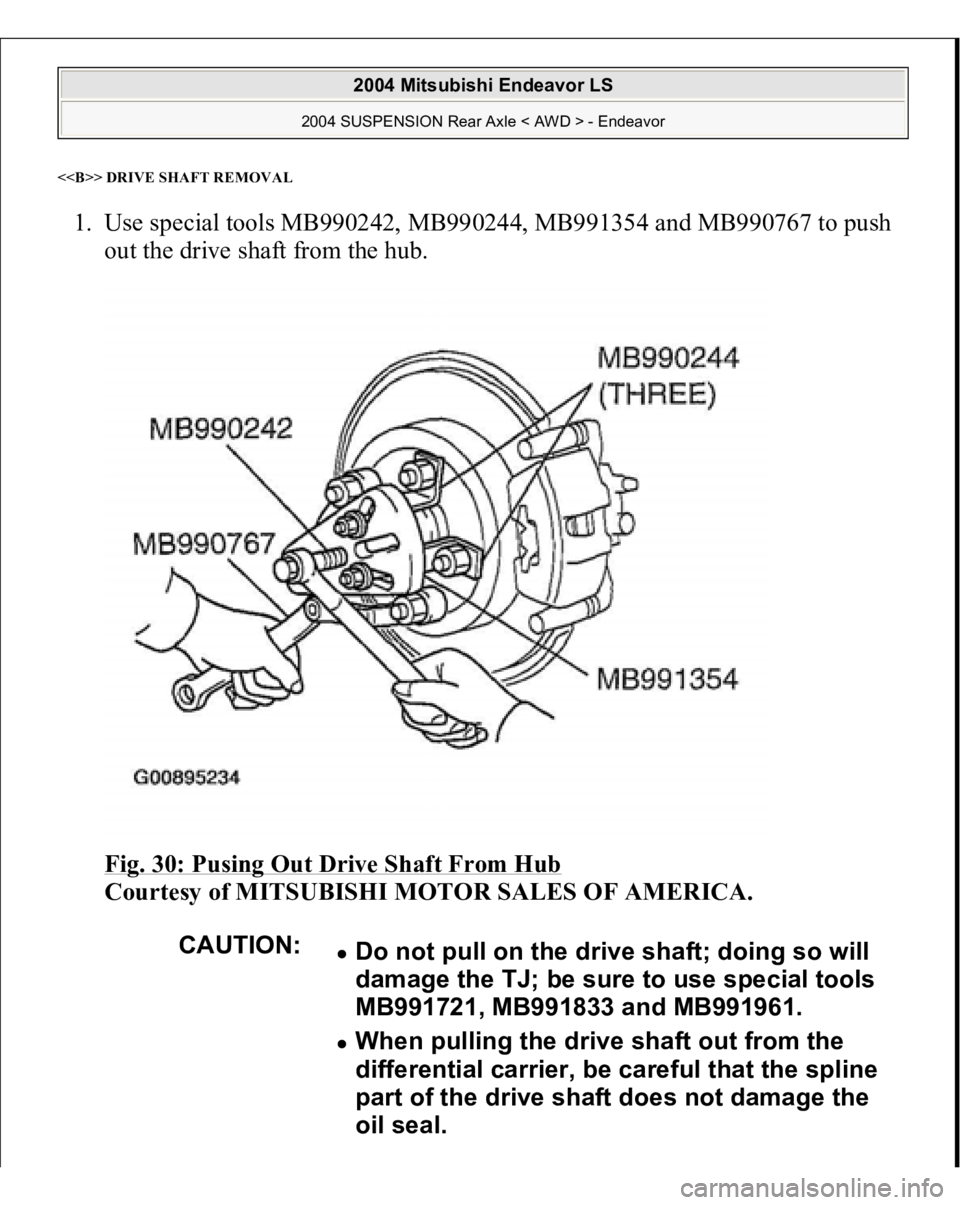
<> DRIVE SHAFT REMOVA
L
1. Use special tools MB990242, MB990244, MB991354 and MB990767 to push
out the drive shaft from the hub.
Fig. 30: Pusing Out Drive Shaft From Hub
Courtesy of MITSUBISHI MOTOR SALES OF AMERICA.
CAUTION:
Do not pull on the drive shaft; doing so will
damage the TJ; be sure to use special tools
MB991721, MB991833 and MB991961. When pulling the drive shaft out from the
differential carrier, be careful that the spline
part of the drive shaft does not damage the
oil seal.
2004 Mitsubishi Endeavor LS
2004 SUSPENSION Rear Axle < AWD > - Endeavor
Page 2966 of 3870
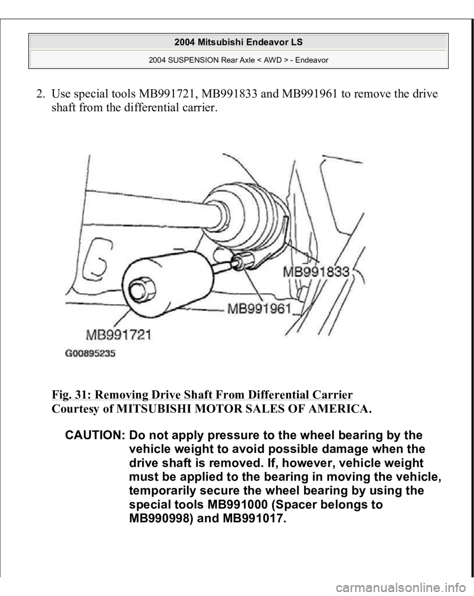
2. Use special tools MB991721, MB991833 and MB991961 to remove the drive
shaft from the differential carrier.
Fig. 31: Removing Drive Shaft From Differential Carrier
Courtesy of MITSUBISHI MOTOR SALES OF AMERICA.
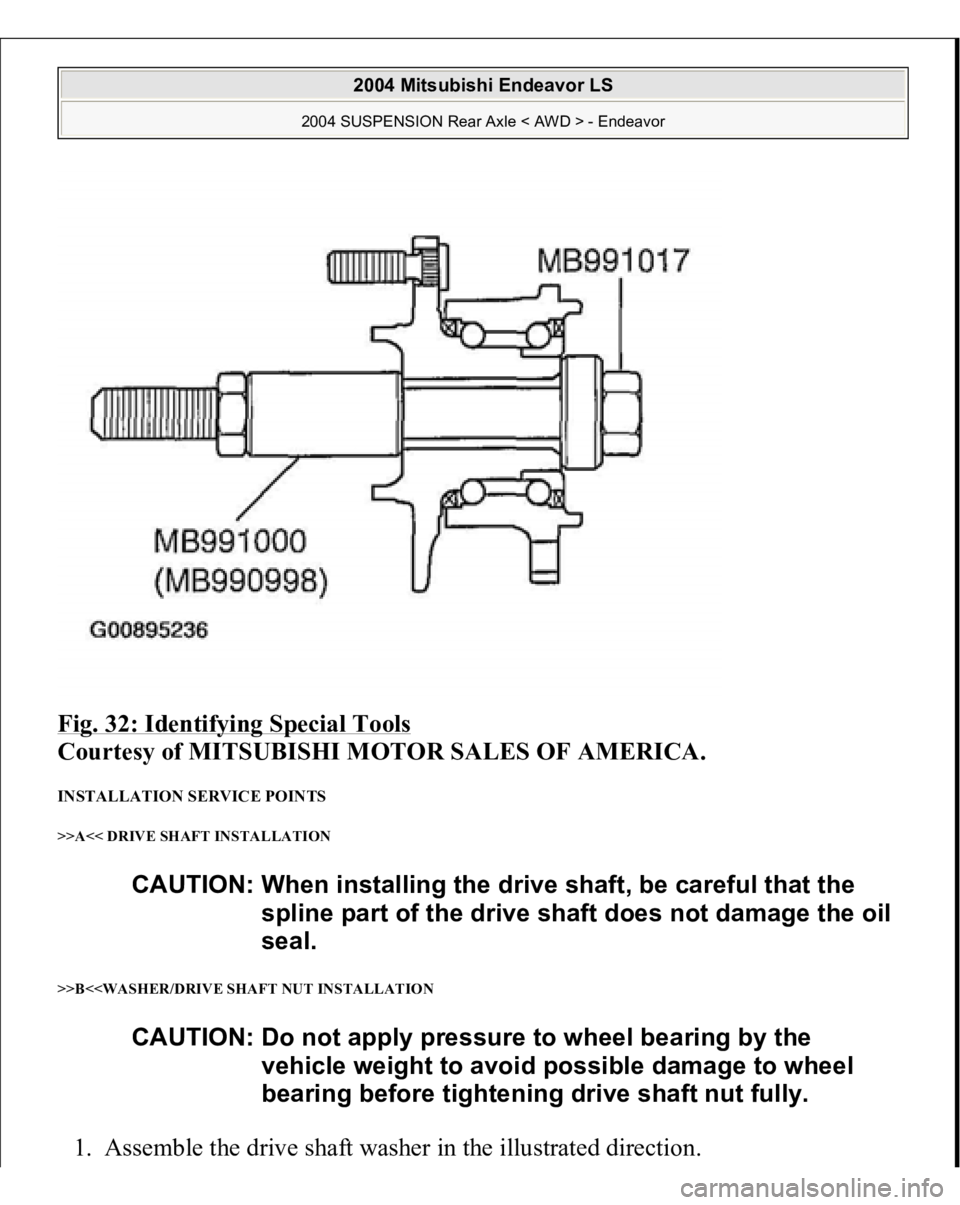
CAUTION: Do not apply pressure to the wheel bearing by the
vehicle weight to avoid possible damage when the
drive shaft is removed. If, however, vehicle weight
must be applied to the bearing in moving the vehicle,
temporarily secure the wheel bearing by using the
special tools MB991000 (Spacer belongs to
MB990998) and MB991017.
2004 Mitsubishi Endeavor LS
2004 SUSPENSION Rear Axle < AWD > - Endeavor
Page 2967 of 3870
Fig. 32: Identifying Special Tools
Courtesy of MITSUBISHI MOTOR SALES OF AMERICA.
INSTALLATION SERVICE POINTS >>A<< DRIVE SHAFT INSTALLATION
>>B<
CAUTION: When installing the drive shaft, be careful that the
spline part of the drive shaft does not damage the oil
seal.
CAUTION: Do not apply pressure to wheel bearing by the
vehicle weight to avoid possible damage to wheel
bearing before tightening drive shaft nut fully.
2004 Mitsubishi Endeavor LS
2004 SUSPENSION Rear Axle < AWD > - Endeavor
Page 2968 of 3870
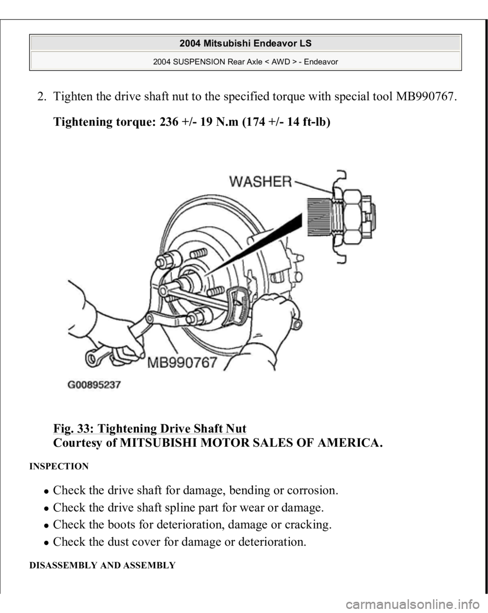
2. Tighten the drive shaft nut to the specified torque with special tool MB990767.
Tightening torque: 236 +/- 19 N.m (174 +/- 14 ft-lb)
Fig. 33: Tightening Drive Shaft Nut
Courtesy of MITSUBISHI MOTOR SALES OF AMERICA.
INSPECTION
Check the drive shaft for damage, bending or corrosion. Check the drive shaft spline part for wear or damage. Check the boots for deterioration, damage or cracking. Check the dust cover for damage or deterioration.
DISASSEMBLY AND ASSEMBLY
2004 Mitsubishi Endeavor LS
2004 SUSPENSION Rear Axle < AWD > - Endeavor
Page 2969 of 3870
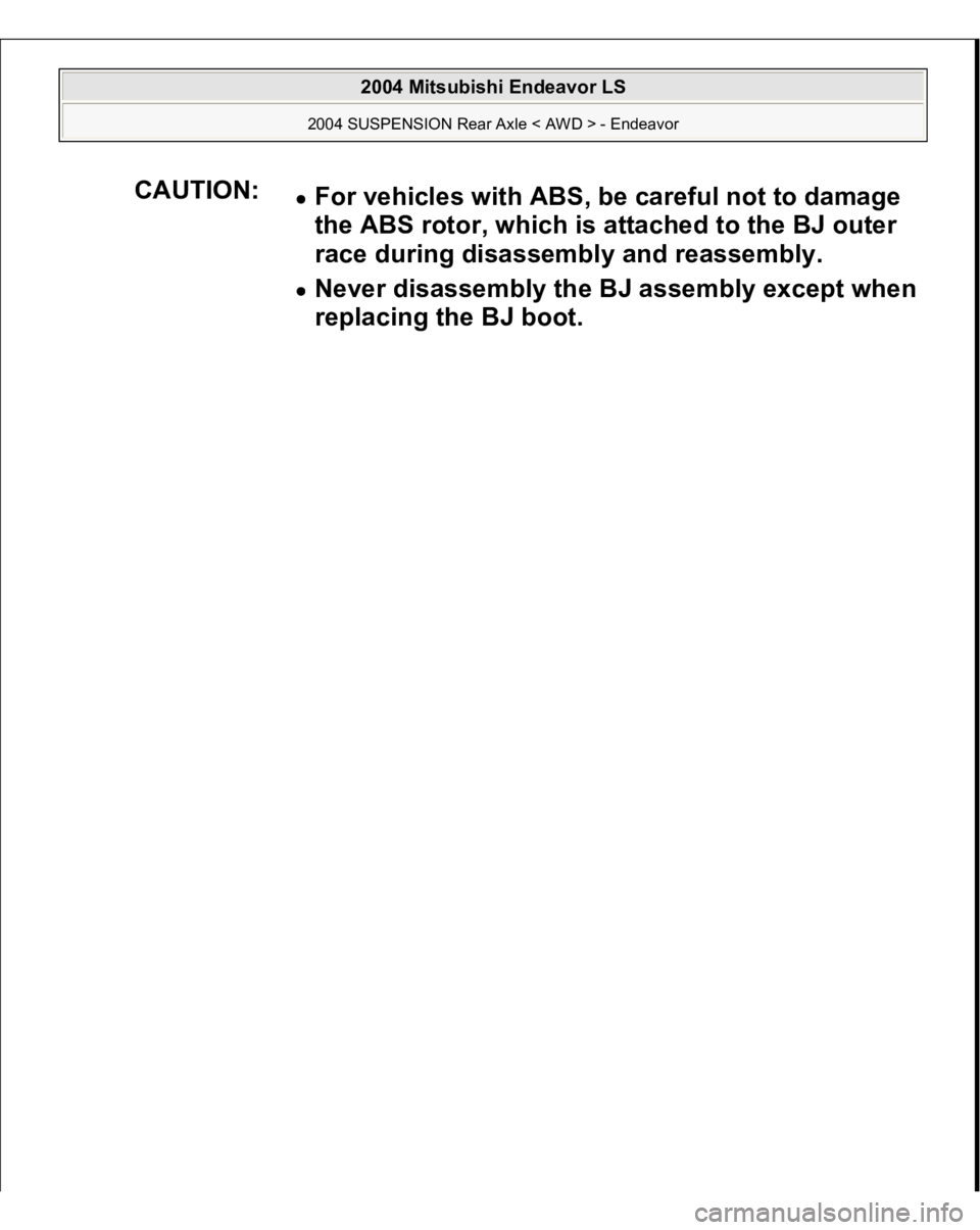
CAUTION:
For vehicles with ABS, be careful not to damage
the ABS rotor, which is attached to the BJ outer
race during disassembly and reassembly. Never disassembly the BJ assembly except when
replacing the BJ boot.
2004 Mitsubishi Endeavor LS
2004 SUSPENSION Rear Axle < AWD > - Endeavor
Page 2970 of 3870
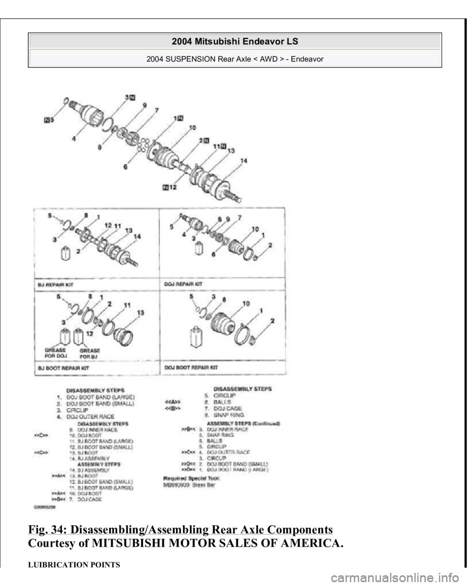
Fig. 34: Disassembling/Assembling Rear Axle Components
Courtesy of MITSUBISHI MOTOR SALES OF AMERICA.
LUIBRICATION POINTS
2004 Mitsubishi Endeavor LS
2004 SUSPENSION Rear Axle < AWD > - Endeavor
Trending: instrument panel, ESP, control module, Ac pressure switch, Battery terminals, bulb, O2 sensors
