MITSUBISHI ENDEAVOR 2004 Service Repair Manual
ENDEAVOR 2004
MITSUBISHI
MITSUBISHI
https://www.carmanualsonline.info/img/19/57105/w960_57105-0.png
MITSUBISHI ENDEAVOR 2004 Service Repair Manual
Trending: hood open, instrument cluster, sunroof, Immobilizer and or key ring antenna, test oxygen, Spark plugs, ad blue
Page 641 of 3870
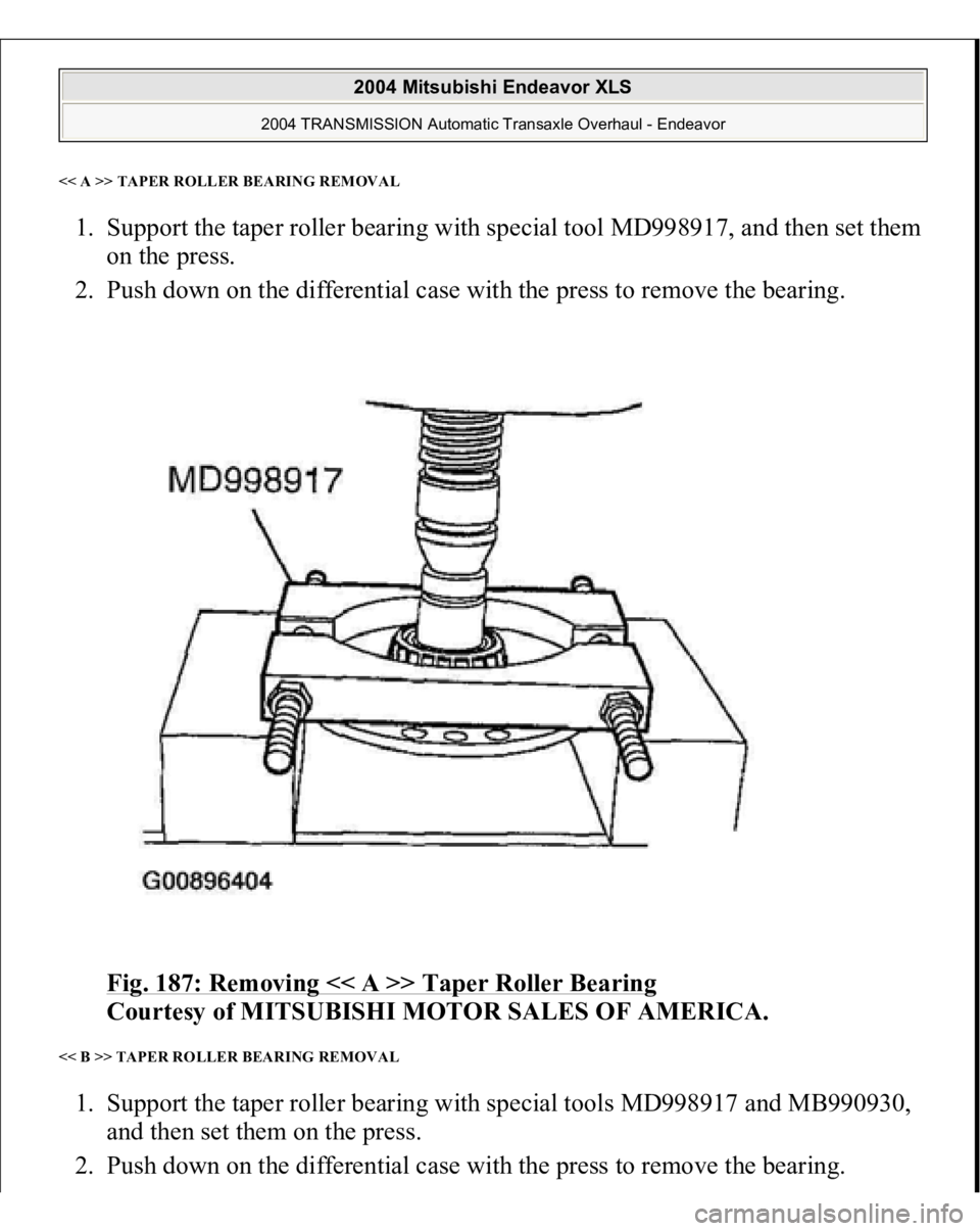
<< A >> TAPER ROLLER BEARING REMOVAL1. Support the taper roller bearing with special tool MD998917, and then set them
on the press.
2. Push down on the differential case with the press to remove the bearing.
Fig. 187: Removing << A >> Taper Roller Bearing
Courtesy of MITSUBISHI MOTOR SALES OF AMERICA.
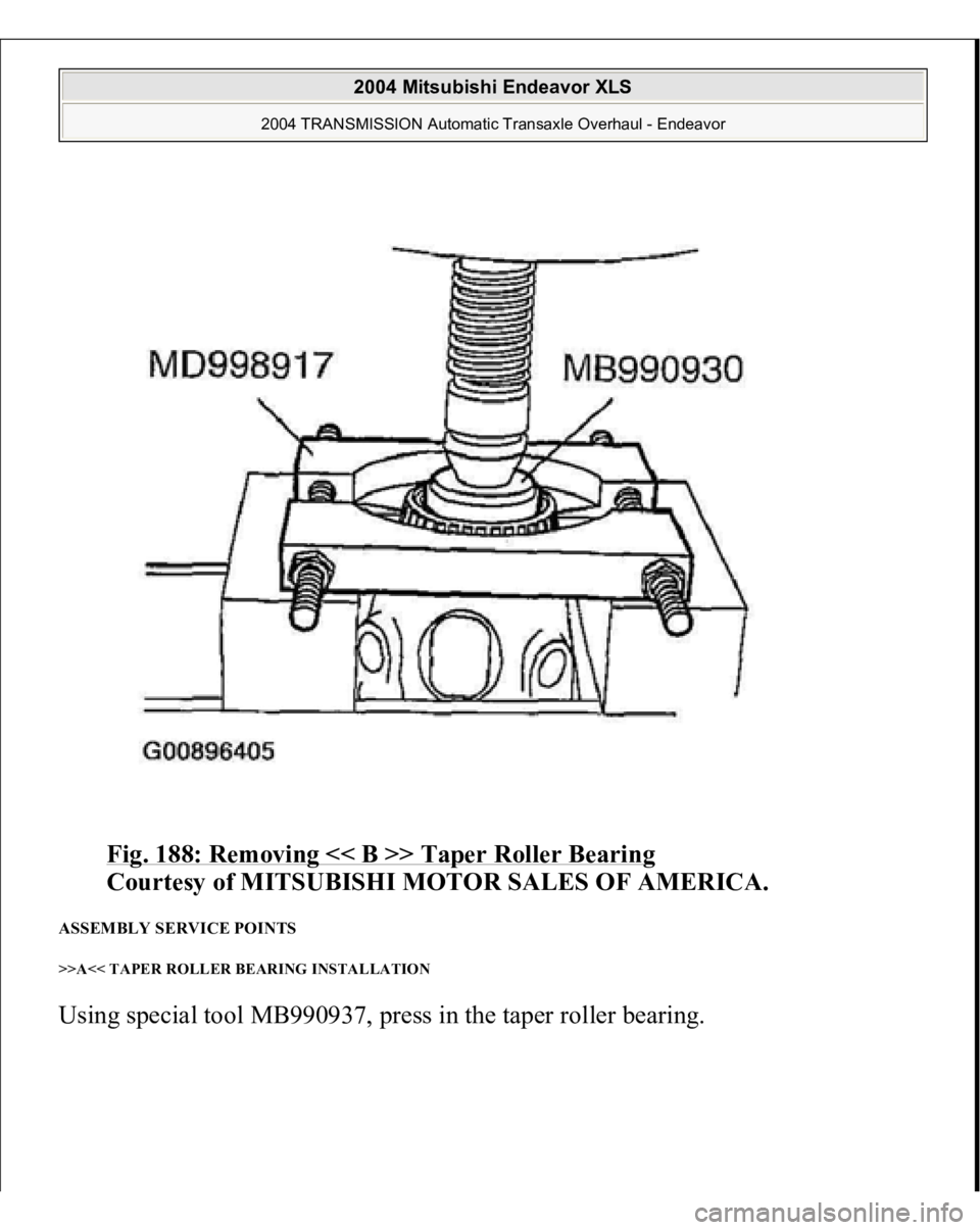
<< B >> TAPER ROLLER BEARING REMOVAL 1. Support the taper roller bearing with special tools MD998917 and MB990930,
and then set them on the press.
2. Push down on the differential case with the
press
to remove the bearin
g.
2004 Mitsubishi Endeavor XLS
2004 TRANSMISSION Automatic Transaxle Overhaul - Endeavor
Page 642 of 3870
Fig. 188: Removing << B >> Taper Roller Bearing
Courtesy of MITSUBISHI MOTOR SALES OF AMERICA.
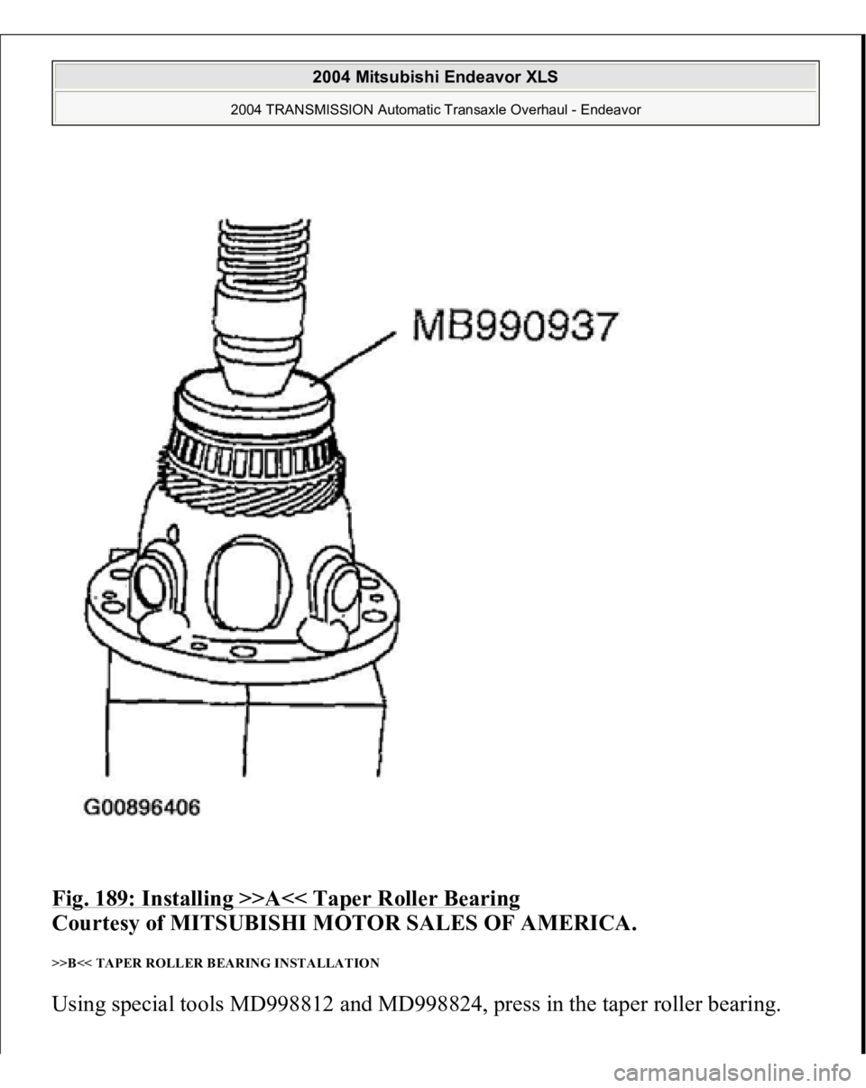
ASSEMBLY SERVICE POINTS >>A<< TAPER ROLLER BEARING INSTALLATION Usin
g special tool MB990937,
press in the ta
per roller bearin
g.
2004 Mitsubishi Endeavor XLS
2004 TRANSMISSION Automatic Transaxle Overhaul - Endeavor
Page 643 of 3870
Fig. 189: Installing >>A<< Taper Roller Bearing
Courtesy of MITSUBISHI MOTOR SALES OF AMERICA.
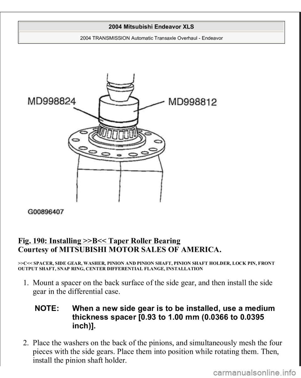
>>B<< TAPER ROLLER BEARING INSTALLATION Usin
g special tools MD998812 and MD998824,
press in the ta
per roller bearin
g.
2004 Mitsubishi Endeavor XLS
2004 TRANSMISSION Automatic Transaxle Overhaul - Endeavor
Page 644 of 3870
Fig. 190: Installing >>B<< Taper Roller Bearing
Courtesy of MITSUBISHI MOTOR SALES OF AMERICA.
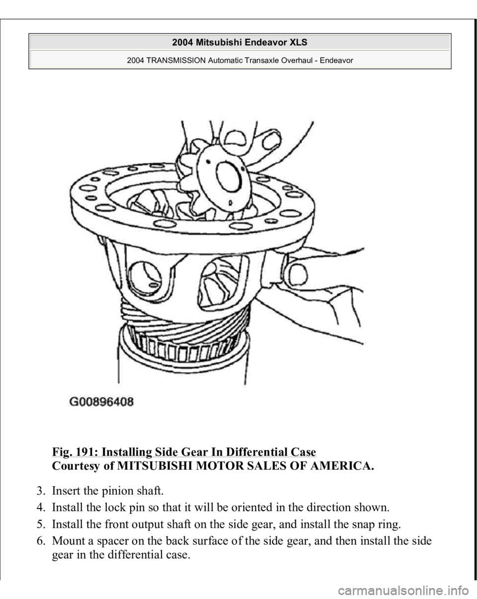
>>C<< SPACER, SIDE GEAR, WASHER, PINION AND PINION SHAFT, PINION SHAFT HOLDER, LOCK PIN, FRONT
OUTPUT SHAFT, SNAP RING, CENTER DIFFERENTIAL FLANGE, INSTALLATION 1. Mount a spacer on the back surface of the side gear, and then install the side
gear in the differential case.
2. Place the washers on the back of the pinions, and simultaneously mesh the four
pieces with the side gears. Place them into position while rotating them. Then,
install the
pinion shaft holder.
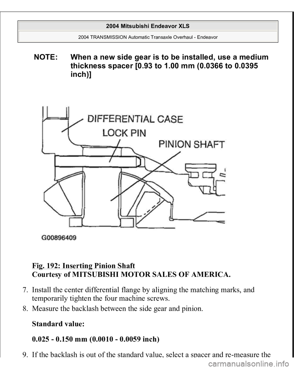
NOTE: When a new side gear is to be installed, use a medium
thickness spacer [0.93 to 1.00 mm (0.0366 to 0.0395
inch)].
2004 Mitsubishi Endeavor XLS
2004 TRANSMISSION Automatic Transaxle Overhaul - Endeavor
Page 645 of 3870
Fig. 191: Installing Side Gear In Differential Case
Courtesy of MITSUBISHI MOTOR SALES OF AMERICA.
3. Insert the pinion shaft.
4. Install the lock pin so that it will be oriented in the direction shown.
5. Install the front output shaft on the side gear, and install the snap ring.
6. Mount a spacer on the back surface of the side gear, and then install the side
gear in the differential case.
2004 Mitsubishi Endeavor XLS
2004 TRANSMISSION Automatic Transaxle Overhaul - Endeavor
Page 646 of 3870
Fig. 192: Inserting Pinion Shaft
Courtesy of MITSUBISHI MOTOR SALES OF AMERICA.
7. Install the center differential flange by aligning the matching marks, and
temporarily tighten the four machine screws.
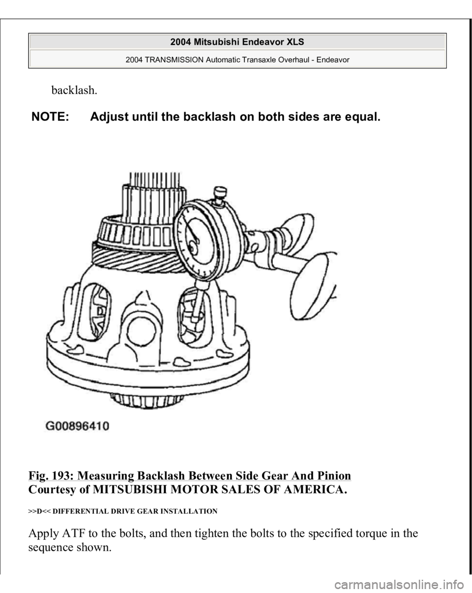
8. Measure the backlash between the side gear and pinion.
Standard value:
0.025 - 0.150 mm (0.0010 - 0.0059 inch)
9. If the backlash is out of the standard value
, select a s
pacer and r
e-measure the
NOTE: When a new side gear is to be installed, use a medium
thickness spacer [0.93 to 1.00 mm (0.0366 to 0.0395
inch)]
2004 Mitsubishi Endeavor XLS
2004 TRANSMISSION Automatic Transaxle Overhaul - Endeavor
Page 647 of 3870
backlash.
Fig. 193: Measuring Backlash Between Side Gear And Pinion
Courtesy of MITSUBISHI MOTOR SALES OF AMERICA.
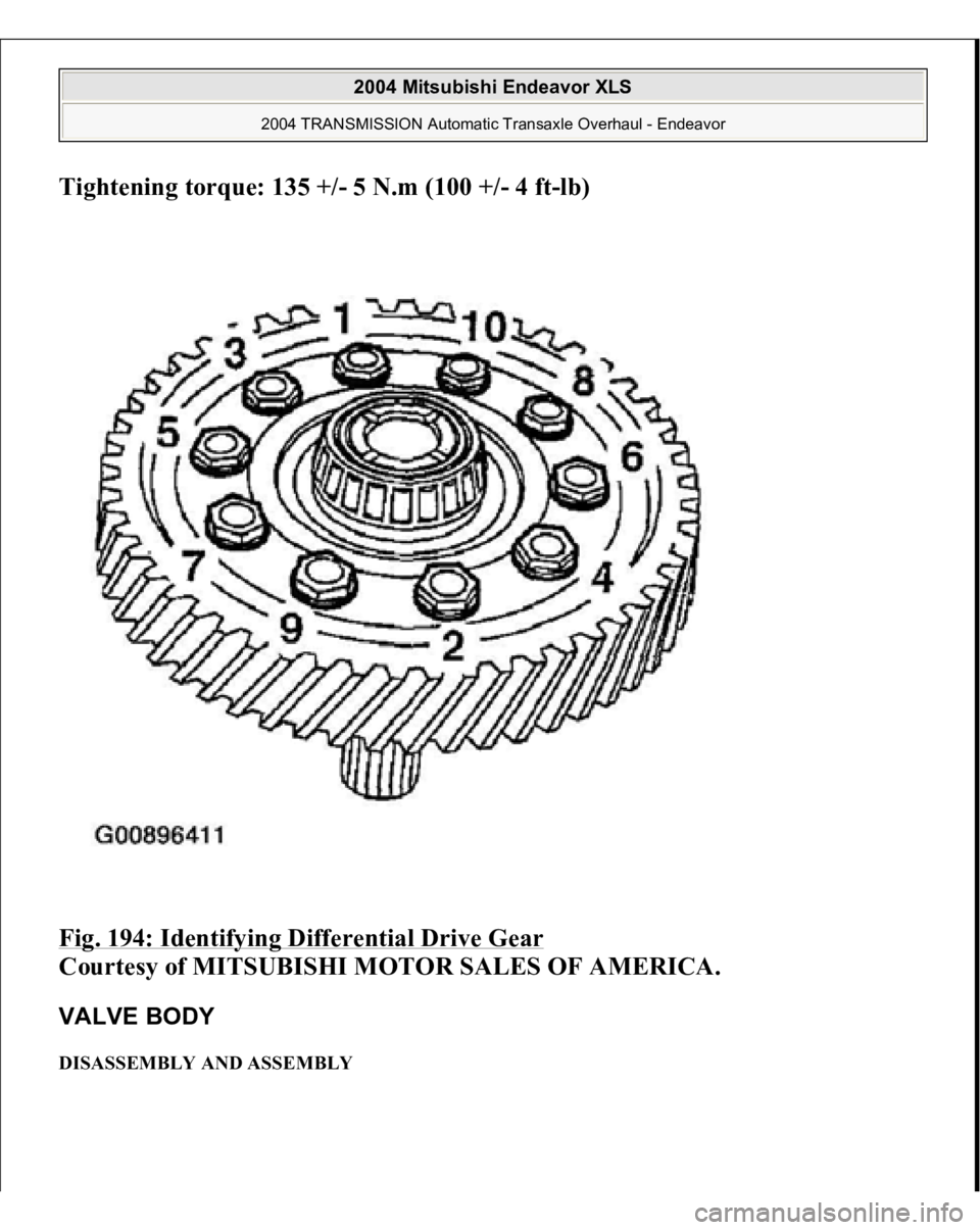
>>D<< DIFFERENTIAL DRIVE GEAR INSTALLATION Apply ATF to the bolts, and then tighten the bolts to the specified torque in the
sequence shown.
NOTE: Adjust until the backlash on both sides are equal.
2004 Mitsubishi Endeavor XLS
2004 TRANSMISSION Automatic Transaxle Overhaul - Endeavor
Page 648 of 3870
Tightening torque: 135 +/- 5 N.m (100 +/- 4 f
t-lb)
Fig. 194: Identifying Differential Drive Gear
Courtesy of MITSUBISHI MOTOR SALES OF AMERICA.
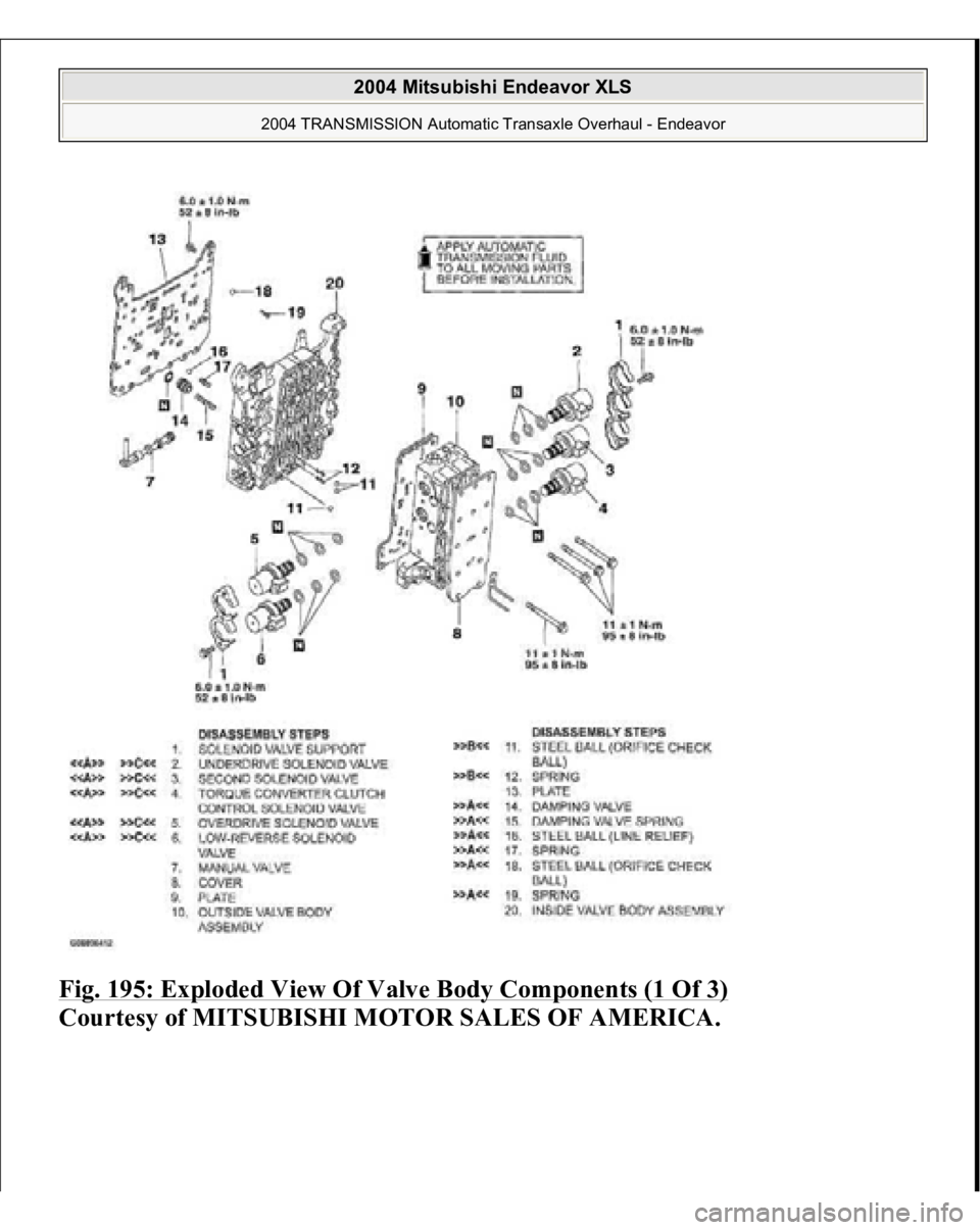
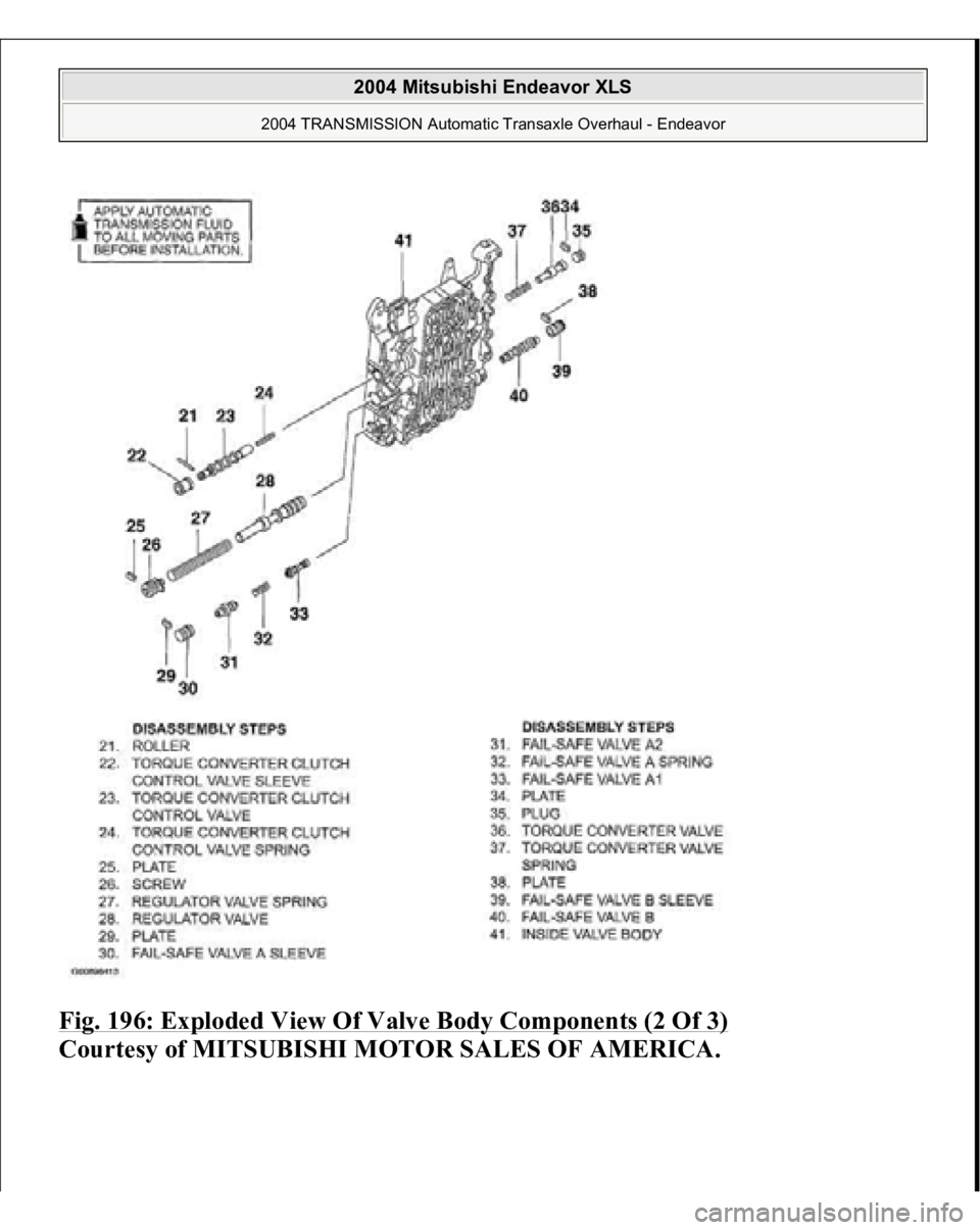
VALVE BODY DISASSEMBLY AND ASSEMBLY
2004 Mitsubishi Endeavor XLS
2004 TRANSMISSION Automatic Transaxle Overhaul - Endeavor
Page 649 of 3870
Fig. 195: Exploded View Of Valve Body Components (1 Of 3)
Courtes
y of MITSUBISHI MOTOR SALES OF AMERICA
.
2004 Mitsubishi Endeavor XLS
2004 TRANSMISSION Automatic Transaxle Overhaul - Endeavor
Page 650 of 3870
Fig. 196: Exploded View Of Valve Body Components (2 Of 3)
Courtesy of MITSUBISHI MOTOR SALES OF AMERICA.
2004 Mitsubishi Endeavor XLS
2004 TRANSMISSION Automatic Transaxle Overhaul - Endeavor
Trending: air condition compressor, key, AUX, ABS, Air conditioner, valve timing, hood open
