MITSUBISHI ENDEAVOR 2004 Service Repair Manual
ENDEAVOR 2004
MITSUBISHI
MITSUBISHI
https://www.carmanualsonline.info/img/19/57105/w960_57105-0.png
MITSUBISHI ENDEAVOR 2004 Service Repair Manual
Trending: seats, brakes, Windows, ECU, camshaft, jump start, control module
Page 611 of 3870
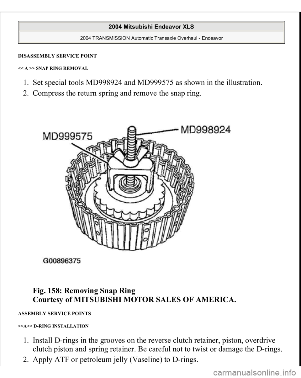
DISASSEMBLY SERVICE POINT << A >> SNAP RING REMOVAL 1. Set special tools MD998924 and MD999575 as shown in the illustration.
2. Compress the return spring and remove the snap ring.
Fig. 158: Removing Snap Ring
Courtesy of MITSUBISHI MOTOR SALES OF AMERICA.
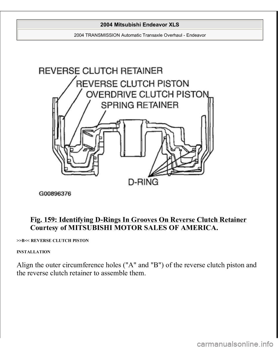
ASSEMBLY SERVICE POINTS >>A<< D-RING INSTALLATION 1. Install D-rings in the grooves on the reverse clutch retainer, piston, overdrive
clutch piston and spring retainer. Be careful not to twist or damage the D-rings.
2. A
pply ATF or
petroleum
jelly (Vaseline
) to D-rin
gs.
2004 Mitsubishi Endeavor XLS
2004 TRANSMISSION Automatic Transaxle Overhaul - Endeavor
Page 612 of 3870
Fig. 159: Identifying D
-Rings In Grooves On Reverse Clutch Retainer
Courtesy of MITSUBISHI MOTOR SALES OF AMERICA.
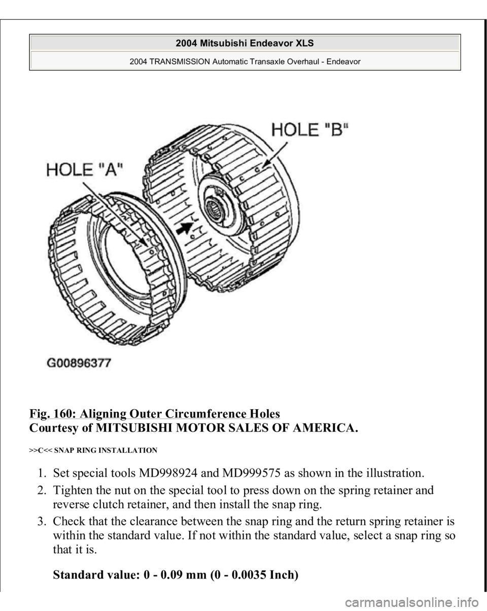
>>B<< REVERSE CLUTCH PISTON
INSTALLATION Align the outer circumference holes ("A" and "B") of the reverse clutch piston and
the reverse clutch retainer to assemble them.
2004 Mitsubishi Endeavor XLS
2004 TRANSMISSION Automatic Transaxle Overhaul - Endeavor
Page 613 of 3870
Fig. 160: Aligning Outer Circumference Holes
Courtesy of MITSUBISHI MOTOR SALES OF AMERICA.
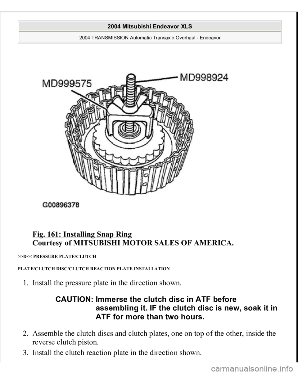
>>C<< SNAP RING INSTALLATION 1. Set special tools MD998924 and MD999575 as shown in the illustration.
2. Tighten the nut on the special tool to press down on the spring retainer and
reverse clutch retainer, and then install the snap ring.
3. Check that the clearance between the snap ring and the return spring retainer is
within the standard value. If not within the standard value, select a snap ring so
that it is.
Standard value: 0 - 0.09 mm (0 - 0.0035 Inch)
2004 Mitsubishi Endeavor XLS
2004 TRANSMISSION Automatic Transaxle Overhaul - Endeavor
Page 614 of 3870
Fig. 161: Installing Snap Ring
Courtesy of MITSUBISHI MOTOR SALES OF AMERICA.
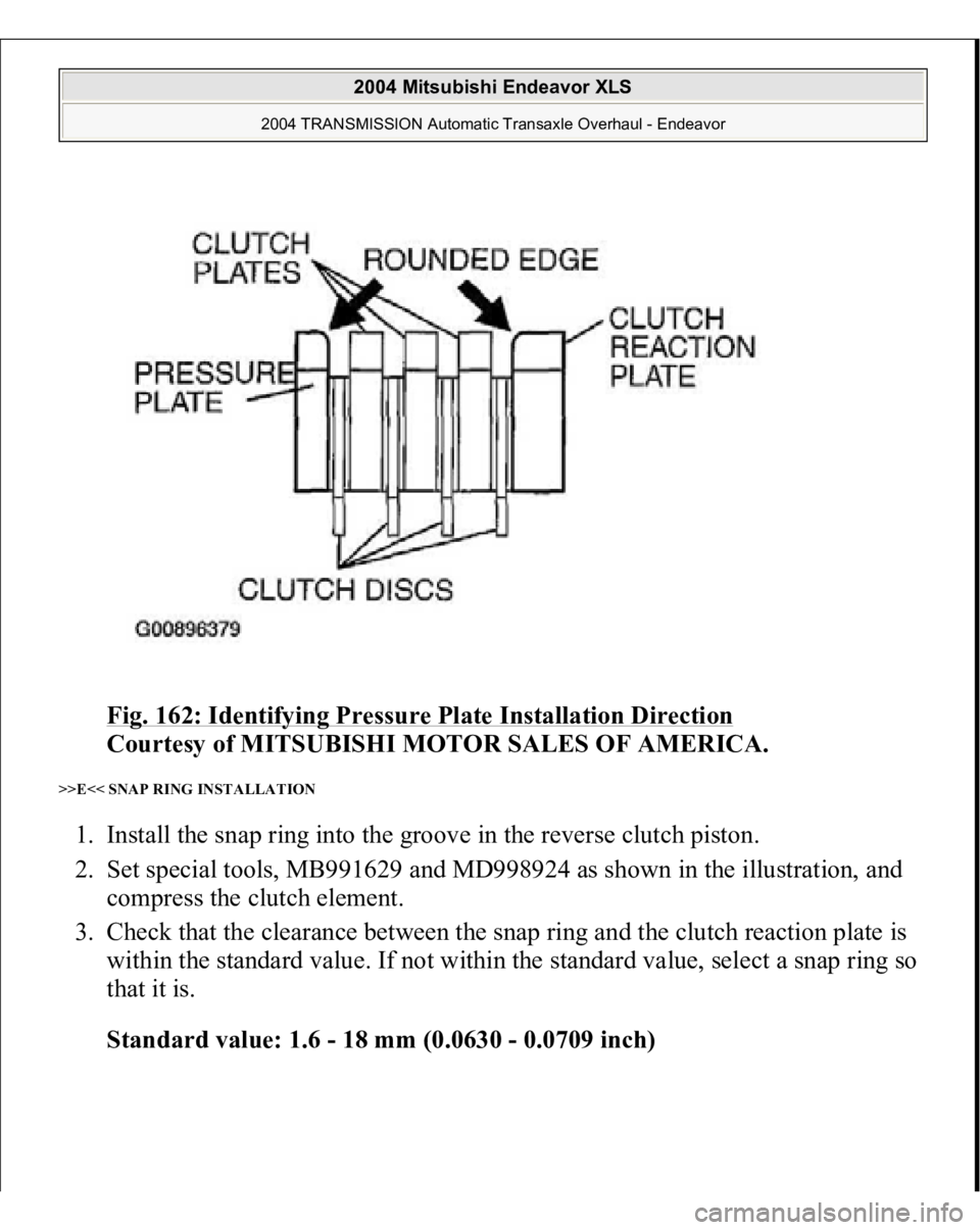
>>D<< PRESSURE PLATE/CLUTCH
PLATE/CLUTCH DISC/CLUTCH REACTION PLATE INSTALLATION 1. Install the pressure plate in the direction shown.
2. Assemble the clutch discs and clutch plates, one on top of the other, inside the
reverse clutch piston.
3. Install the clutch reaction
plate in the direction shown.
CAUTION: Immerse the clutch disc in ATF before
assembling it. IF the clutch disc is new, soak it in
ATF for more than two hours.
2004 Mitsubishi Endeavor XLS
2004 TRANSMISSION Automatic Transaxle Overhaul - Endeavor
Page 615 of 3870
Fig. 162: Identifying Pressure Plate Installation Direction
Courtesy of MITSUBISHI MOTOR SALES OF AMERICA.
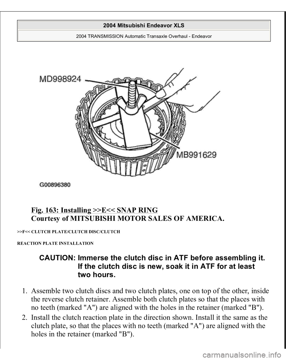
>>E<< SNAP RING INSTALLATION 1. Install the snap ring into the groove in the reverse clutch piston.
2. Set special tools, MB991629 and MD998924 as shown in the illustration, and
compress the clutch element.
3. Check that the clearance between the snap ring and the clutch reaction plate is
within the standard value. If not within the standard value, select a snap ring so
that it is.
Standard value: 1.6 - 18 mm (0.0630 - 0.0709 inch)
2004 Mitsubishi Endeavor XLS
2004 TRANSMISSION Automatic Transaxle Overhaul - Endeavor
Page 616 of 3870
Fig. 163: Installing >>E<< SNAP RING
Courtesy of MITSUBISHI MOTOR SALES OF AMERICA.
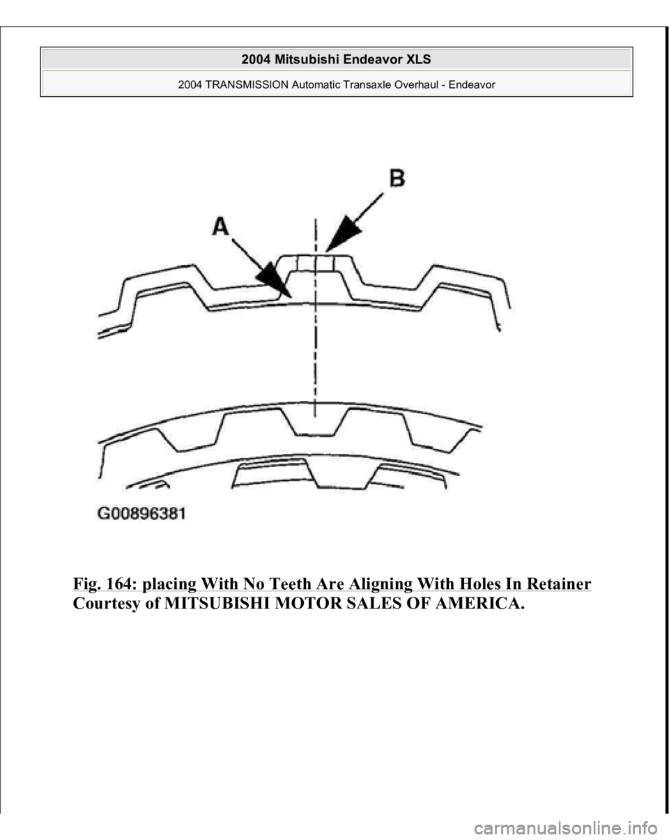
>>F<< CLUTCH PLATE/CLUTCH DISC/CLUTCH
REACTION PLATE INSTALLATION 1. Assemble two clutch discs and two clutch plates, one on top of the other, inside
the reverse clutch retainer. Assemble both clutch plates so that the places with
no teeth (marked "A") are aligned with the holes in the retainer (marked "B").
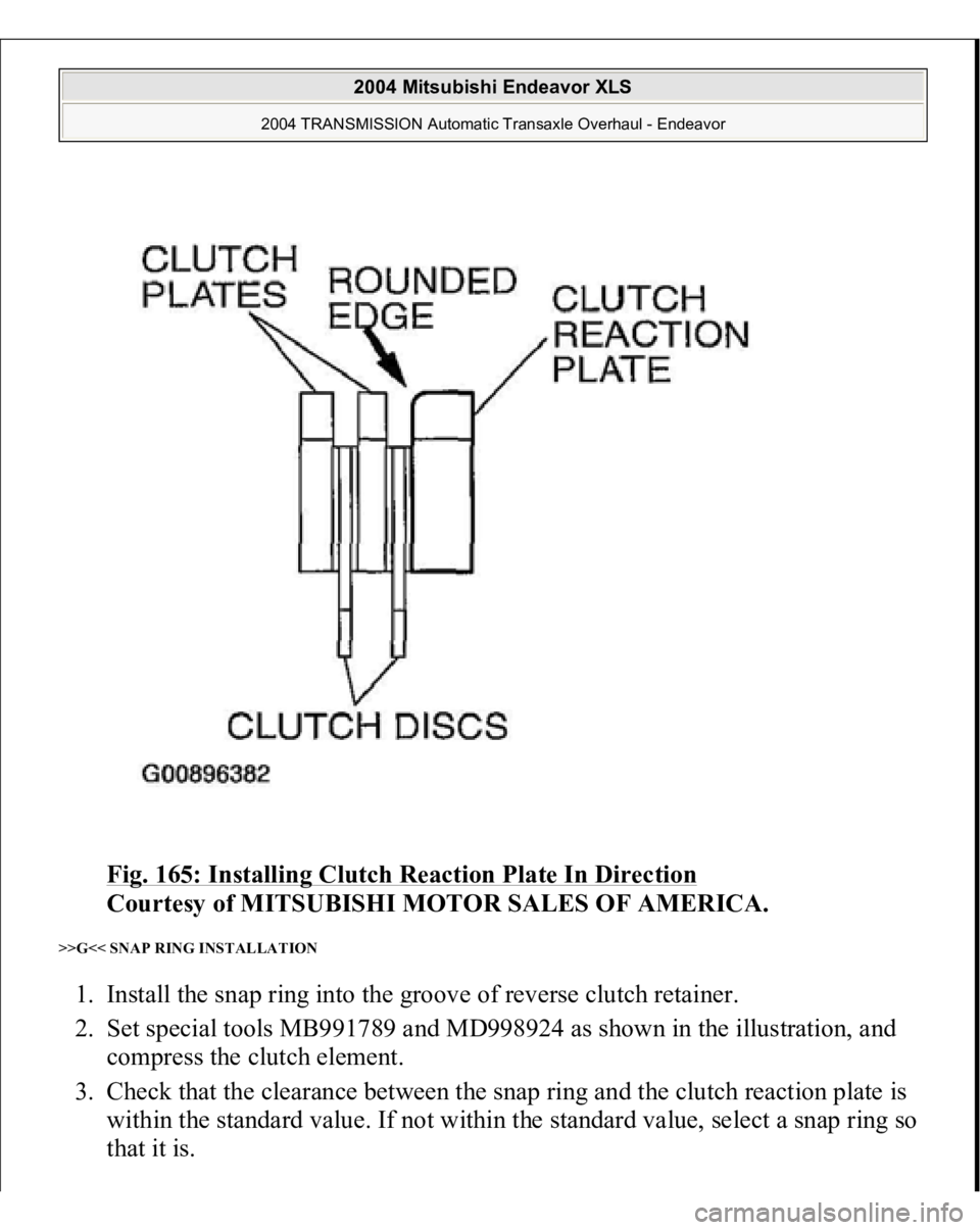
2. Install the clutch reaction plate in the direction shown. Install it the same as the
clutch plate, so that the places with no teeth (marked "A") are aligned with the
holes in the retainer (marked "B").
CAUTION: Immerse the clutch disc in ATF before assembling it.
If the clutch disc is new, soak it in ATF for at least
two hours.
2004 Mitsubishi Endeavor XLS
2004 TRANSMISSION Automatic Transaxle Overhaul - Endeavor
Page 617 of 3870
Fig. 164: placing With No Teeth Are Aligning With Holes In Retainer
Courtes
y of MITSUBISHI MOTOR SALES OF AMERICA
.
2004 Mitsubishi Endeavor XLS
2004 TRANSMISSION Automatic Transaxle Overhaul - Endeavor
Page 618 of 3870
Fig. 165: Installing Clutch Reaction Plate In Direction
Courtesy of MITSUBISHI MOTOR SALES OF AMERICA.
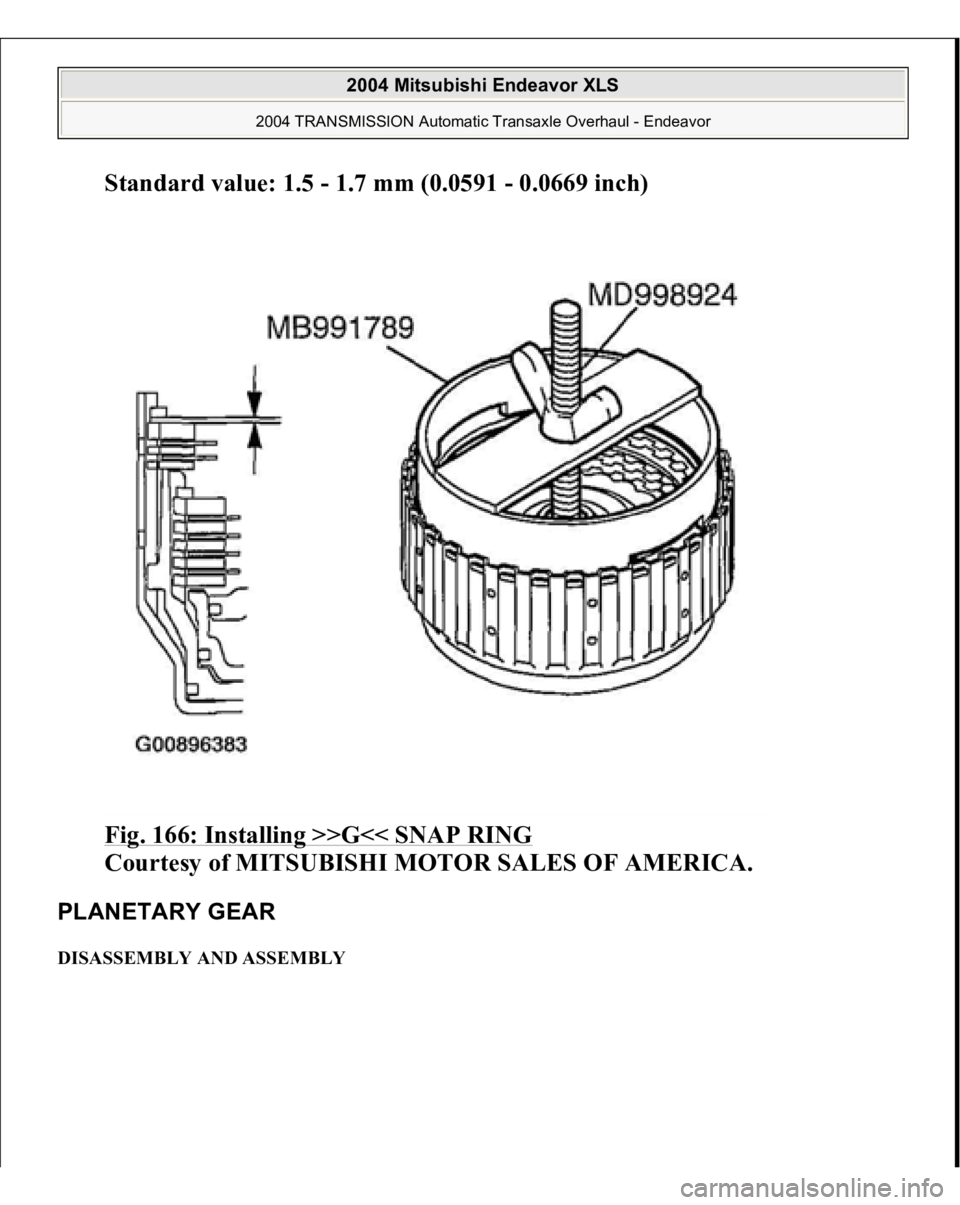
>>G<< SNAP RING INSTALLATION 1. Install the snap ring into the groove of reverse clutch retainer.
2. Set special tools MB991789 and MD998924 as shown in the illustration, and
compress the clutch element.
3. Check that the clearance between the snap ring and the clutch reaction plate is
within the standard value. If not within the standard value, select a snap ring so
that it is.
2004 Mitsubishi Endeavor XLS
2004 TRANSMISSION Automatic Transaxle Overhaul - Endeavor
Page 619 of 3870
Standard value: 1.5 - 1.7 mm (0.0591 - 0.0669 inch)
Fig. 166: Installing >>G<< SNAP RING
Courtesy of MITSUBISHI MOTOR SALES OF AMERICA.
PLANETARY GEAR DISASSEMBLY AND ASSEMBLY
2004 Mitsubishi Endeavor XLS
2004 TRANSMISSION Automatic Transaxle Overhaul - Endeavor
Page 620 of 3870
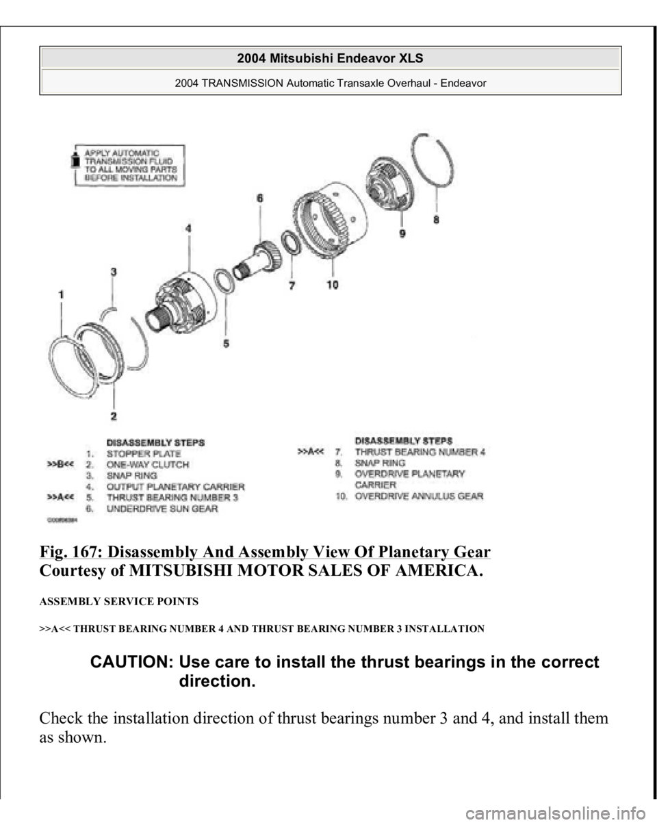
Fig. 167: Disassembly And Assembly View Of Planetary Gear
Courtesy of MITSUBISHI MOTOR SALES OF AMERICA.
ASSEMBLY SERVICE POINTS >>A<< THRUST BEARING NUMBER 4 AND THRUST BEARING NUMBER 3 INSTALLATION Check the installation direction of thrust bearings number 3 and 4, and install them
as shown.
CAUTION: Use care to install the thrust bearings in the correct
direction.
2004 Mitsubishi Endeavor XLS
2004 TRANSMISSION Automatic Transaxle Overhaul - Endeavor
Trending: module location, O2 sensor, p0340, brake pads, horn, USB, ECU
