lights MITSUBISHI ENDEAVOR 2004 Service Repair Manual
[x] Cancel search | Manufacturer: MITSUBISHI, Model Year: 2004, Model line: ENDEAVOR, Model: MITSUBISHI ENDEAVOR 2004Pages: 3870, PDF Size: 98.47 MB
Page 699 of 3870
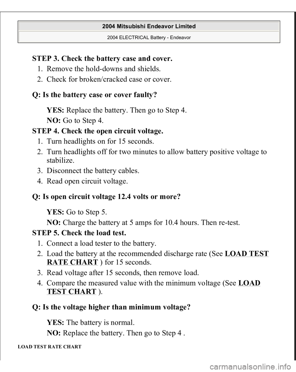
STEP 3. Check the battery case and cover.
1. Remove the hold-downs and shields.
2. Check for broken/cracked case or cover.
Q: Is the battery case or cover faulty?
YES: Replace the battery. Then go to Step 4.
NO: Go to Step 4.
STEP 4. Check the open circuit voltage.
1. Turn headlights on for 15 seconds.
2. Turn headlights off for two minutes to allow battery positive voltage to
stabilize.
3. Disconnect the battery cables.
4. Read open circuit voltage.
Q: Is open circuit voltage 12.4 volts or more?
YES: Go to Step 5.
NO: Charge the battery at 5 amps for 10.4 hours. Then re-test.
STEP 5. Check the load test.
1. Connect a load tester to the battery.
2. Load the battery at the recommended discharge rate (See LOAD TEST
RATE CHART
) for 15 seconds.
3. Read voltage after 15 seconds, then remove load.
4. Compare the measured value with the minimum voltage (See LOAD
TEST CHART
).
Q: Is the voltage higher than minimum voltage?
YES: The battery is normal.
NO: Replace the battery. Then go to Step 4 .
LOAD TEST RATE CHART
2004 Mitsubishi Endeavor Limited 2004 ELECTRICAL Battery - Endeavor
Page 1099 of 3870
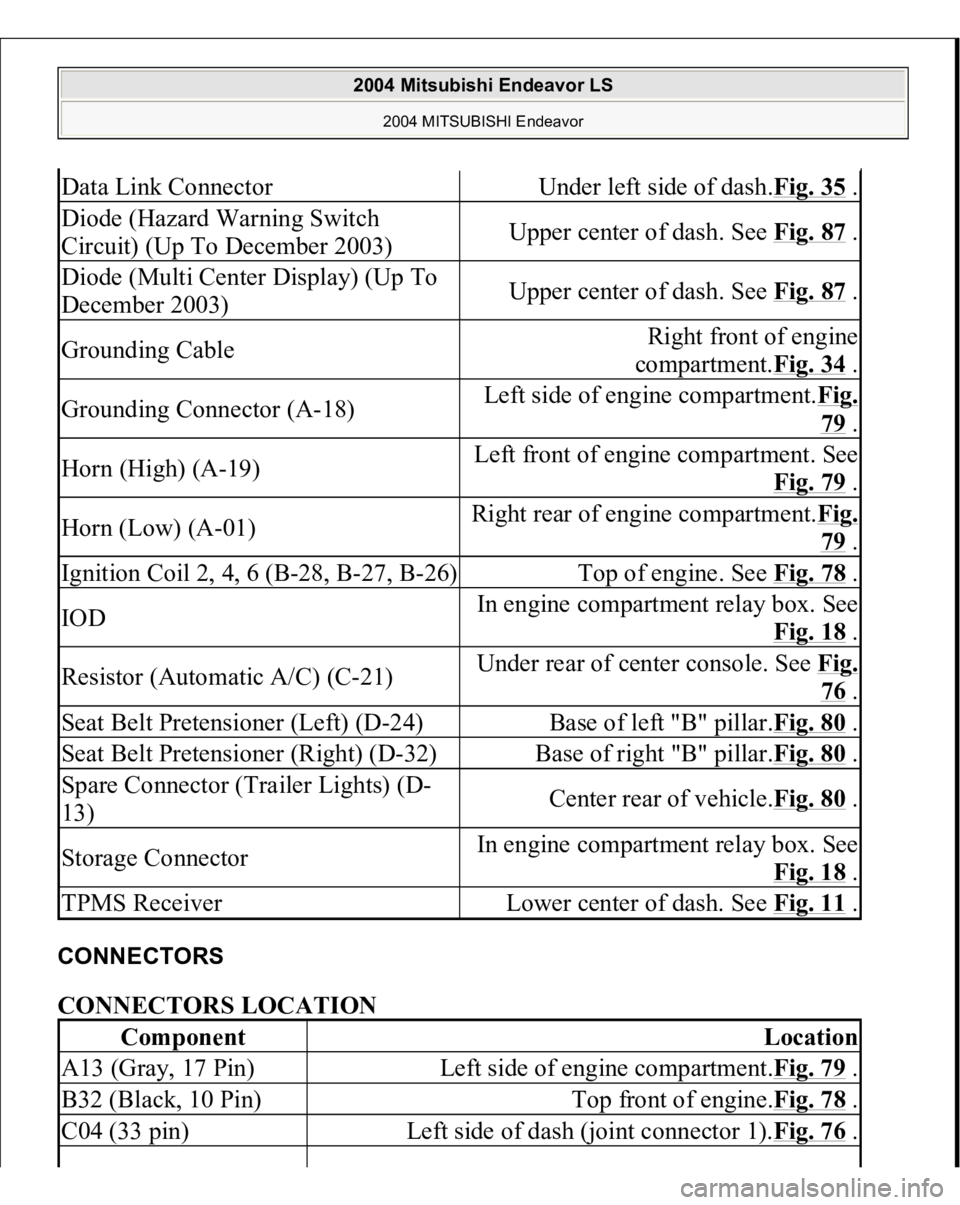
CONNECTORS CONNECTORS LOCATION Data Link Connector
Under left side of dash.Fig. 35
.
Diode (Hazard Warning Switch
Circuit) (Up To December 2003)
Upper center of dash. See Fig. 87
.
Diode (Multi Center Display) (Up To
December 2003)
Upper center of dash. See Fig. 87
.
Grounding Cable
Right front of engine
compartment.Fig. 34
.
Grounding Connector (A-18)
Left side of engine compartment.Fig.
79 .
Horn (High) (A-19)
Left front of engine compartment. See
Fig. 79
.
Horn (Low) (A-01)
Right rear of engine compartment.Fi
g.
79 .
Ignition Coil 2, 4, 6 (B-28, B-27, B-26)
Top of engine. See Fig. 78
.
IOD
In engine compartment relay box. See
Fig. 18
.
Resistor (Automatic A/C) (C-21)
Under rear of center console. See Fi
g.
76 .
Seat Belt Pretensioner (Left) (D-24)
Base of left "B" pillar.Fig. 80
.
Seat Belt Pretensioner (Right) (D-32)
Base of right "B" pillar.Fig. 80
.
Spare Connector (Trailer Lights) (D-
13)
Center rear of vehicle.Fig. 80
.
Storage Connector
In engine compartment relay box. See
Fig. 18
.
TPMS Receiver
Lower center of dash. See Fig. 11
.
Component
Location
A13 (Gray, 17 Pin)
Left side of engine compartment.Fig. 79
.
B32 (Black, 10 Pin)
Top front of engine.Fig. 78
.
C04 (33 pin)
Left side of dash (joint connector 1).Fig. 76
.
2004 Mitsubishi Endeavor LS
2004 MITSUBISHI Endeavor
Page 1271 of 3870
For belt tension, see ADJUSTMENTS
.
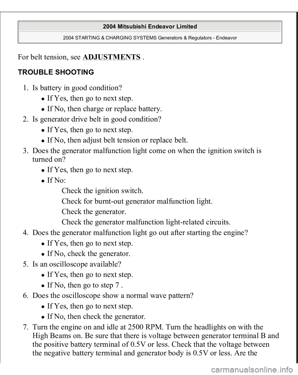
TROUBLE SHOOTING 1. Is battery in good condition?
If Yes, then go to next step. If No, then charge or replace battery.
2. Is generator drive belt in good condition? If Yes, then go to next step. If No, then adjust belt tension or replace belt.
3. Does the generator malfunction light come on when the ignition switch is
turned on? If Yes, then go to next step. If No:
Check the ignition switch.
Check for burnt-out generator malfunction light.
Check the generator.
Check the generator malfunction light-related circuits.
4. Does the generator malfunction light go out after starting the engine? If Yes, then go to next step. If No, check the generator.
5. Is an oscilloscope available? If Yes, then go to next step. If No, then go to step 7 .
6. Does the oscilloscope show a normal wave pattern? If Yes, then go to next step. If No, then check the generator.
7. Turn the engine on and idle at 2500 RPM. Turn the headlights on with the
High Beams on. Be sure that there is voltage between generator terminal B and
the positive battery terminal of 0.5V or less. Check that the voltage between
the negative batter
y terminal and
generator bod
y is 0.5V or less. Are the
2004 Mitsubishi Endeavor Limited
2004 STARTING & CHARGING SYSTEMS Generators & Regulators - Endeavor
Page 1274 of 3870
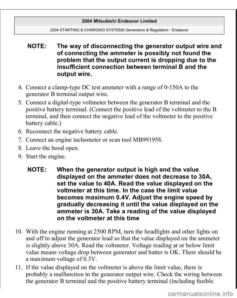
4. Connect a clamp-type DC test ammeter with a range of 0-150A to the
generator B terminal output wire.
5. Connect a digital-type voltmeter between the generator B terminal and the
positive battery terminal. (Connect the positive lead of the voltmeter to the B
terminal, and then connect the negative lead of the voltmeter to the positive
battery cable.)
6. Reconnect the negative battery cable.
7. Connect an engine tachometer or scan tool MB991958.
8. Leave the hood open.
9. Start the engine.
10. With the engine running at 2500 RPM, turn the headlights and other lights on
and off to adjust the generator load so that the value displayed on the ammeter
is slightly above 30A. Read the voltmeter. Voltage reading at or below limit
value means voltage drop between generator and batter is OK. There should be
a maximum voltage of 0.3V.
11. If the value displayed on the voltmeter is above the limit value, there is
probably a malfunction in the generator output wire. Check the wiring between
the
generator B terminal and the
positive batter
y terminal
(includin
g fusible
NOTE: The way of disconnecting the generator output wire and
of connecting the ammeter is possibly not found the
problem that the output current is dropping due to the
insufficient connection between terminal B and the
output wire.
NOTE: When the generator output is high and the value
displayed on the ammeter does not decrease to 30A,
set the value to 40A. Read the value displayed on the
voltmeter at this time. In the case the limit value
becomes maximum 0.4V. Adjust the engine speed by
gradually decreasing it until the value displayed on the
ammeter is 30A. Take a reading of the value displayed
on the voltmeter at this time
2004 Mitsubishi Endeavor Limited
2004 STARTING & CHARGING SYSTEMS Generators & Regulators - Endeavor
Page 1275 of 3870
link). If a terminal is not sufficiently tight or if the harness has become
discolored due to overheating, repair and then test again.
12. After the test, run the engine at idle.
13. Turn off all lights and turn the ignition switch to the LOCK (OFF) position.
14. Disconnect the negative battery cable.
15. Disconnect the ammeter and voltmeter.
16. Connect the negative battery cable.
17. Run engine for 10 minutes at an idle.
OUTPUT CURRENT TEST Required special tool: MB991958: Scan Tool MUT-III Sub Assembly, MB991824:
V.C.I., MB991827 MUT-III USB Cable, MB5991910: MUT-III Main Harness A.
This test determines whether the generator outputs normal current. For best results,
use a char
ging system tester. If not available, follow the ste
ps below. See Fig. 4
.
2004 Mitsubishi Endeavor Limited
2004 STARTING & CHARGING SYSTEMS Generators & Regulators - Endeavor
Page 1278 of 3870
11. Immediately after setting the headlights to high beam and turning the heater
blower switch to the highest position, increase the engine speed to 2,500 RPM
and read the maximum current output value displayed on the ammeter. Limit
value: 70 percent of nominal current output.
12. The reading on the ammeter should be above the limit value. If the reading is
below the limit value and the generator output wire is normal, remove the
generator from the engine and check the generator.
13. Run the engine at idle speed after the test.
14. Turn the ignition switch to the LOCK (OFF) position.
15. Disconnect the engine tachometer or scan tool MB991958.
16. Disconnect the negative battery cable.
17. Disconnect the ammeter and voltmeter.
18. Connect the negative battery cable.
19. Run the engine for 10 minutes at an idle. REGULATED VOLTAGE TEST Required special tools:
MB991958: Scan Tool MUT
-III Sub Assembly.
NOTE: The current output value will depend on the electrical
load and the temperature of the generator body.
NOTE: If the electrical load is small while testing, the specified
level of current may not be output even though the
generator is normal. In such cases, increase the
electrical load by leaving the headlights turned on for
some time to discharge the battery or by using the
lighting system in another vehicle, and then test again.
NOTE: The specified level of current also may not be output if
the temperature of the generator body or the ambient
temperature is too high. In such cases, cool the
generator and then test again.
2004 Mitsubishi Endeavor Limited
2004 STARTING & CHARGING SYSTEMS Generators & Regulators - Endeavor
Page 1280 of 3870
Generator installation. Check to be sure that the battery installed in the vehicle is fully charged. Generator drive belt tension. Fusible link. Abnormal noise from the generator while the engine is running.
2. Turn the ignition switch to the LOCK (OFF) position.
3. Disconnect the negative battery cable.
4. Use the special tool (Generator Harness Connector: MB991519) to connect a
digital-type voltmeter between the generator S terminal and ground. (Connect
the positive lead of the voltmeter to the S terminal, and then connect the
negative lead of the voltmeter to a secure ground or to the negative battery
terminal.)
5. Connect a clamp-type DC test ammeter with a range of 0-150A to the
generator B terminal output wire.
6. Reconnect the negative battery cable.
7. Connect an engine tachometer, or scan tool MB991958.
8. Turn the ignition switch to the ON position and check that the reading on the
voltmeter is equal to the battery positive voltage.
9. Check to be sure that all lights and accessories are off.
10. Start the engine.
11. Increase the engine speed to 2,500 RPM
12. Read the value displayed on the voltmeter when the current output by the
generator becomes 10A or less.
13. If the voltage reading conforms to the value in the voltage regulation table,
then the voltage regulator is operating normally. If the voltage is outside the
standard value, there is a malfunction of the volta
ge re
gulator or the
generator.
NOTE: If the voltage is 0V, the cause is probably an open
circuit in the wire or fusible link between the generator
S terminal and the battery positive terminal or
malfunctioning voltmeter.
2004 Mitsubishi Endeavor Limited
2004 STARTING & CHARGING SYSTEMS Generators & Regulators - Endeavor
Page 1281 of 3870
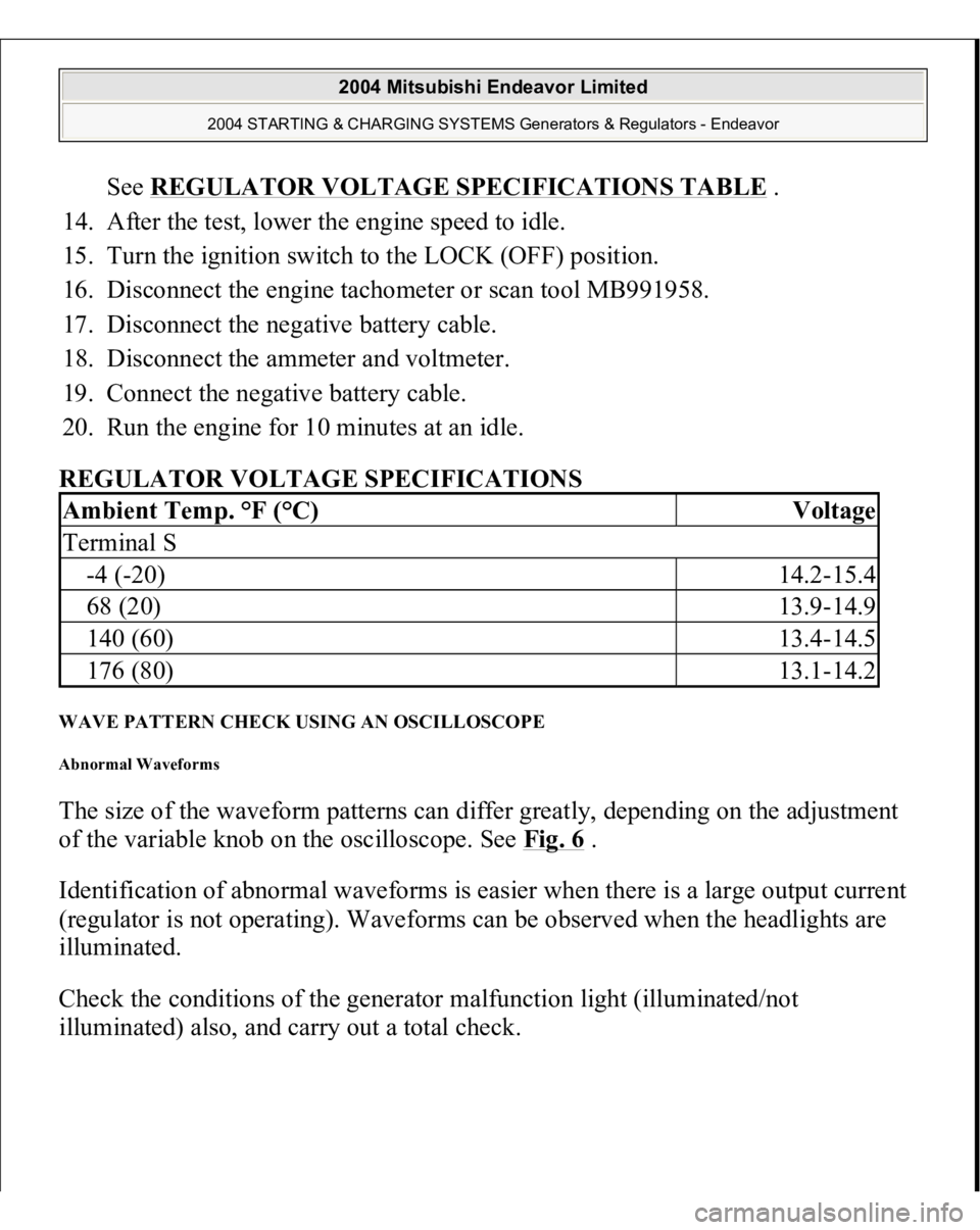
See REGULATOR VOLTAGE SPECIFICATIONS TABLE
.
14. After the test, lower the engine speed to idle.
15. Turn the ignition switch to the LOCK (OFF) position.
16. Disconnect the engine tachometer or scan tool MB991958.
17. Disconnect the negative battery cable.
18. Disconnect the ammeter and voltmeter.
19. Connect the negative battery cable.
20. Run the engine for 10 minutes at an idle.
REGULATOR VOLTAGE SPECIFICATIONS
WAVE PATTERN CHECK USING AN OSCILLOSCOPE Abnormal Waveforms The size of the waveform patterns can differ greatly, depending on the adjustment
of the variable knob on the oscilloscope. See Fig. 6
.
Identification of abnormal waveforms is easier when there is a large output current
(regulator is not operating). Waveforms can be observed when the headlights are
illuminated.
Check the conditions of the generator malfunction light (illuminated/not
illuminated
) also, and carr
y out a total check.
Ambient Temp. °F (°C)
Voltage
Terminal S-4 (-20)
14.2-15.4
68 (20)
13.9-14.9
140 (60)
13.4-14.5
176 (80)
13.1-14.2
2004 Mitsubishi Endeavor Limited
2004 STARTING & CHARGING SYSTEMS Generators & Regulators - Endeavor
Page 1516 of 3870
Required Special Tool
:
MB991958: Scan Tool (MUT-III Sub Assembly)
MB991824: V.C.I. MB991827: MUT-III USB Cable MB991910: MUT-III Main Harness A
1. Before checks set the vehicle in the following condition:
Engine coolant temperature: 80 - 95°C (176 - 203°F) Lights and all accessories: OFF Transaxle: P range
2. Connect scan tool MB991958 to the data link connec
tor.
NOTE: Vehicles for Canada, the headlight, taillight, etc. remain
lit even when the lighting switch is in "OFF" position
but this is no problem for checks.
CAUTION: To prevent damage to scan tool MB991958,
always turn the ignition switch to the
"LOCK" (OFF) position before connecting or
disconnecting scan tool MB991958.
2004 Mitsubishi Endeavor Limited
2004 ENGINE Engine - Endeavor
Page 1519 of 3870
MB991958: Scan Tool (MUT-III Sub Assembly)
MB991824: V.C.I. MB991827: MUT-III USB Cable MB991910: MUT-III Main Harness A
1. Before checks set the vehicle in the following condition:
Engine coolant temperature: 80 - 95°C (176 - 203°F) Lights and all accessories: OFF Transaxle: P range
2. Connect scan tool MB991958 to the data link connec
tor.
NOTE: Vehicles for Canada, the headlight, taillight, etc. remain
lit even when the lighting switch is in "OFF" position
but this is no problem for checks.
CAUTION: To prevent damage to scan tool MB991958,
always turn the ignition switch to the
"LOCK" (OFF) position before connecting or
disconnecting scan tool MB991958.
2004 Mitsubishi Endeavor Limited
2004 ENGINE Engine - Endeavor