fuse MITSUBISHI ENDEAVOR 2004 Service Repair Manual
[x] Cancel search | Manufacturer: MITSUBISHI, Model Year: 2004, Model line: ENDEAVOR, Model: MITSUBISHI ENDEAVOR 2004Pages: 3870, PDF Size: 98.47 MB
Page 186 of 3870
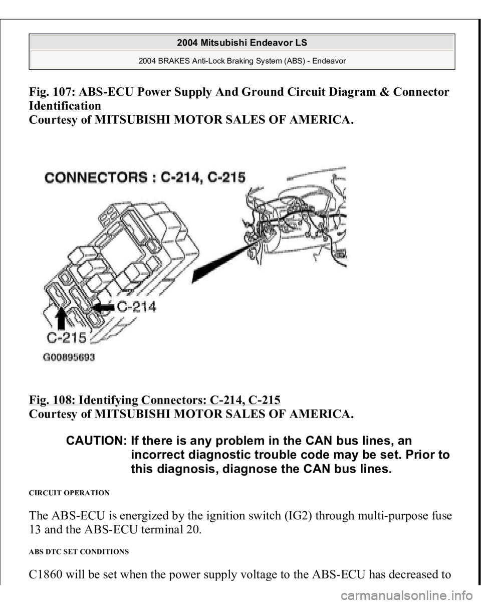
Fig. 107: ABS
-ECU Power Supply And Ground Circuit Diagram & Connector
Identification
Courtesy of MITSUBISHI MOTOR SALES OF AMERICA.
Fig. 108: Identifying Connectors: C
-214, C
-215
Courtesy of MITSUBISHI MOTOR SALES OF AMERICA.
CIRCUIT OPERATION The ABS-ECU is energized by the ignition switch (IG2) through multi-purpose fuse
13 and the ABS-ECU terminal 20. ABS DTC SET CONDITIONS C1860 will be set when the
power su
pply volta
ge to the AB
S-ECU has decreased to
CAUTION: If there is any problem in the CAN bus lines, an
incorrect diagnostic trouble code may be set. Prior to
this diagnosis, diagnose the CAN bus lines.
2004 Mitsubishi Endeavor LS
2004 BRAKES Anti-Lock Braking System (ABS) - Endeavor
Page 217 of 3870
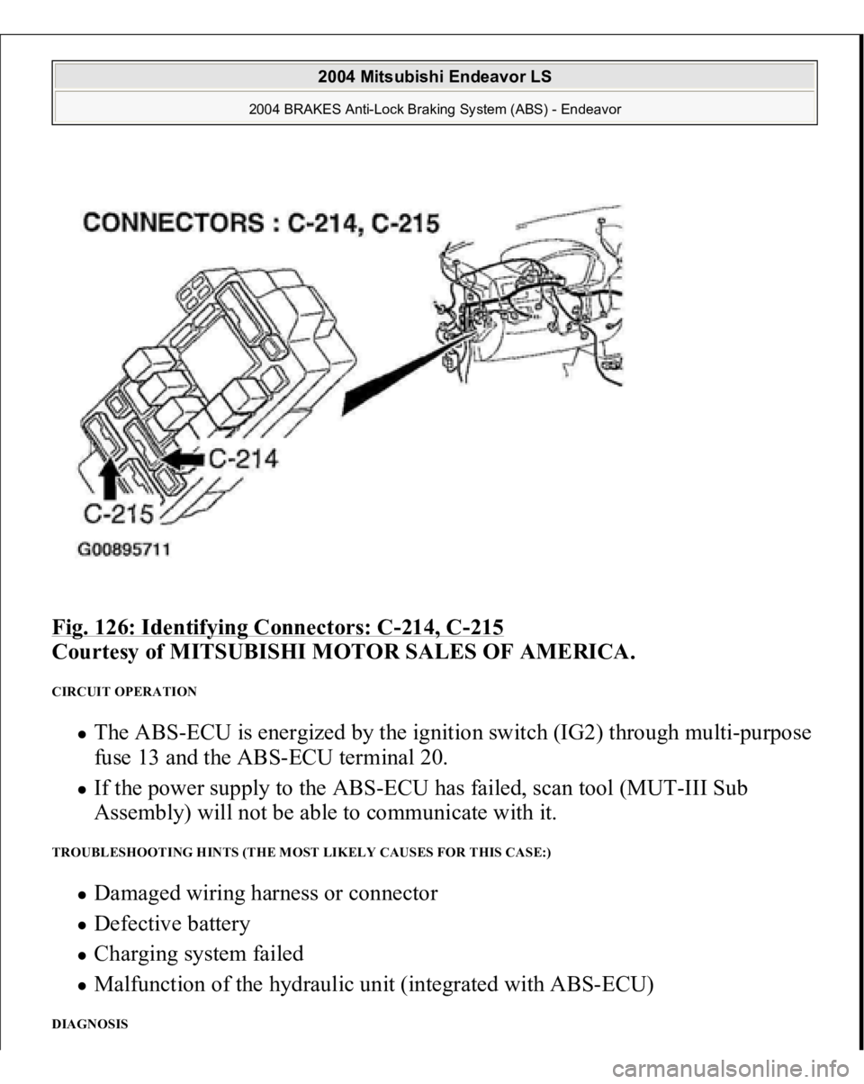
Fig. 126: Identifying Connectors: C
-214, C
-215
Courtesy of MITSUBISHI MOTOR SALES OF AMERICA.
CIRCUIT OPERATION
The ABS-ECU is energized by the ignition switch (IG2) through multi-purpose
fuse 13 and the ABS-ECU terminal 20. If the power supply to the ABS-ECU has failed, scan tool (MUT-III Sub
Assembly) will not be able to communicate with it.
TROUBLESHOOTING HINTS (THE MOST LIKELY CAUSES FOR THIS CASE:)
Damaged wiring harness or connector Defective battery Charging system failed Malfunction of the hydraulic unit (integrated with ABS-ECU)
DIAGNOSIS
2004 Mitsubishi Endeavor LS
2004 BRAKES Anti-Lock Braking System (ABS) - Endeavor
Page 277 of 3870
Such shorts can damage fuses or components and may cause a second
Diagnostic Trouble Code (DTC) to set, making diagnosis of original problem
more difficult. Never use an analog volt/ohm meter or test light in place of a Digital Volt/Ohm
Meter (DVOM). Use only a DVOM with a maximum test current of 2 mA
(milliamps) at minimum range of resistance measurement. If SRS is not fully functional for any reason, DO NOT drive vehicle until
system is repaired and fully functional. DO NOT remove bulbs, modules,
sensors, or other components or in any way disable system from operating
normally. If SRS is not functional, park vehicle until repairs are made.
DISABLING & ACTIVATING AIR BAG SYSTEM To disable system, turn ignition off. Disconnect negative battery cable. Shield cable
end with electrical tape. Wait at least 60 seconds before servicing air bag system.
To activate system, reconnect negative battery cable. Check system operation. See SYSTEM OPERATION CHECK
.
DISPOSAL PROCEDURES DEPLOYED AIR BAG OR SEAT BELT PRETENSIONER Place deployed component in a strong plastic bag and seal tightly. Dispose of
component as you would any other part. No other special disposal procedure is
required. UNDEPLOYED AIR BAG OR SEAT BELT PRETENSIONER
WARNING:Accidental air bag deployment is possible. Personal
injury may result. Read and follow all WARNINGS
and AIR BAG SAFETY PRECAUTIONS
before
working on air bag system or related components.
NOTE: Undeployed air bag modules must be deployed before
disposal. Disposing of an undeployed air bag may violate
federal, state and/or local laws. This also applies to vehicles
that are to be scrapped.
2004 Mitsubishi Endeavor Limited
2004 ACCESSORIES/SAFETY EQUIPMENT Mitsubishi - Air Bag Restraint Systems
Page 303 of 3870
1A
Driver-side front impact sensor short circuit
1B
Driver-side front impact sensor open circuit
1C
Driver-side front impact sensor short to voltage
1D
Driver-side front impact sensor short to ground
2A
Passenger-side front impact sensor short circuit
2B
Passenger-side front impact sensor open circuit
2C
Passenger-side front impact sensor short to voltage
2D
Passenger-side front impact sensor short to ground
11
Front impact sensor short circuit
12
Front impact sensor either circuit open/no power
13
Front impact sensor both circuits open/no power
14
Analog "G" sensor system
15
Safing "G" sensor short circuit
16
Safing "G" sensor open circuit
17
Safing "G" side impact sensor
21
Driver-side air bag module short circuit
22
Driver-side air bag module open circuit
24
Passenger-side air bag module short circuit
25
Passenger-side air bag module open circuit
26
Driver-side seat belt pretensioner short circuit
27
Driver-side seat belt pretensioner open circuit
28
Passenger-side seat belt pretensioner short circuit
29
Passenger-side seat belt pretensioner open circuit
31 & 32
SRS ECU capacitor circuit
34
SRS ECU connector lock circuit
35
SRS ECU air bag system deployment
41
SRS ECU power circuit (Fuse No. 2)
42
SRS ECU power circuit (Fuse No. 3)
43
AIR BAG warning light does not illuminate
43
AIR BAG warning light stays illuminated
44
AIR BAG warning light
2004 Mitsubishi Endeavor Limited
2004 ACCESSORIES/SAFETY EQUIPMENT Mitsubishi - Air Bag Restraint Systems
Page 326 of 3870
3. Reconnect all SRS components. Using scan tool, erase then retrieve DTCs. If
DTC 34 is retrieved, go to step 1 . If DTC 34 is not retrieved, system is normal
at this time. Intermittent condition may exist. DTC 35: SRS ECU AIR BAG DEPLOYMENT If DTC 35 is present, replace SRS ECU. See SRS ELECTRONIC CONTROL UNIT (SRS ECU)
under REMOVAL & INSTALLATION.
DTC 41: IG1 POWER CIRCUIT 1. Before proceeding, see AIR BAG SAFETY PRECAUTIONS
. Disable air
bag system. See DISABLING & ACTIVATING AIR BAG SYSTEM
.
Inspect fuse No. 23 in driver-side junction block, located on left side of
instrument panel. If fuse is okay, go to next step. If fuse is not okay, go to step
4 .
2. Disconnect negative battery cable. Disconnect SRS ECU connector C-26. See
SRS ELECTRONIC CONTROL UNIT (SRS ECU)
under REMOVAL &
INSTALLATION. See Fig. 19
. Connect negative battery cable. Turn ignition
on. Measure voltage between ground and SRS ECU connector C-26, terminal
No. 16 (Black/Yellow wire). See Fig. 21
. If voltage is less than 9 volts, go to
next step. If voltage is 9 volts or more, erase then retrieve DTCs using scan
tool. If DTC 41 is retrieved, replace SRS ECU. Go to step 10 .
3. Check wire harness between SRS ECU connector C-26, terminal No. 16 and
ignition switch connector C-308, terminal No. 2, including connectors C-211
and C-215. See Fig. 22
. If wire harness or connectors are damaged, replace
wire harness. Go to step 10 . If wire harness and connectors are okay, go to
step 10 .
4. Replace fuse. Turn ignition on for at least one minute, then off. Inspect fuse. If
fuse is okay, go to step 10 . If fuse is not okay, go to next step.
5. Disconnect connector C-211 from junction block. Check for continuity
between ground and connector C-211, terminal No. 24 (Black/Yellow wire).
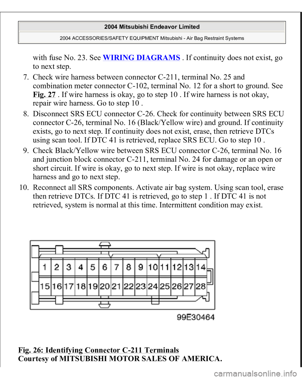
See Fig. 26
. If continuity exists, go to next step. If continuity does not exist,
go to step 8 .
6. Check for continuity between ground and terminal No. 25 (Black/White wire)
of connector C-211. If continuit
y does not exist
, check other circuits associated
2004 Mitsubishi Endeavor Limited
2004 ACCESSORIES/SAFETY EQUIPMENT Mitsubishi - Air Bag Restraint Systems
Page 327 of 3870
with fuse No. 23. See WIRING DIAGRAMS
. If continuity does not exist, go
to next step.
7. Check wire harness between connector C-211, terminal No. 25 and
combination meter connector C-102, terminal No. 12 for a short to ground. See
Fig. 27
. If wire harness is okay, go to step 10 . If wire harness is not okay,
repair wire harness. Go to step 10 .
8. Disconnect SRS ECU connector C-26. Check for continuity between SRS ECU
connector C-26, terminal No. 16 (Black/Yellow wire) and ground. If continuity
exists, go to next step. If continuity does not exist, erase, then retrieve DTCs
using scan tool. If DTC 41 is retrieved, replace SRS ECU. Go to step 10 .
9. Check Black/Yellow wire between SRS ECU connector C-26, terminal No. 16
and junction block connector C-211, terminal No. 24 for damage or an open or
short circuit. If wire is okay, go to next step. If wire is not okay, replace wire
harness and go to next step.
10. Reconnect all SRS components. Activate air bag system. Using scan tool, erase
then retrieve DTCs. If DTC 41 is retrieved, go to step 1 . If DTC 41 is not
retrieved, system is normal at this time. Intermittent condition may exist.
Fig. 26: Identifying Connector C
-211 Terminals
Courtesy of MITSUBISHI MOTOR SALES OF AMERICA.
2004 Mitsubishi Endeavor Limited
2004 ACCESSORIES/SAFETY EQUIPMENT Mitsubishi - Air Bag Restraint Systems
Page 328 of 3870
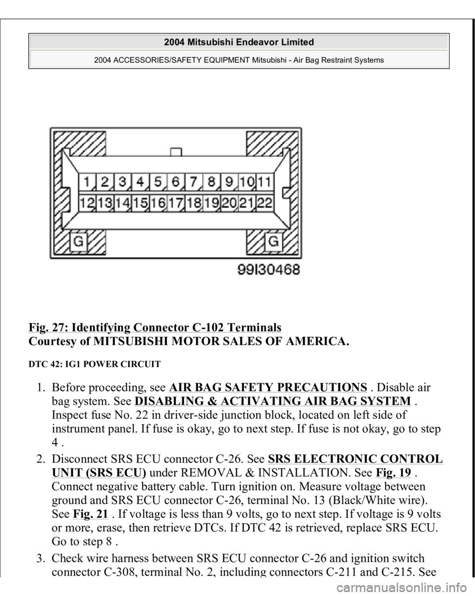
Fig. 27: Identifying Connector C
-102 Terminals
Courtesy of MITSUBISHI MOTOR SALES OF AMERICA.
DTC 42: IG1 POWER CIRCUIT 1. Before proceeding, see AIR BAG SAFETY PRECAUTIONS
. Disable air
bag system. See DISABLING & ACTIVATING AIR BAG SYSTEM
.
Inspect fuse No. 22 in driver-side junction block, located on left side of
instrument panel. If fuse is okay, go to next step. If fuse is not okay, go to step
4 .
2. Disconnect SRS ECU connector C-26. See SRS ELECTRONIC CONTROL
UNIT (SRS ECU)
under REMOVAL & INSTALLATION. See Fig. 19
.
Connect negative battery cable. Turn ignition on. Measure voltage between
ground and SRS ECU connector C-26, terminal No. 13 (Black/White wire).
See Fig. 21
. If voltage is less than 9 volts, go to next step. If voltage is 9 volts
or more, erase, then retrieve DTCs. If DTC 42 is retrieved, replace SRS ECU.
Go to step 8 .
3. Check wire harness between SRS ECU connector C-26 and ignition switch
connector C-308
, terminal No. 2
, includin
g connectors C-211 and C-215. See
2004 Mitsubishi Endeavor Limited
2004 ACCESSORIES/SAFETY EQUIPMENT Mitsubishi - Air Bag Restraint Systems
Page 329 of 3870
Fig. 22
. If wire harness and connectors are damaged, replace wire harness. Go
to step 8 . If wire harness and connectors are okay, go to step 8 .
4. Replace fuse. Turn ignition on for at least one minute, then off. Inspect fuse. If
fuse is okay, go to step 8 . If fuse is not okay, go to next step.
5. Disconnect connector C-211 from junction block. Check for continuity
between ground and terminal No. 7 (Yellow/Black wire) of connector C-211. I
f
continuity exists, check all circuits associated with fuse No. 3 for a short to
ground. If continuity does not exist, go to next step.
6. Disconnect SRS ECU connector C-26. Check for continuity between SRS ECU
connector C-26, terminal No. 13 (Black/White wire) and ground. If continuity
exists, go to next step. If continuity does not exist, erase, then retrieve DTCs
using scan tool. If DTC 42 is retrieved, replace SRS ECU. Go to step 8 .
7. Check Black/White wire between SRS ECU connector C-26, terminal No. 13
and junction block connector C-205, terminal No. 7 for an open, short or
damage. If wire is okay, go to next step. If wire is not okay, replace wire
harness and go to next step.
8. Reconnect all SRS components. Activate air bag system. Using scan tool, erase
then retrieve DTCs. If DTC 42 is retrieved, go to step 1 . If DTC 42 is not
retrieved, system is normal at this time. Intermittent condition may exist.
DTC 43: AIR BAG WARNING LIGHT DOES NOT ILLUMINATE 1. Before proceeding, see AIR BAG SAFETY PRECAUTIONS
. Disable air
bag system. See DISABLING & ACTIVATING AIR BAG SYSTEM
.
Disconnect SRS ECU connector C-26. See SRS ELECTRONIC CONTROL
UNIT (SRS ECU)
under REMOVAL & INSTALLATION. See Fig. 19
.
Connect negative battery cable. Turn ignition on. If AIR BAG warning light
does not illuminate, go to next step. If AIR BAG warning light illuminates, go
to step 3 .
2. Inspect wire harness between ignition switch connector C-308 and SRS ECU
connector C-26 and between C-26 and combination meter connector C-102 for
damage, a short or open circuit. If wire harness is okay, replace combination
meter assembly. Go to next step. If wire harness is not okay, replace wire
harness. Go to next step.
3. Reconnect all SRS com
ponents. Activate air ba
g system. Usin
g scan tool, erase
2004 Mitsubishi Endeavor Limited
2004 ACCESSORIES/SAFETY EQUIPMENT Mitsubishi - Air Bag Restraint Systems
Page 394 of 3870
1. Connect scan tool to Data Link Connector (DLC). See INITIAL SRS
DIAGNOSTIC PROCEDURE
under DIAGNOSTICS. If scan tool is able to
diagnose CAN bus lines and CAN bus lines are satisfactory, go to next step. If
scan tool cannot diagnose CAN bus lines, repair CAN bus lines. Go to next
step.
2. Erase, then retrieve DTCs. If DTC B1475 is retrieved, replace SRS ECU. See
SRS ELECTRONIC CONTROL UNIT (SRS ECU)
under REMOVAL &
INSTALLATION. If DTC B1475 is not retrieved, an intermittent condition
may exist.
DTCB1476: POWER SUPPLY VOLTAGE DROPS ABNORMALLY 1. Connect scan tool to Data Link Connector (DLC). See INITIAL SRS
DIAGNOSTIC PROCEDURE
under DIAGNOSTICS. If scan tool is able to
diagnose CAN bus lines and CAN bus lines are satisfactory, go to next step. If
scan tool cannot diagnose CAN bus lines, repair CAN bus lines. Go to next
step.
2. Erase, then retrieve DTCs. Turn ignition off. If DTC B1476 is retrieved, go to
next step. If DTC B1476 is not retrieved, an intermittent condition may exist.
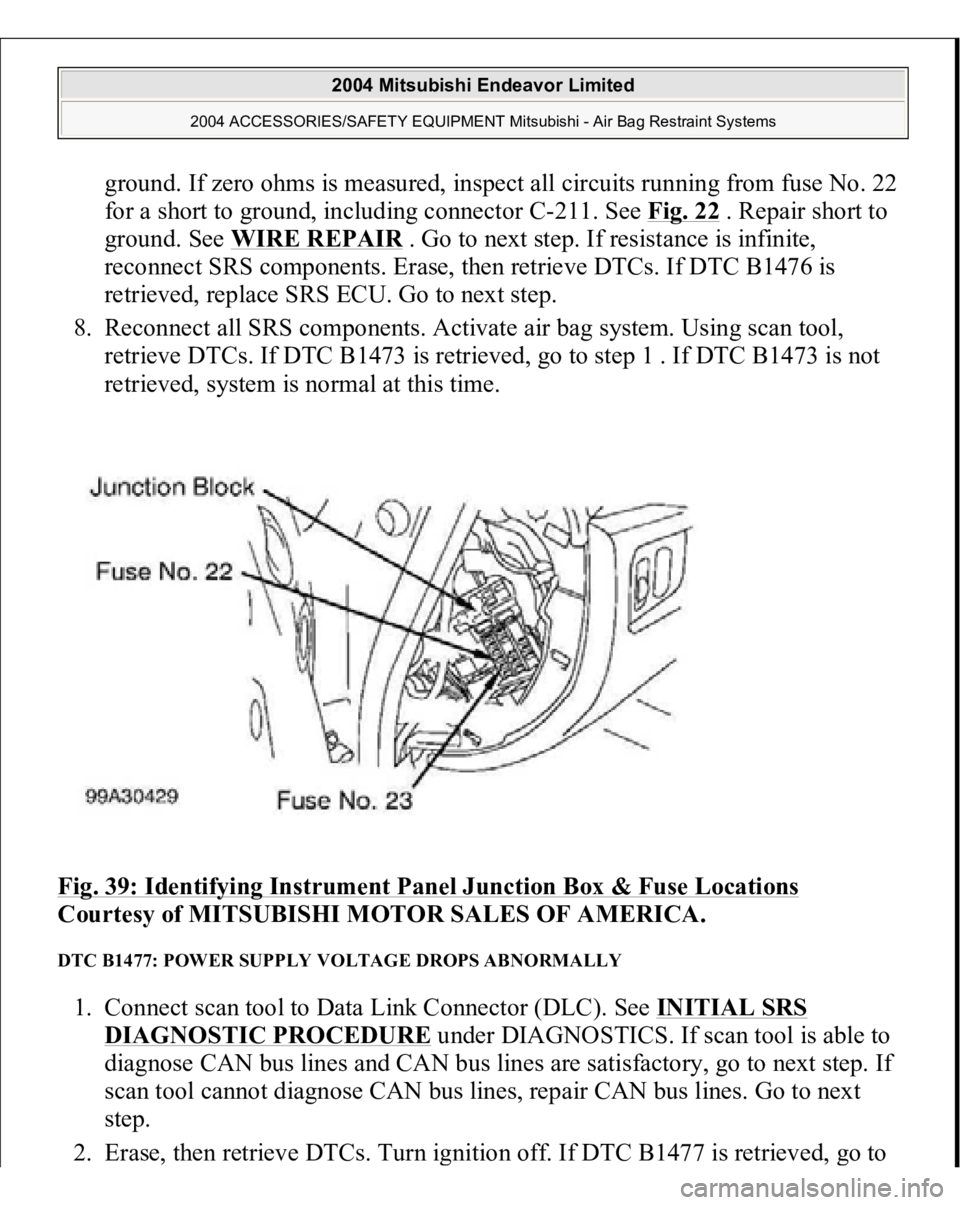
3. Remove fuse No. 22 from instrument panel junction block. See Fig. 39
. If fuse
is blown, go to step 6 . If fuse is not blown, go to next step.
4. Disconnect negative battery cable. Disconnect SRS ECU connector C-26. See
SRS ELECTRONIC CONTROL UNIT (SRS ECU)
under REMOVAL &
INSTALLATION. See Fig. 30
. Connect negative battery cable. Turn ignition
on. Measure voltage between ground and SRS ECU connector C-26, terminal
No. 23 (Black/White wire). If voltage is 9 volts or more, reconnect SRS
components. Erase, then retrieve DTCs. If DTC B1476 is retrieved, replace
SRS ECU. Go to step 8 . If DTC B1476 is not retrieved, go to next step.
5. Inspect Black/White wire between SRS ECU connector C-26, terminal No. 23
and ignition switch connector C-308, terminal No. 2. If wire is okay, go to step
8 . If wire is not okay, replace harness between SRS ECU and ignition switch.
Go to step 8 .
6. Replace fuse. Turn ignition on for one minute, then turn off. Inspect fuse. If
fuse is okay, go to step 8 . If fuse is not okay, go to next step.
7. Measure resistance between SRS ECU connector C-26
, terminal No. 23 and
2004 Mitsubishi Endeavor Limited
2004 ACCESSORIES/SAFETY EQUIPMENT Mitsubishi - Air Bag Restraint Systems
Page 395 of 3870
ground. If zero ohms is measured, inspect all circuits running from fuse No. 22
for a short to ground, including connector C-211. See Fig. 22
. Repair short to
ground. See WIRE REPAIR
. Go to next step. If resistance is infinite,
reconnect SRS components. Erase, then retrieve DTCs. If DTC B1476 is
retrieved, replace SRS ECU. Go to next step.
8. Reconnect all SRS components. Activate air bag system. Using scan tool,
retrieve DTCs. If DTC B1473 is retrieved, go to step 1 . If DTC B1473 is not
retrieved, system is normal at this time.
Fig. 39: Identifying Instrument Panel Junction Box & Fuse Locations
Courtesy of MITSUBISHI MOTOR SALES OF AMERICA.
DTC B1477: POWER SUPPLY VOLTAGE DROPS ABNORMALLY 1. Connect scan tool to Data Link Connector (DLC). See INITIAL SRS
DIAGNOSTIC PROCEDURE
under DIAGNOSTICS. If scan tool is able to
diagnose CAN bus lines and CAN bus lines are satisfactory, go to next step. If
scan tool cannot diagnose CAN bus lines, repair CAN bus lines. Go to next
step.
2. Erase, then retrieve DTCs. Turn ignition off. If DTC B1477 is retrieved,
go to
2004 Mitsubishi Endeavor Limited
2004 ACCESSORIES/SAFETY EQUIPMENT Mitsubishi - Air Bag Restraint Systems