steering MITSUBISHI ENDEAVOR 2004 Service Repair Manual
[x] Cancel search | Manufacturer: MITSUBISHI, Model Year: 2004, Model line: ENDEAVOR, Model: MITSUBISHI ENDEAVOR 2004Pages: 3870, PDF Size: 98.47 MB
Page 209 of 3870
Courtesy of MITSUBISHI MOTOR SALES OF AMERICA
.
6. Turn the ignition switch to the "LOCK" (OFF) position.
Q: Is DTC U1073 set?
YES: Go to Step 1 .
NO: The procedure is complete.
SYMPTOM CHART NOTE: For vehicle with TCL/ASC, refer to SYMTOM CHART
.
CAUTION: During diagnosis, a DTC code associated with other
system may be set when the ignition switch is turned
on with connector(s) disconnected. On completion,
confirm all systems for DTC code(s). If DTC code(s)
are set, erase them all.
NOTE: If steering movements are made when driving at high
speed, or when driving on road surfaces with low frictional
resistance, or when passing over bumps, the ABS may
operate although sudden braking is not being applied.
Because of this, when getting information from the
customer, check if the problem occurred while driving
under such conditions as these.
NOTE: During ABS operation, the brake pedal may vibrate a little
or may not be able to be pressed. Such conditions are due
to intermittent changes in hydraulic pressure inside the
brake line to prevent the wheels from locking. This is
normal.
2004 Mitsubishi Endeavor LS
2004 BRAKES Anti-Lock Braking System (ABS) - Endeavor
Page 278 of 3870
On-vehicle Deployment 1. Before proceeding, see
AIR BAG SAFETY PRECAUTIONS
. Move vehicle
to an isolated area. Open all doors and windows. Disconnect and shield
negative battery cable end. Disconnect positive battery cable. Remove battery
from vehicle. Wait at least 60 seconds before continuing.
2. To deploy driver-side air bag module, remove steering column lower cover.
Disconnect lower clockspring Yellow 4-pin connector. Cut harness side of
connector from wire harness and strip ends of driver-side air bag module wires
on harness side of clockspring connector. See
WIRING DIAGRAMS
.
3. To deploy passenger-side air bag module, remove glove box and glove box
outer case. Disconnect passenger-side air bag module Red connector.
4. To deploy side impact air bag module, disconnect appropriate side impact air
bag module Red connector, located under front seat.
5. To deploy seat belt pretensioner, disconnect appropriate seat belt pretensioner
connector, located at seat belt pretensioner.
6. Fabricate a de
ployment harness usin
g two wires at least 20 feet
(6.1 m
) in
WARNING:Air bag modules and seat belt pretensioners make
loud noises during deployment. Air bag module and
seat belt pretensioner deployment could cause
personal injury. Always deploy components
outdoors and away from people. Never deploy air
bag modules with trim cover face down.
NOTE: If vehicle is to be scrapped, perform On-vehicle
deployment. See ON
-VEHICLE DEPLOYMENT
. If vehicle
will continue to be operated, perform Off-vehicle
Deployment. See OFF
-VEHICLE DEPLOYMENT
.
NOTE: Driver-side and passenger-side air bag modules will be
either single-stage or dual-stage. Consult wiring
diagrams to ensure correct wires are cut and spliced
prior to deployment. See WIRING DIAGRAMS
.
2004 Mitsubishi Endeavor Limited
2004 ACCESSORIES/SAFETY EQUIPMENT Mitsubishi - Air Bag Restraint Systems
Page 281 of 3870
When a vehicle has been involved in a collision, certain components of the passive
restraint system must be inspected or replaced. See
AIR BAG/SRS
COMPONENT INSPECTION & REPLACEMENT TABLES
article in the
GENERAL INFORMATION section.
REMOVAL & INSTALLATION DRIVER-SIDE AIR BAG MODULE & CLOCKSPRING Removal & Installation (With Single-stage AIR Bag System) 1. Before proceeding, see
AIR BAG SAFETY PRECAUTIONS
. Ensure front
wheels are in straight-ahead position. Turn ignition off. Disable air bag system.
See
DISABLING & ACTIVATING AIR BAG SYSTEM
.
2. Remove lower cover from steering wheel. Remove driver-side air bag module
bolts from rear of steering wheel. Remove driver-side air bag module. See
Fig.
3 . Remove damper weight from steering wheel. Remove steering wheel nut
and discard. Using Steering Wheel Puller (MB990803), remove steering wheel.
3. Remove upper and lower steering column covers. Disconnect clockspring
electrical connectors. Remove clockspring screws. Remove clockspring from
steering column.
4. To install, reverse removal procedure. If necessary, center clockspring. See CENTERING CLOCKSPRING
under ADJUSTMENTS. Tighten
clockspring screws, NEW steering wheel nut and driver-side air bag module
bolts to specification. See
TORQUE SPECIFICATIONS
. Activate air bag
s
ystem. WARNING:Accidental air bag deployment is possible. Personal
injury may result. Read and follow all WARNINGS
and AIR BAG SAFETY PRECAUTIONS
before
working on air bag system or related components.
2004 Mitsubishi Endeavor Limited
2004 ACCESSORIES/SAFETY EQUIPMENT Mitsubishi - Air Bag Restraint Systems
Page 282 of 3870
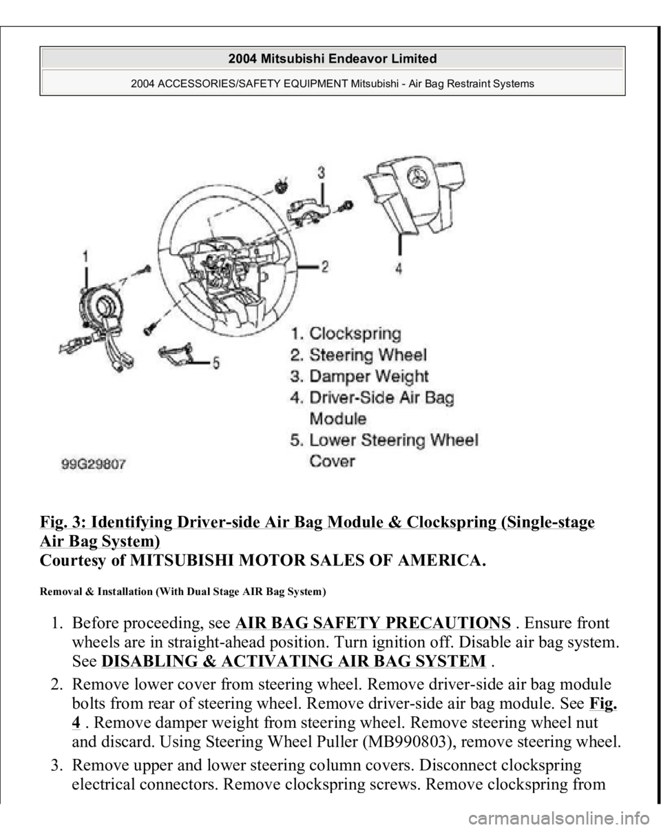
Fig. 3: Identifying Driver
-side Air Bag Module & Clockspring (Single
-stage
Air Bag System)
Courtesy of MITSUBISHI MOTOR SALES OF AMERICA.
Removal & Installation (With Dual Stage AIR Bag System) 1. Before proceeding, see
AIR BAG SAFETY PRECAUTIONS
. Ensure front
wheels are in straight-ahead position. Turn ignition off. Disable air bag system.
See
DISABLING & ACTIVATING AIR BAG SYSTEM
.
2. Remove lower cover from steering wheel. Remove driver-side air bag module
bolts from rear of steering wheel. Remove driver-side air bag module. See Fig.
4 . Remove damper weight from steering wheel. Remove steering wheel nut
and discard. Using Steering Wheel Puller (MB990803), remove steering wheel.
3. Remove upper and lower steering column covers. Disconnect clockspring
electrical connectors. Remove clocks
prin
g screws. Remove clocks
prin
g from
2004 Mitsubishi Endeavor Limited
2004 ACCESSORIES/SAFETY EQUIPMENT Mitsubishi - Air Bag Restraint Systems
Page 283 of 3870
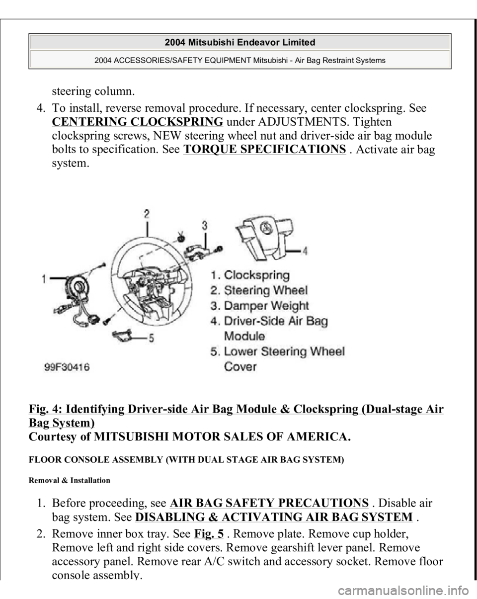
steering column.
4. To install, reverse removal procedure. If necessary, center clockspring. See
CENTERING CLOCKSPRING
under ADJUSTMENTS. Tighten
clockspring screws, NEW steering wheel nut and driver-side air bag module
bolts to specification. See TORQUE SPECIFICATIONS
. Activate air bag
system.
Fig. 4: Identifying Driver
-side Air Bag Module & Clockspring (Dual
-stage Air
Bag System)
Courtesy of MITSUBISHI MOTOR SALES OF AMERICA.
FLOOR CONSOLE ASSEMBLY (WITH DUAL STAGE AIR BAG SYSTEM) Removal & Installation 1. Before proceeding, see AIR BAG SAFETY PRECAUTIONS
. Disable air
bag system. See DISABLING & ACTIVATING AIR BAG SYSTEM
.
2. Remove inner box tray. See Fig. 5
. Remove plate. Remove cup holder,
Remove left and right side covers. Remove gearshift lever panel. Remove
accessory panel. Remove rear A/C switch and accessory socket. Remove floor
console assembl
y.
2004 Mitsubishi Endeavor Limited
2004 ACCESSORIES/SAFETY EQUIPMENT Mitsubishi - Air Bag Restraint Systems
Page 286 of 3870
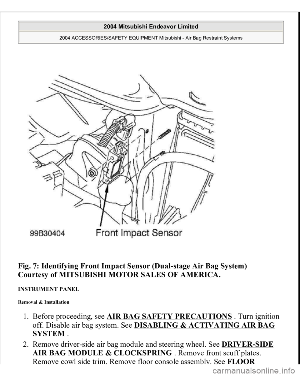
Fig. 7: Identifying Front Impact Sensor (Dual
-stage Air Bag System)
Courtesy of MITSUBISHI MOTOR SALES OF AMERICA.
INSTRUMENT PANEL Removal & Installation 1. Before proceeding, see AIR BAG SAFETY PRECAUTIONS
. Turn ignition
off. Disable air bag system. See DISABLING & ACTIVATING AIR BAG
SYSTEM
.
2. Remove driver-side air bag module and steering wheel. See DRIVER
-SIDE
AIR BAG MODULE & CLOCKSPRING
. Remove front scuff plates.
Remove cowl side trim. Remove floor console assembl
y. See FLOOR
2004 Mitsubishi Endeavor Limited
2004 ACCESSORIES/SAFETY EQUIPMENT Mitsubishi - Air Bag Restraint Systems
Page 287 of 3870
CONSOLE ASSEMBL
Y . Remove left and right A-pillar trim panels.
Remove hood lock release handle.
3. Remove end panel. See Fig. 8
. Remove driver-side knee bolster. Remove fog
light switch. Remove steering column upper and lower covers. Remove
combination meter assembly. Remove center panel assembly. Remove air
vents. Remove radio panel. Remove AC-heater control assembly.
4. Remove hazard warning switch. Remove console meter hood. Remove multi-
center display unit. Remove audio components. Remove glove box assembly.
Remove left and right speaker covers. Remove speakers. Disconnect
clockspring and steering column switch connectors. Remove photo sensor and
photo sensor clamp.
5. Remove interior temperature sensor. Disconnect passenger-side air bag module
connector. Remove left and right center instrument panel brackets. Disconnect
remaining electrical connectors. Remove instrument panel nuts and bolts.
Remove instrument panel.
6. To install, reverse removal procedure. Tighten NEW steering wheel nut and
drive
r-side air ba
g module bolts to s
pecification. Activate air ba
g system.
2004 Mitsubishi Endeavor Limited
2004 ACCESSORIES/SAFETY EQUIPMENT Mitsubishi - Air Bag Restraint Systems
Page 299 of 3870
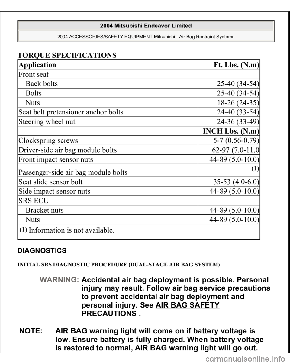
TORQUE SPECIFICATIONS DIAGNOSTICS INITIAL SRS DIAGNOSTIC PROCEDURE (DUAL-STAGE AIR BAG SYSTEM) Application
Ft. Lbs. (N.m)
Front seatBack bolts
25-40 (34-54)
Bolts
25-40 (34-54)
Nuts
18-26 (24-35)
Seat belt pretensioner anchor bolts
24-40 (33-54)
Steering wheel nut
24-36 (33-49)
INCH Lbs. (N.m)
Clockspring screws
5-7 (0.56-0.79)
Driver-side air bag module bolts
62-97 (7.0-11.0
Front impact sensor nuts
44-89 (5.0-10.0)
Passenger-side air bag module bolts
(1)
Seat slide sensor bolt
35-53 (4.0-6.0)
Side impact sensor nuts
44-89 (5.0-10.0)
SRS ECUBracket nuts
44-89 (5.0-10.0)
Nuts
44-89 (5.0-10.0)
(1)
Information is not available.
WARNING:Accidental air bag deployment is possible. Personal
in
jury ma
y result. Follow air ba
g service precautions
to prevent accidental air bag deployment and
personal injury. See AIR BAG SAFETY
PRECAUTIONS
.
NOTE: AIR BAG warning light will come on if battery voltage is
low. Ensure battery is fully charged. When battery voltage
is restored to normal, AIR BAG warning light will go out.
2004 Mitsubishi Endeavor Limited
2004 ACCESSORIES/SAFETY EQUIPMENT Mitsubishi - Air Bag Restraint Systems
Page 701 of 3870
2004 BRAKES
Basic Brake System - Endeavor
GENERAL DESCRIPTION The brake system has been designed to give greater reliability and durability and to
provide excellent braking performance. FEATURES IMPROVED BRAKING PERFORMANCE 1. A 9+10 inch tandem brake booster has been adopted to provide sufficient
braking force in sudden braking range.
2. Front ventilated disc brakes have been adopted to provide stabled braking force
and improved braking feel.
3. Rear solid disc brakes have been adopted. IMPROVED STABILITY 1. A 4-wheel anti-lock braking system (4ABS) has been adopted to prevent
slipping caused by the vehicle wheels locking up, in order to maintain a stable
vehicle posture and steering performance.
2. An electronic brake-force distribution (EBD) makes it possible to maintain the
maximum amount of braking force even when the vehicle's load is unevenly
distributed. < Vehicles with ABS>
3. A rear wheel early lock-prevention proportioning valve has been adopted. <
Vehicles without ABS>
4. Front- and rear-wheel X-type brake line layout has been adopted.
5. Ventilated discs have been adopted for front brakes in order to improve anti-
fading performance. IMPROVED SERVICEABILITY 1. A diagnosis function has been adopted for the ABS system in order to make
inspection easier.
2. An outer disc separated hub and rotor has been adopted to make removal and
2004 Mitsubishi Endeavor LS
2004 BRAKES Basic Brake System - Endeavor
2004 Mitsubishi Endeavor LS
2004 BRAKES Basic Brake System - Endeavor
Page 1071 of 3870
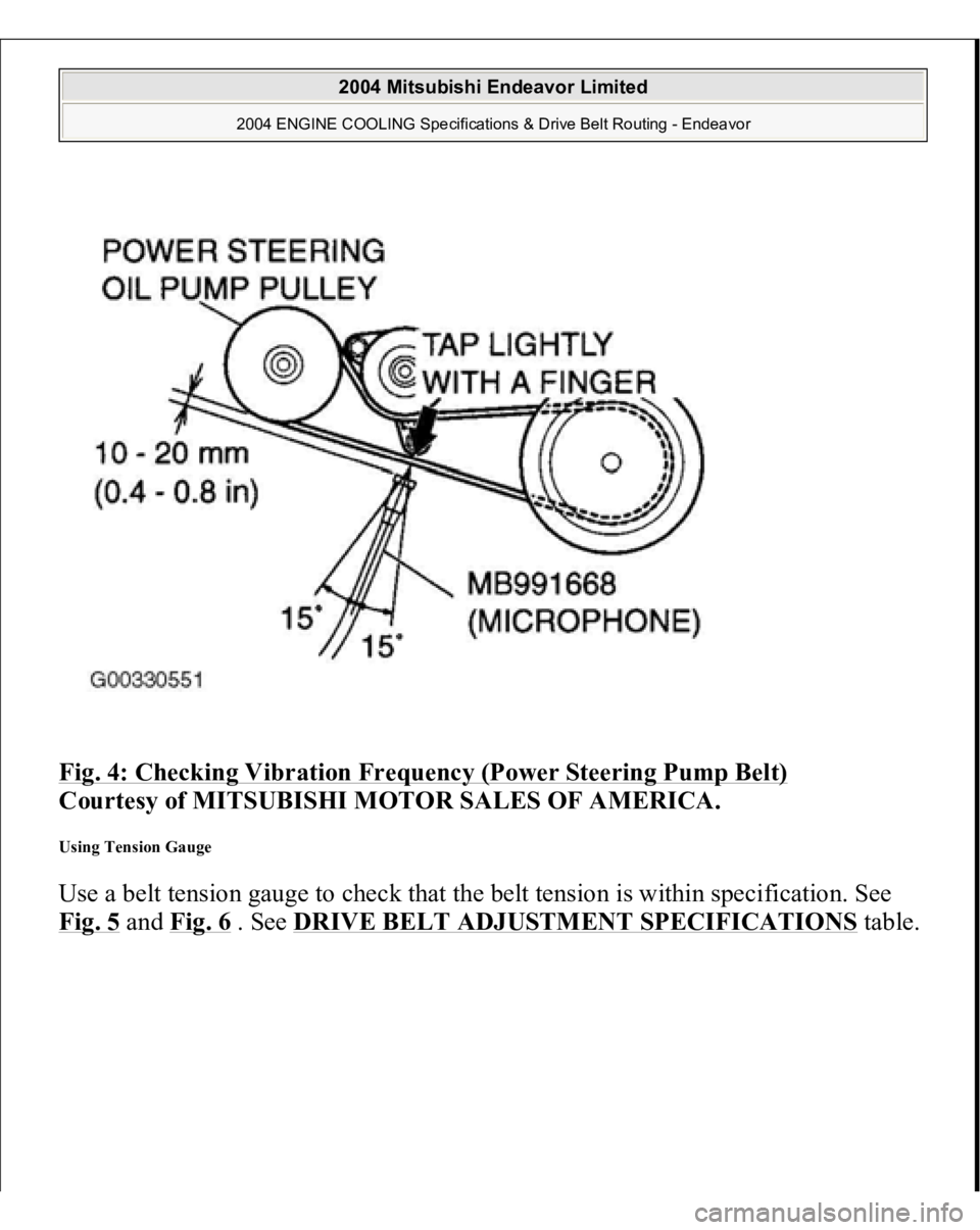
Fig. 4: Checking Vibration Frequency (Power Steering Pump Belt)
Courtesy of MITSUBISHI MOTOR SALES OF AMERICA.
Using Tension Gauge Use a belt tension gauge to check that the belt tension is within specification. See
Fig. 5
an
d Fig. 6
. See DRIVE BELT ADJUSTMENT SPECIFICATIONS
table.
2004 Mitsubishi Endeavor Limited
2004 ENGINE COOLING Specifications & Drive Belt Routing - Endeavor