battery MITSUBISHI GALANT 1989 Service Owner's Manual
[x] Cancel search | Manufacturer: MITSUBISHI, Model Year: 1989, Model line: GALANT, Model: MITSUBISHI GALANT 1989Pages: 1273, PDF Size: 37.62 MB
Page 224 of 1273
13-82 FUEL SYSTEM
OPERATION
l The power-steering pressure switch functions
to convert data as to whether there is or is not apower steering load to LOW-or HIGH-level vol-
tage, and the resulting signals are input to the engine control module. The engine control mod-
ule, based upon those signals, regulates the
idle-speed control motor. l The battery voltage within the engine control
module is applied, by way of the resistance, to
the power-steering pressure switch. When
steering maneuvers are made, the pressure of
the power-steering oil increases, thus switching
ON the power-steering pressure switch, with
the result that the current is grounded. As a re-
sult, the power-steering pressure switch vol-
tage changes from HIGH level to LOW level.
INSPECTION I) Using Scan tool
Function
Item No.
Data reading 27
Data displayInspection conditions Steering wheelNormal indication
Switch status Engine: IdlingSteering wheel idle stateOFF
During steering wheelONoperation
(2) Checking Oil Pressure
Steering wheel
Straight forward
Turned
Oil pump delivery pressure (ref. value)
less than 1,470- 1,961 kPa (213-284 psi)
more than
1,470- 1,961 kPa (213-284 psi)
HARNESS INSPECTION
I-E-I
Harness side connector 6 0
@=- -0
Q
4 1
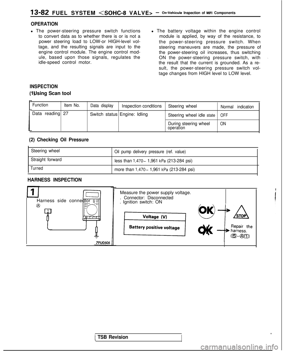
Measure the power supply voltage.
. Connector: Disconnected. Ignition switch: ON
[ TSB Revision
Page 225 of 1273
FUEL SYSTEM
inspection of MFI Components13-83
AIR CONDITIONING SWITCH AND A/C COMPRESSOR CLUTCH RELAYM13YRAE
Air conditioning switch
Sub fl
FUSC?
Air conditic@compresscclutch relal
Magnetic
clutch
Jsibie li
7
)ningIr /k
!Ik 171 control unitAuto compressor
-
-
)N
Engine control 65moduleA I7
‘1
6FU1411
Engine control module connector
IhJ-Jl r--vrJ=-Jl/l
OlLO838
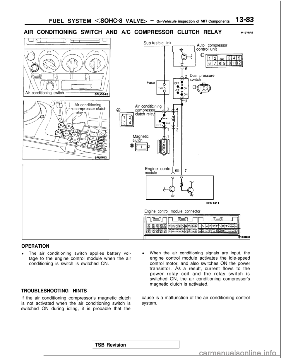
OPERATION
l
The air conditioning switch applies battery vol-
tage to the engine control module when the air
conditioning is switch is switched ON.
TROUBLESHOOTING HINTS
If the air conditioning compressor’s magnetic clutch
is not activated when the air conditioning switch is
switched ON during idling, it is probable that the l
When the air conditioning signals are input, the
engine control module activates the idle-speed
control motor, and also switches ON the power
transistor.
AS a result, current flows to the
power relay coil and the relay switch is
switched ON, the air conditioning compressor’s
magnetic clutch is activated.
cause is a malfunction of the air conditioning control
system.
TSB Revision
Page 232 of 1273
13-90 FUEL SYSTEM
INJECTORS
Fuel
Connector
Solenoid coil
Plunger
Needle valve -----I
InjectionFilter6FUO514
M13rrAA
Multiport
fuel injection relay
No.1 &j No.2& No.3& No,4+
tI
lFUO642
Engine control module connector
CJ=JW=U-I
0 1 LO636
OPERATION
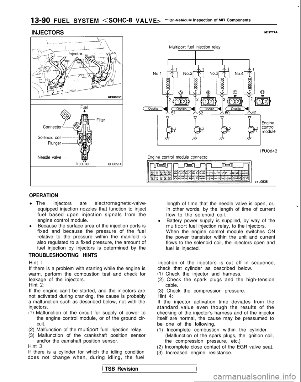
l The
injectorsare electromagnetic-valve-
equipped injection nozzles that function to inject
fuel based upon injection signals from the
engine control module.
lBecause the surface area of the injection ports is
fixed and because the pressure of the fuel
relative to the pressure within the manifold is
also regulated to a fixed pressure, the amount of
fuel injection by injectors is determined by the
TROUBLESHOOTING HINTS
Hint 1:
If there is a problem with starting while the engine is
warm, perform the combustion test and check for leakage of the injectors.
Hint
2,
If the engine can’t be started, and the injectors are
not activated during cranking, the cause is probably
a malfunction such as described below, not with the
injectors.
(I) Malfunction of the circuit for supply of power to the engine control module, or of the ground cir-
cuit.
(2) Malfunction of the multiport fuel injection relay.
(3) Malfunction of the crankshaft position sensor and/or the camshaft position sensor.
Hint
3.
If there is a cylinder for which the idling condition
does not change when, during idling, the fuel length of time that the needle valve is open, or,
in other words, by the length of time of current
~-
flow to the solenoid coil.
lBattery power supply is supplied, by way of the
multiport fuel injection relay, to the injectors.
When the engine control module switches ON
the power transistor within the unit and current
flows to the solenoid coil, the injectors open and
fuel is injected.
injection of the injectors is cut off in sequence,
check that cylinder as described below.
(1) Check the injector and harness.
(2) Check the spark plugs and the high-tension
cable.
(3) Check the compression pressure. Hint 4:
If the injector activation time deviates from the
standard value even though the results of the
checking of the injector’s harness and of the injector itself are normal, the cause may be pressumed to
be one of the following,
(1) Incomplete combustion within the cylinder. (Malfunction of the spark plugs, the ignition coil,
the compression pressure, etc.)
(2) Incomplete close contact of the EGR valve seat.
(3) Increased engine resistance.
1 TSB RevisionI
Page 238 of 1273
13-96 FUEL SYSTEM
IGNITION COIL AND IGNITION POWER TRANSISTOR
ignition coil (IGI)
Ml3WAA
Harness side
@connector0
Harness side
Component side
Distributor\/ 2
4.I_lgnltion. .!
I@LZ)
TachcImetertimingA? I--:*:^^adjustment-_
Lllrnacr
r;rlnI 101 i IG.72 Jl”F
Componenr side
6FU1280
OPERATION
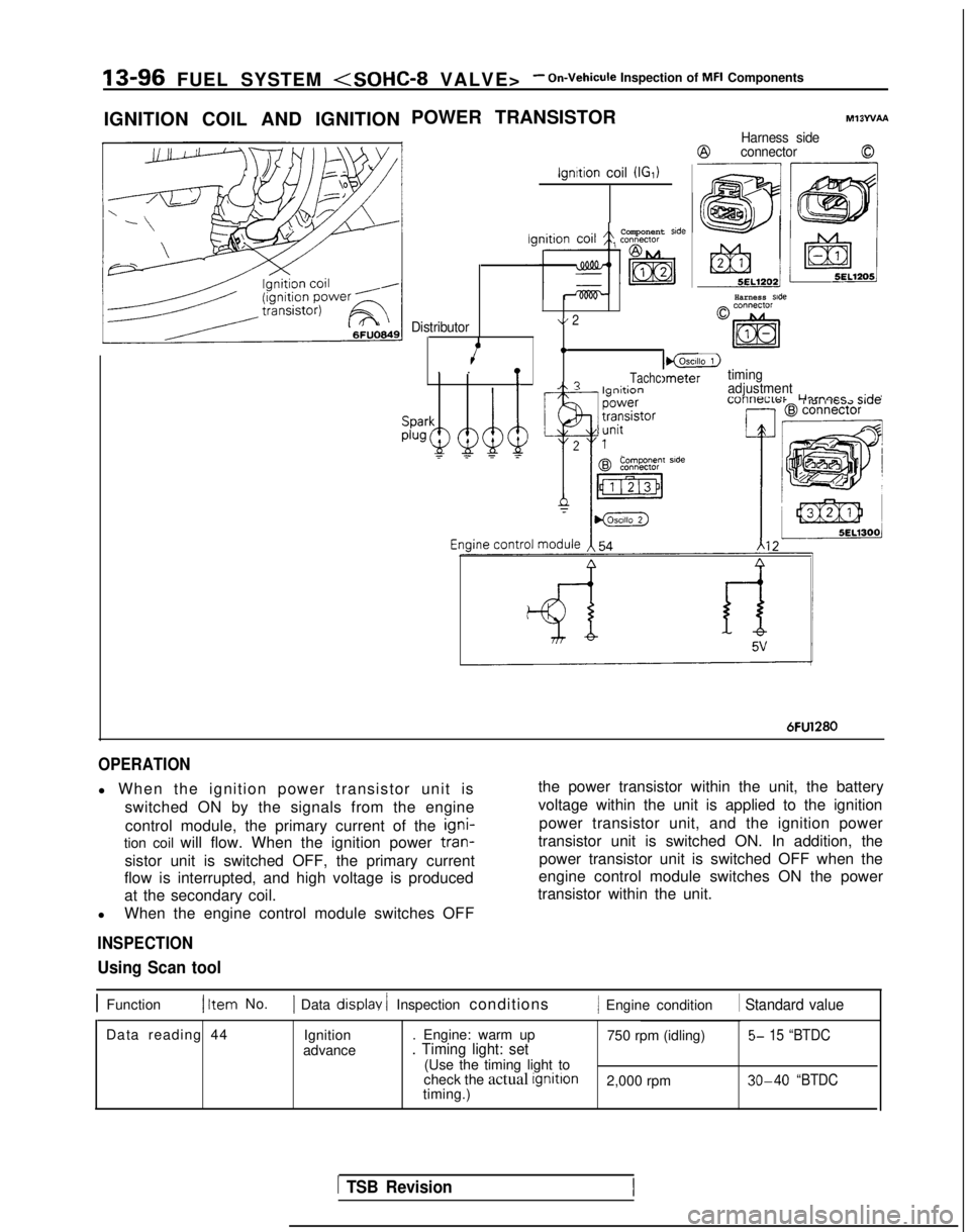
l When the ignition power transistor unit is
switched ON by the signals from the engine
control module, the primary current of the igni-
tion coil will flow. When the ignition power tran-
sistor unit is switched OFF, the primary current
flow is interrupted, and high voltage is produced
at the secondary coil.
l When the engine control module switches OFF
INSPECTION
the power transistor within the unit, the battery
voltage within the unit is applied to the ignition
power transistor unit, and the ignition power
transistor unit is switched ON. In addition, the power transistor unit is switched OFF when the
engine control module switches ON the power
transistor within the unit.
Using Scan tool
1 Function1 Item No.1 Data display / Inspection conditions/ Engine condition 1 Standard value
Data reading 44
Ignition
advance . Engine: warm up
750 rpm (idling)5- 15 “BTDC. Timing light: set(Use the timing light to
check the actual ignition
2,000 rpm 30-40 “BTDCtiming.)
1 TSB Revision
Page 241 of 1273
FUEL SYSTEM
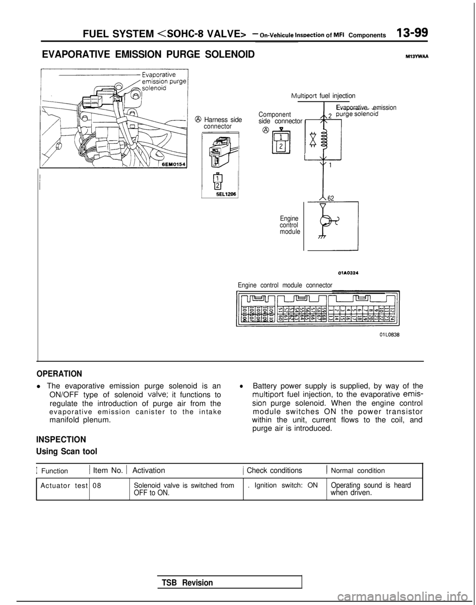
EVAPORATIVE EMISSION PURGE SOLENOIDMlBYwAA
Multiport fuel injection
@ Harness sideconnector Componentside connector
i
5EL1206
Engine
control
module
TSB Revision
Evaporative emission
62
Engine control module connectorI,
OlLO838
OPERATION
l The evaporative emission purge solenoid is an
ON/OFF type of solenoid valve;
it functions to
regulate the introduction of purge air from the
evaporative emission canister to the intake
manifold plenum.
INSPECTION
Using Scan tool
lBattery power supply is supplied, by way of the multiport
fuel injection, to the evaporative emis-
sion purge solenoid. When the engine control
module switches ON the power transistor
within the unit, current flows to the coil, and
purge air is introduced.
IFunction1 Item No. 1 Activation1 Check conditions1 Normal condition
Actuator test 08 Solenoid valve is switched from . Ignition switch: ON
Operating sound is heard
OFF to ON.when driven.
Page 242 of 1273
13-100 FUEL SYSTEM
- On-Vehicule Inspection of MFI Components
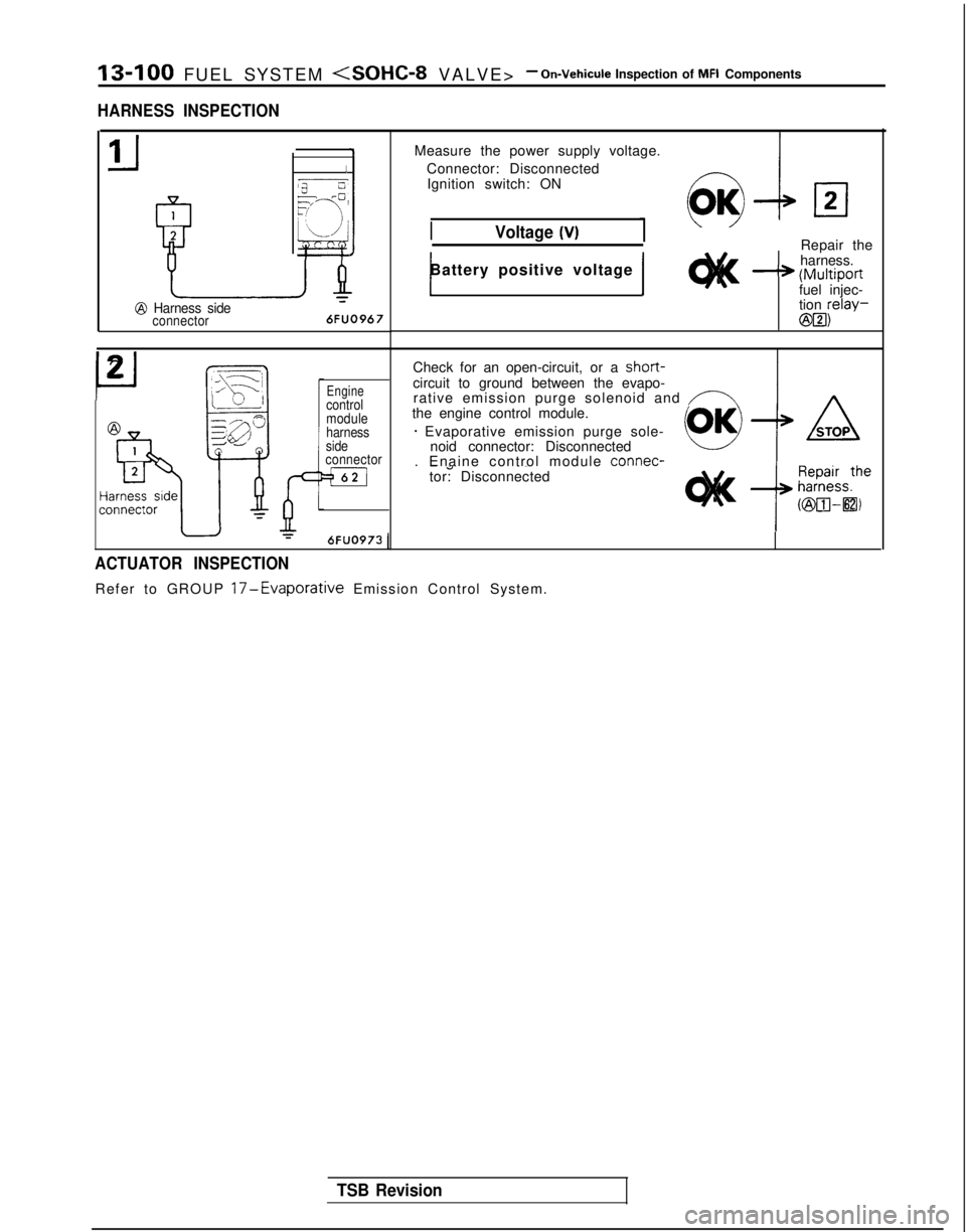
HARNESS INSPECTION
1
2
P
Izj----=2T !r/
‘3“L j
k&
-&@ Harness sideconnector
6FUO967
Measure
the power supply voltage.
Connector: Disconnected Ignition switch: ON
Voltage (V)Repair the
harness.
-* (Multiportfuel injec-
tion relay-
@B3)
1Battery positive voltage 1
P
2_Fq,/-\i-1- /-
F
&--
Y
Enginecontrol
module
harness
side
connector
=m
Check for an open-circuit, or a short-circuit to ground between the evapo-
rative emission purge solenoid and /-Athe engine control module.
* Evaporative emission purge sole- noid connector: Disconnected
. Enaine control module connec-
-a ~~tor: Disconnected
6FUO973
1
ACTUATOR INSPECTION
Refer to GROUP 17-Evaporative Emission Control System.
TSB Revision
Page 243 of 1273
FUEL SYSTEM
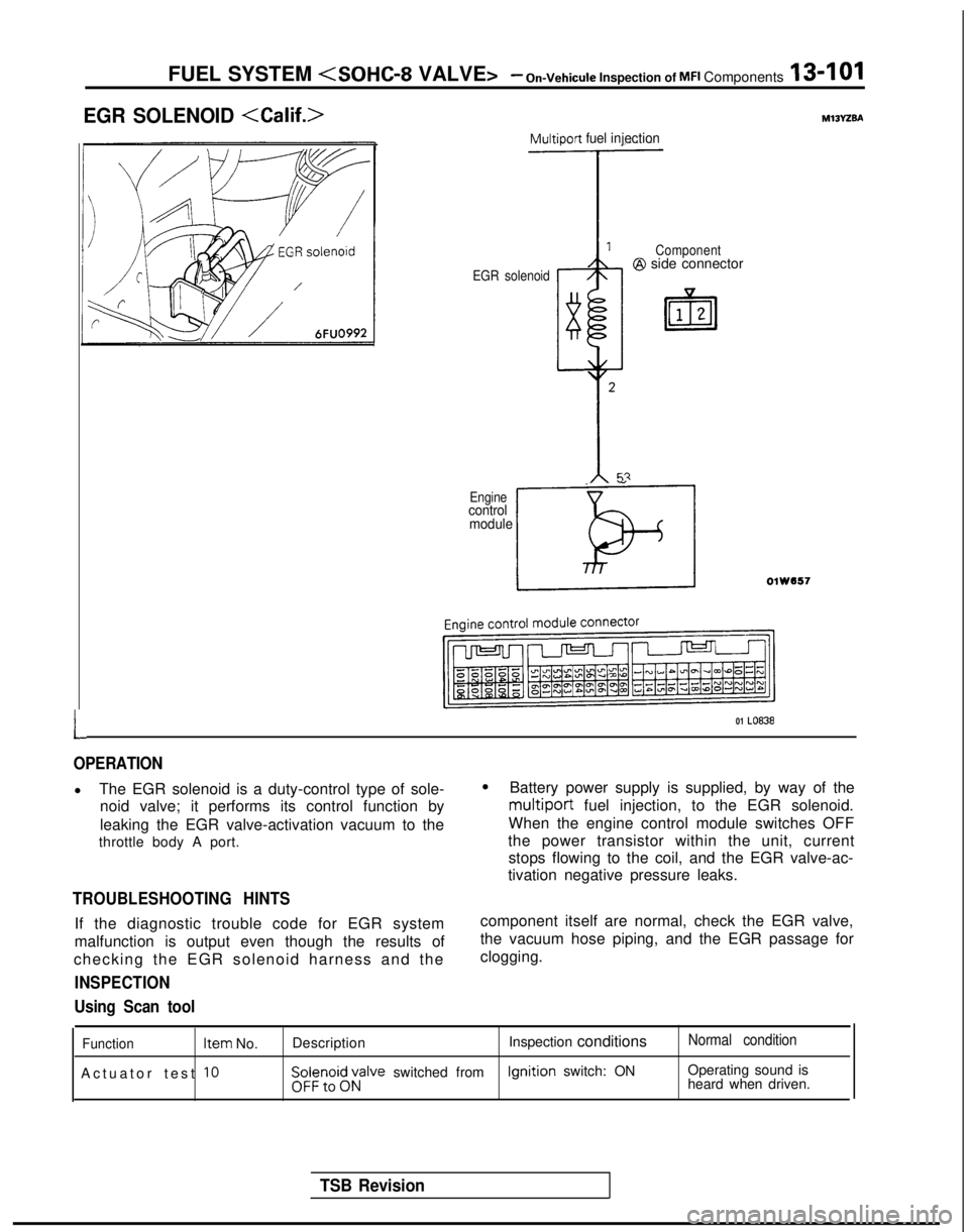
EGR SOLENOID
L
Multiport fuel injection
EGR solenoid Component@I side connector
_ ”
Enginecontrol
module
LOlW557
01 LO838
OPERATION
l The EGR solenoid is a duty-control type of sole-
noid valve; it performs its control function by
leaking the EGR valve-activation vacuum to the
throttle body A port.
TROUBLESHOOTING HINTS
If the diagnostic trouble code for EGR system
malfunction is output even though the results of
checking the EGR solenoid harness and the
INSPECTION
l Battery power supply is supplied, by way of the
multiport fuel injection, to the EGR solenoid.
When the engine control module switches OFF
the power transistor within the unit, current stops flowing to the coil, and the EGR valve-ac-
tivation negative pressure leaks.
component itself are normal, check the EGR valve,
the vacuum hose piping, and the EGR passage for
clogging.
Using Scan tool
Function Item
No.
Actuator test
10
Description Inspection conditionsNormal condition
$i;;,oi$;;alve switched from Ignition
switch: ON Operating sound is
heard when driven.
TSB Revision
Page 244 of 1273
13-102 FUEL SYSTEM
- On-Vehicule Inspection of MFI Components
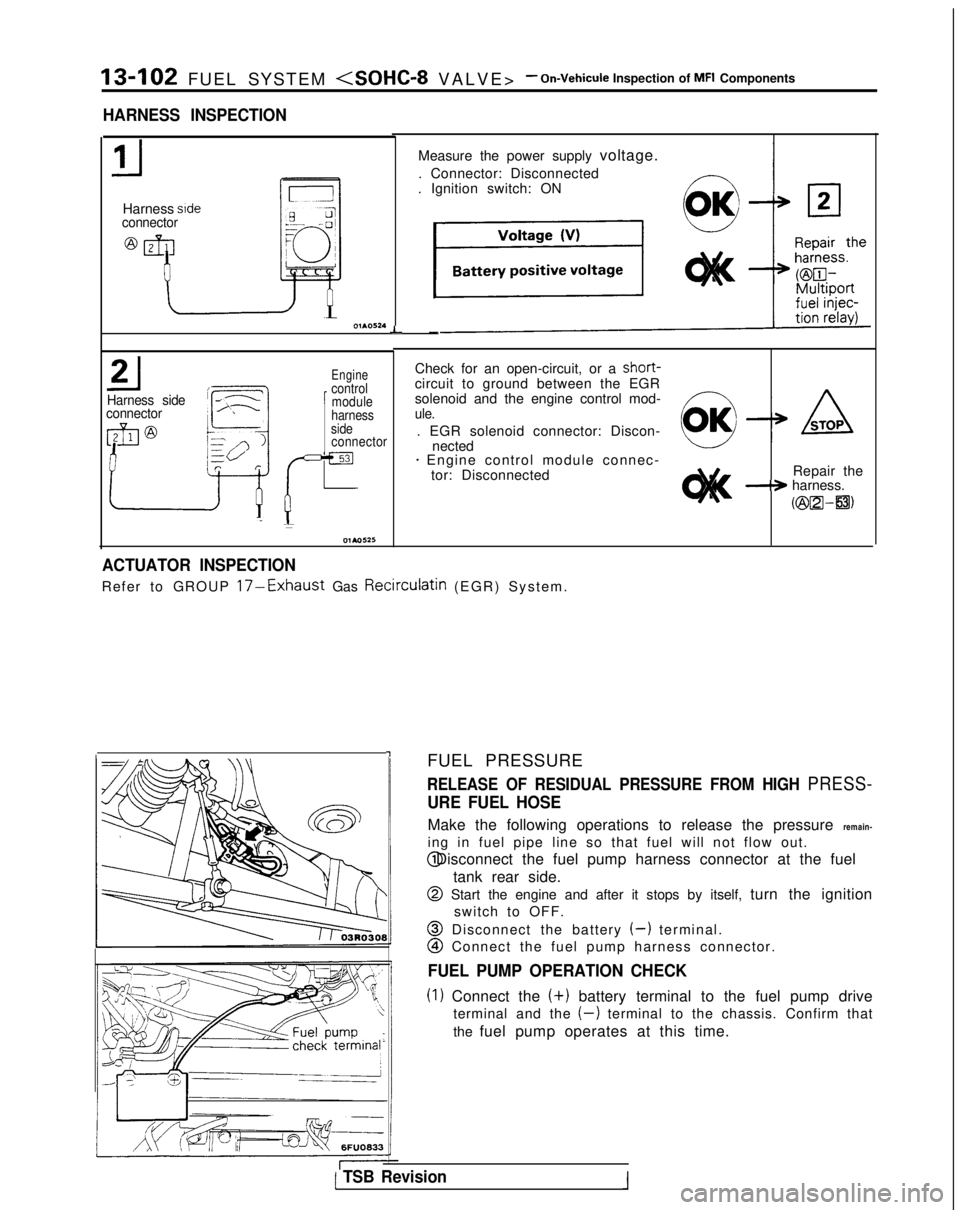
HARNESS INSPECTION
Harness sideconnector
L
Harness side
connector
Engine
1
control module
Check for an open-circuit, or a short-
circuit to ground between the EGR
solenoid and the engine control mod-
harnessule.side. EGR solenoid connector: Discon-connectornected+ Engine control module connec- tor: Disconnected Repair the
-+ harness.
Kzix2l-a)
-I
Measure the power supply voltage.
. Connector: Disconnected
. Ignition switch: ON
-
ACTUATOR INSPECTION
Refer to GROUP 17-Exhaust Gas Recirculatin (EGR) System
.
FUEL PRESSURE
RELEASE OF RESIDUAL PRESSURE FROM HIGH PRESS-
URE FUEL HOSE
Make the following operations to release the pressure remain-
ing in fuel pipe line so that fuel will not flow out. @ Disconnect the fuel pump harness connector at the fuel
tank rear side.
@ Start the engine and after it stops by itself, turn the ignitionswitch to OFF.
@ Disconnect the battery (-) terminal.
@I Connect the fuel pump harness connector.
FUEL PUMP OPERATION CHECK
(1) Connect the (+)
battery terminal to the fuel pump drive
terminal and the
(-) terminal to the chassis. Confirm that
the fuel pump operates at this time.
( TSB Revision1
Page 245 of 1273
FUEL SYSTEM
TSB Revision
---
I g$qfq, tcJ-s6FUO633
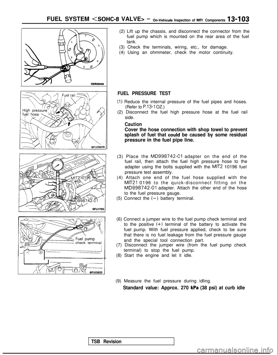
(2) Lift up the chassis, and disconnect the connector from the
fuel pump which is mounted on the rear area of the fuel
tank.
(3) Check the terminals, wiring, etc., for damage.
(4) Using an ohmmeter, check the motor continuity.
FUEL PRESSURE TEST
(1) Reduce the internal pressure of the fuel pipes and hoses.
(Refer to P.13-1 OZ.)
(2) Disconnect the fuel high pressure hose at the fuel rail
side.
Caution
Cover the hose connection with shop towel to prevent
splash of fuel that
could be caused by some residual
pressure in the fuel pipe line.
(3) Place the
MD998742-01 adapter on the end of the
fuel rail, then attach the fuel high pressure hose to the
adapter using the bolts supplied with the
MIT2 10196 fuel
pressure test assembly.
(4) Attach one end of the fuel hose supplied with the
MIT21 0196 to the quick-disconnect fitting on the
MD998742-01 adapter. Attach the other end of the hose
to the fuel pressure gauge.
(5) Connect the
(-) battery terminal.
(6) Connect a jumper wire to the fuel pump check terminal and to the positive
(+) terminal of the battery to activate the
fuel pump. With fuel pressure applied, check to be sure
that there is no fuel leakage from the fuel pressure gauge
and the special tool connection part.
(7) Disconnect the jumper wire (from the fuel pump check
terminal) to stop the fuel pump.
(8) Start the engine and let it idle.
(9) Measure the fuel pressure during idling.
Standard value: Approx. 270 kPa (38 psi) at curb idle
Page 247 of 1273
FUEL SYSTEM
fine probe7FU1264 1
(15) Reduce the internal pressure of the fuel pipes and hoses.
(Refer to
P.13-102.)
(16) Disconnect the fuel pressure gauge and the special toolsfrom the fuel rail.
Caution
Because there will be some residual pressure in the fuel
pipe line, use a shop towel to cover so that fuel doesn’t
splatter.
(17)Replace the O-ring at the end of the fuel high-pressure
hose with a new one. (18)After
connecting the fuel high-pressure hose to the fuel
rail, tighten the installation bolt.
(19)Check to be sure that there is no fuel leakage.
@ Apply battery voltage to the terminal for activation of the fuel pump so as to activate the fuel pump.
@ With fuel pressure applied, check for leakage of the fuel
line.
INSPECTION OF ENGINE CONTROL MODULE
TERMINAL VOLTAGEMl 3ZALBa
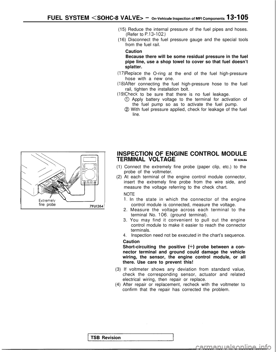
(1) Connect the extremely fine probe (paper clip, etc.) to the probe of the voltmeter.
(2) At each terminal of the engine control module connector,
insert the extremely fine probe from the wire side, and
measure the voltage referring to the check chart.
NOTE
1. In the state in which the connector of the engine
control module is connected, measure the voltage.
2. Measure the voltage across each terminal to the
terminal No. 106.
(ground terminal).
3. You may find it convenient to pull out the engine control module to make it easier to reach the connector
terminals.
4.Inspection need not be executed in the chart’s sequence.
Caution
Short-circuiting the positive
(+) probe between a con-
nector terminal and ground could damage the vehicle
wiring, the sensor, the engine control module, or all
there. Use care to prevent this!
(3) If voltmeter shows any deviation from standard value, check the corresponding sensor, actuator and related
electrical wiring, then repair or replace.
(4) After repair or replacement, recheck with the voltmeter to confirm that the repair has corrected the problem.