set MITSUBISHI GALANT 1989 Service Manual Online
[x] Cancel search | Manufacturer: MITSUBISHI, Model Year: 1989, Model line: GALANT, Model: MITSUBISHI GALANT 1989Pages: 1273, PDF Size: 37.62 MB
Page 671 of 1273

09A0160
IIncorrect-I I
SERVICE POINTS OF INSTALLATIONM22JDAK
6. INSTALLATION OF SELECT CABLE
(1) Move the transaxle shift leve")
MANUAL TRANSAXLE
- Transaxle Control22-7
ect- cable\
I Lever
(B)
09A0160
IIncorrect-I I
SERVICE POINTS OF INSTALLATIONM22JDAK
6. INSTALLATION OF SELECT CABLE
(1) Move the transaxle shift lever to the neutral position.
NOTE
The select lever will be set to the neutral position when
the transaxle shift lever is moved to the neutral position.
(2) Move lever
(B) to the neutral position.
(3) Adjust, by using the adjuster, so that the end of the select cable is positioned as shown in the illustrationrelative to lever
(B).
(4) The flange side of the resin bushing at the select cable end should be at the lever
(B) end surface.
5. INSTALLATION OF SHIFT CABLE
(1) With the select lever in neutral, move the transaxle shiftlever (in the direction shown in the illustration) to set it
to 4th
gear.
NOTE
If the shift lever does not move easily, depress and hold
the clutch pedal.
1 TSB Revision
Page 685 of 1273
43-52 ti.lhe~
lo-12 Nm
7-9 ft.lbs. 1
40-43 ftlbs..-3d-2FNm
--A 17-25 ft.lbs.
36-46 -_ --Nm _ _.-7.--.--l â")
MANUAL TRANSAXLE
- Transaxle22-21
2430
30-35 Nm 22-25\
ftlbs.
-.
60-72 Nm\‘I..-\)43-52 ti.lhe~
lo-12 Nm
7-9 ft.lbs. 1
40-43 ftlbs..-3d-2FNm
--A 17-25 ft.lbs.
36-46 -_ --Nm _ _.-7.--.--l ‘-“’ 26-33
ftlbs.,f ’
80-106
NmEQ-73 fi Ihr77
30-40’ Nm
22-28 ft.lbs.
22-29 ftlbs.
70-80 Nm51-58 ft.lbs.
29-43 ft.lbs.
l *
10. Under cover
11. Speed sensor
12. Cotter pin
13. Connection for tie rod end (Refer to
P.22-12.)14. Self-locking nut 15. Connection for lower arm ball joint (Refer to
P.22-12.)16. Connection for drive shaft (Refer to P.22-12.)
17. Circlip
18. Front exhaust pipe
19. Transfer assembly (Refer to
P.22-23.120. Bell housing cover
21. Right member
22. Gusset
23.
;f;saxle assembly lower part coupling
24. Transaxle assembly (Refer to
P.22-13.1
TSB Revision
Page 730 of 1273
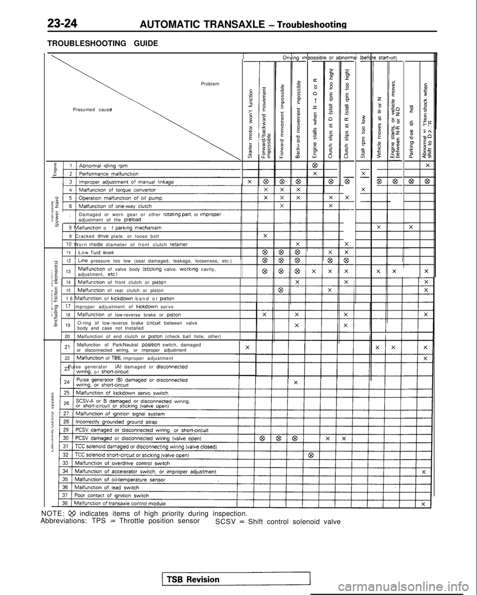
23-24AUTOMATIC TRANSAXLE - Troubleshooting
TROUBLESHOOTING GUIDE
T-----lO"ni31-
z.Ip.c
8Ea
=
s"oz6
E.
;In.ci!
a
-
F
X
-
-
X
77
c-
X
F-
i-
1g I”,PC-
ms?A
E
EEF.E053%
2
xsib-or z-
Pp
s E
a=g
n6
BE0.cY.20 (befl
-St.3-
zbaz
ti?BEa,fs
off)-
dI?f
s50>z6-0vi@zEiECE$,aZ5%-
-
7-
-
Ibr
I
Problem
Presumed causeTi3::-0 e
2Ts
y.=:,02 EF
g'5 +
v-60
F $2
s?
$=
2
$5
X
@63
X
X
I’
-
57-
-X-
-
G-- X
-
-X
X
e:,
Damaged or worn gear or other rotating part.
or rnproperadjustment of the preload
n
8 Malfunction of
parklng
mechamsm
9 Cracked drive plate. or loose bolt
10 Worn InsIde
diameter of front clutch retainer
11Low flutd
level
X
-
1z12 Line
pressure too low (seal damaged, leakage, looseness, etc.)E:o 13Malfunctton of valve body (sticking valve. worktng cavity,
j$adjustment, etc )XX
I
:?I14‘cMalfunction of front clutch or poston
)_O15Malfunction of rear clutch or pistoni;;E16 Malfunction of klckdown band or piston
le17 Improper adjustment of kickdown servoj318Malfunction of low-reverse brake or piston-6s 19 O-ring of low-reverse brake circuit between valve
body and case not Installed
20 Malfunction of end clutch or
piston (check ball hole, other)
2,Malfunction of Park/Neutral positjon switch, damaged
or disconnected wiring, or improper adjustment
22
Malfunction of TPS. or improper adjustment
23 Pulse generator
(A) damaged or disconnectedwlnng. or short&cut^
NOTE: Qo indicates items of high priority during inspection.
Abbreviations: TPS = Throttle position sensor SCSV = Shift control solenoid valve
Page 732 of 1273
23-26AUTOMATIC TRANSAXLE - Troubleshooting
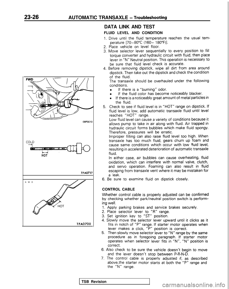
HOT
TFA0715
AW
D
TFA0700
DATA LINK AND TEST
FLUID LEVEL AND CONDITION
1. Drive until the
fluid
temperature
reaches the
usual tem-
perature
[70-80°C (160- 18O”F)l.
2. Place
vehicle
on level floor.
3. Move
selector
lever sequentially
to
every
position
to fill
torque
converter
and hydraulic circuit
with fluid,
then
place
lever in “N” Neutral position.
This operation is necessary
t0
be sure that fluid
level check is accurate.
4. Before
removing
dipstick,
wipe all dirt from area around
dipstick.
Then take out
the
dipstick
and check the
condition
of the
fluid.
The
transaxle
should be overhauled under the following
conditions.
l If there
is a “burning” odor.
l If the
fluid
color
has become
noticeably
blacker.
lIf there
is a noticeably
great
amount
of metal particles in
the
fluid.
5.Check to
see if fluid
level is in “HOT” range on dipstick.
If
fluid
level is low, add automatic
transaxle
fluid
until level
reaches “HOT” range.
Low
fluid
level can cause a variety of
conditions
because it
allows
pump
to
take
in air along with fluid. Air trapped in
hydraulic circuit
forms
bubbles
which
make fluid
spongy.
Therefore,
pressures
will be erratic. Improper filling
can also raise fluid level too
high. When
transaxle
has too
much fluid,
gears churn up foam and
cause same
conditions
which occur with low fluid
level, resulting
in accelerated deterioration
of
automatic
transaxle
fluid.
In
either
case, air bubbles
can cause overheating,
fluid
oxidation,
which can interfere
with normal valve, clutch,
and
servo
operation.
Foaming can also result
in fluid
escaping
from
transaxle
vent where it
may be mistaken
for
a leak.
6. Be
sure to
examine
fluid
on dipstick
closely.
CONTROL CABLE
Whether control
cable is properly
adjusted
can be confirmed
by
checking
whether park/neutral
position
switch is perform-
ing
well.
1.
Apply
parking brakes and service
brakes securely.
2. Place
selector
lever
to
“R” range.
3. Set ignition
key to
“ST” position.
4.
Slowly
move
the
selector
lever
upward
until it
clicks as it
fits in
notch of “P” range. If starter
motor
operates
when
lever makes a click, “P”
position
is correct.
5.Then slowly
move
selector
lever to “N” range by
the
same
procedure as in foregoing
paragraph. If starter
motor
operates
when selector
lever
fits in ‘IN”, “N” position
is correct.
6.
Also check to be sure the
vehicle
doesn’t
begin to move
and
the
lever
doesn’t
stop
between
P-R-N-D.
7. The control
cable is properly
adjusted if, as described
above,the
starter
motor
starts
at both the
“P” range and the
“N” range.
TSB Revision
Page 759 of 1273
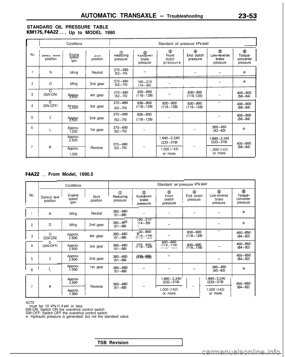
AUTOMATIC TRANSAXLE - Troubleshooting23-53
STANDARD OIL PRESSURE TABLE
KM175,
F4A22
. . .
Up to MODEL 1990
ConditionsStandard oil pressure kPa (psi)
N
O.1p -,-,..,-,,-_1Engine1Ch;J+1-0.1,,._,?...-1F%tclutch1E;;;;;;h1Lov$rse1To;;er13eleLL IfsYCIpositionspeedrpm
cl,1111positionneaucrng
pressurehlCI(aOWrIbrake
pressurepressure )Ipressure pressure
1NldlrngNeutral--*
2DIdling2nd gear 100-210
(14-30)
-
3(SWDON,Approx.830-900 830-900
400-600
--2,5004th gear
(118-128)
(118-128) (56-84)
(SWZFFI
Approx.3rd gear370-490830-900830-900 830-900
400-600-42.500
(52-70) (118-128)
(118-128)
(118-128)
(56-84)
52Approx.
2,5002nd gear370-490830-900 400-600-
(52-70) (118-128)
- (56-84)
-*6LApprox.1st gear370-4901,000
(52-70)-;g:gp
7R
A;pp56od(.
Approx.
1,000
Reverse370-490
(52-70) 1.640-2.240
1.640-2.240
(233-318)(233-318)--1.000 (142)1.OOO (I 42)or more
or moreF4A22
. . .From Model, 1990.5
ConditionsStandard 011 pressure kPa (Psi)
[email protected]“__l__^:__KrlrA,vrrnFrontEnd clutch
Low-reverseTorque-Select leve
brakeconverter
position pressure
‘ressurep-“cxm”1~ ,pressure
pressure
:rspeedcl,,,i;ne”“l;lily wmposition
pressureII
I I360-4801NIdlingNeutral(51~6P’2,--*--
TSB Revision
171 DIdling2nd gear360-4f (51-6b,
, \I
30?y;I;;p-*->i
30-900830-900450-650-1n-17RI- (118-128)(64-92)A2pPg4th gear360-480I I,.lY”-“Iv,(51-681
830-9004(SWZFF)A2pWg.3rdgear
(118-128)
,- .~,,,,“~.--,~.-lL”l,E%830-900-fllR-l='4g::;p
I I52
II
A2pg;.2nd gear~~~~~~p830-900-(118-128)-$g:;p
300-450
-*--”LApP&y.1stgear
(43-63)
1
ICI I
1 EEi2840 / _ 1 ‘~o~$~ ) 4iiIi;p7RReverse360-480
(51-68)
-1.000 (142)or more
NOTEmust be 10 kPa (I .4 psi) or less.
SW-ON: Switch ON the overdrive control switch SW-OFF: Switch OFF the overdrive control switch
*: Hydraulic pressure is generated, but not the standard value
Page 789 of 1273
AUTOMATIC TRANSAXLE - Service Adjustment Procedures23-83
I:
I’
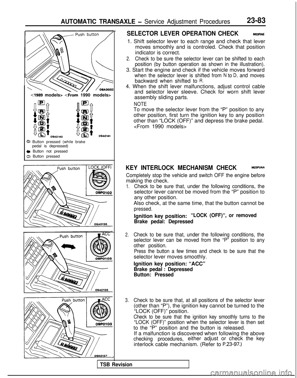
4989 models>
09A0140
6% Button pressed (while brakepedal is depressed)
c Button not pressed
0 Button pressed
SELECTOR LEVER OPERATION CHECKM23flAE
1. Shift selector lever to each range and check that lever
moves smoothly and is controled. Check that position
indicator is correct.
2.Check to be sure the selector lever can be shifted to each
position (by button operation as shown in the illustration).
3. Start the engine and check if the vehicle moves forward
when the selector lever is shifted from N to D, and moves
backward when shifted to R.
4. When the shift lever malfunctions, adjust control cable and selector lever sleeve. Check for worn shift lever
assembly sliding parts.
NOTE
To move the selector lever from the “P” position to any
other position, first turn the ignition key to any position
other than “LOCK (OFF)” and depress the brake pedal.
KEY INTERLOCK MECHANISM CHECKM23FUAA
Completely stop the vehicle and switch OFF the engine before
making the check.
1.Check to be sure that, under the following conditions, the
selector lever cannot be moved from the “P” position to
any other position.
Also check, at the same time, that the button cannot be
pressed.
Ignition key position:“LOCK (OFF)“, or removed
Brake pedal: Depressed
2.Check to be sure that, under the following conditions, the selector lever can be moved from the “P” position to any
other position.
Press the button a few times and check to be sure that the
selector lever moves smoothly.
Ignition key position: “ACC”
Brake pedal : Depressed
Button: Pressed
3.Check to be sure that, at all positions of the selector lever
(other than “P”), the ignition key cannot be turned to the
“LOCK (OFF)” position.
Check to be sure that the ignition key smoothly turns to the
“LOCK (OFF)” position when the selector lever is then set
to the “P” position and the button is released.
If a malfunction is discovered when following the above
checking procedures,either adjust or check the key
interlock cable mechanism. (Refer to
P.23-97.)
-I
TSB Revision
Page 790 of 1273
23-84AUTOMATIC TRANSAXLE - Service Adiustment Procedures
Brake
pedal
IOSM0045
A
iection A-A
Switch body
- 175133
12 mm (.47 in.)
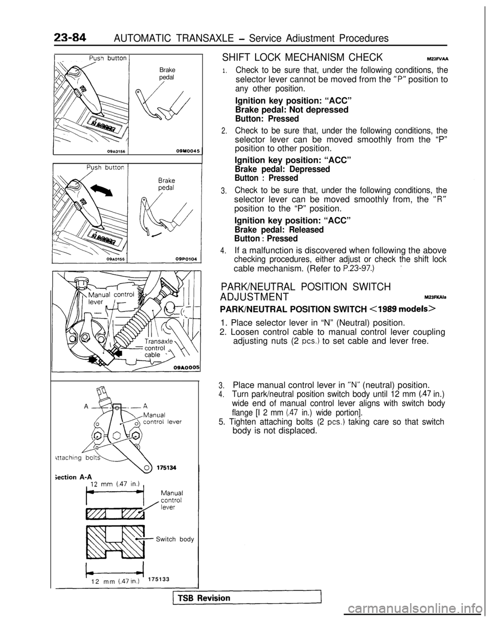
SHIFT LOCK MECHANISM CHECKMz3Fv~
1.
2.
3.
4.
Check to be sure that, under the following conditions, the
selector lever cannot be moved from the “P”
position to
any other position.
Ignition key position: “ACC”
Brake pedal: Not depressed
Button: Pressed
Check to be sure that, under the following conditions, the
selector lever can be moved smoothly from the “P”
position to other position.
Ignition key position: “ACC”
Brake pedal: Depressed
Button : Pressed
Check to be sure that, under the following conditions, the
selector lever can be moved smoothly from, the “I?”
position to the “P” position.
Ignition key position: “ACC”
Brake pedal: Released
Button
: Pressed
If a malfunction is discovered when following the above
checking procedures, either adjust or check the shift lock
cable mechanism. (Refer to P.23-97.)’
PARK/NEUTRAL POSITION SWITCH
ADJUSTMENT M23FKAla
PARK/NEUTRAL POSITION SWITCH
<1989 models>
1. Place selector lever in “N” (Neutral) position.
2. Loosen control cable to manual control lever coupling adjusting nuts (2
PCS.) to set cable and lever free.
3.Place manual control lever in “N” (neutral) position.
4.Turn park/neutral position switch body until 12 mm (.47 in.)
wide end of manual control lever aligns with switch body
flange [I 2 mm (.47 in.) wide portion].
5. Tighten attaching bolts (2 PCS.) taking care so that switch
body is not displaced.
Page 819 of 1273

PROPELLER SHAFT - Propeller Shaft25-5
,.\
@Jjiig\ .!’
Lower
UpperSpacer
1060012 2.
3.
4.
Do not lower rear end of the vehicle as the oil will flow
out of the transfer.
Be cautious to avoid damage to the oil seal lip of the
transfer.
Use the special tool provided as a cover to prevent the
entry of foreign objects into the transfer.
INSPECTIONM2SGCAH
l Check the sleeve yoke, center yoke and flange yoke for wear, damage or cracks.
l Check the propeller shaft yokes for wear, damage or
cracks.
lCheck the propeller shaft for bends, twisting or damage.
l Measure the propeller shaft runout
with a dial indicator.
Limit:
Front propeller shaft
0.6 mm (.024 in.) or less
Center propeller shaft0.6 mm (.024 in.) or less
Rear propeller shaft0.6 mm (.024 in.) or less
NOTE
Set the V-blocks as much as possible to the end of the
shaft. Measure deflection at the center of the shaft.
l Check the universal joints for smooth operation in all directions.
l Check
the’center bearing for smooth movement.
l Check the center bearing mounting rubber for damage or
deterioration.
SERVICE POINTS OF INSTALLATIONM25GDAN
3. INSTALLATION OF SPACER/P. INSULATOR
install spacers and insulators as indicated in the illustration.
Caution
When installing the center bearing, assemble the same
spacers as removed from it (or new spacers of equal
thickness).
1 TSB Revision
Page 820 of 1273
25-6PROPELLER SHAFT - Propeller Shaft
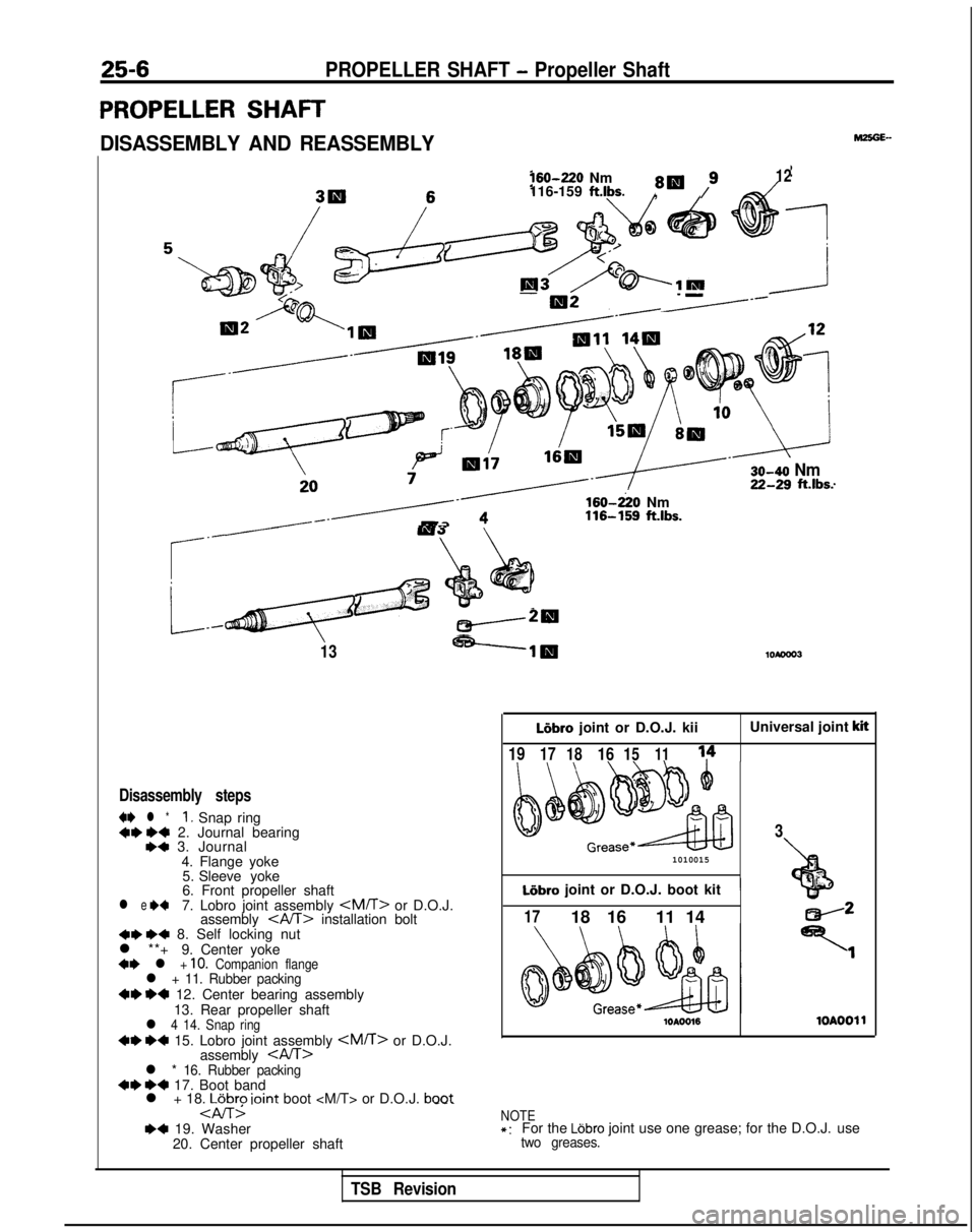
PROPELLER SHAFT
DISASSEMBLY AND REASSEMBLY160-220
Nm
8W /912116-159 ft.lbs.,
-
-I=------ 30-40
NmZG?~ ft.lbs.
/------d3
rQ”‘ ;+’
4s
.
G
*I4 :
_cw20
13-----lig
Disassembly steps
4I)
l *I, Snap ring+* I)+ 2. Journal bearing,a 3. Journal
4. Flange yoke5. Sleeve yoke
6. Front propeller shaft
l e +47. Lobro joint assembly
assembly
l **+ 9. Center yoke
+* l + 10. Companion flangel + 11. Rubber packing~~ ~~ 12. Center bearing assembly
13. Rear propeller shaft
l 4 14. Snap ring~~ ~~ 15. Lobro joint assembly
assembly
l + 18. LGbro ioint boot
--. 160-220
Nm 116-159
ft.lbs. LIbro
joint or D.O.J. kii Universal joint
kit
1917
18161511
1010015
Liibro joint or D.O.J. boot kit1
3
+bf ”
1718 16 11 14
lOAOO161OAOOll
NOTE*:For the Ldbro joint use one grease; for the D.O.J. usetwo greases.
TSB Revision
Page 832 of 1273
26-2
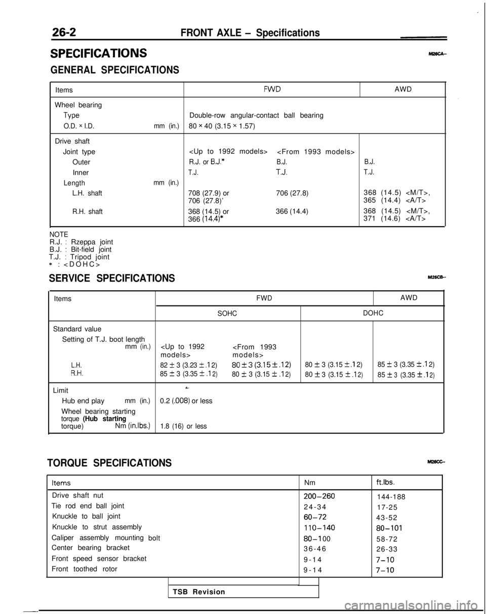
SPECIFICATIONS
FRONT AXLE - Specifications
GENERAL SPECIFICATIONS
Items
Wheel bearing Type
O.D. x I.D.
Drive shaft
Joint type Outer
Inner
Length L.H. shaft
R.H. shaft
FWDAWD
Double-row angular-contact ball bearing
mm (in.)80 x 40 (3.15 x 1.57)
R.J. or B.J.*B.J. B.J.
T.J.T.J.T.J.
mm (in.)
708 (27.9) or
706 (27.8)368 (14.5)
706 (27.8)’ 365 (14.4)
368 (14.5) or 366 (14.4)368 (14.5)
366
(14.4)*371 (14.6)
NOTER.J. : Rzeppa joint
B.J. : Bit-field joint
T.J. : Tripod joint *:
>
SERVICE SPECIFICATIONS
ItemsFWDAWD
SOHC
DOHC
Standard value
Setting of T.J. boot length mm
(in.)
L.H.82 + 3 (3.23 k .I 2)80f3 (3.15f.12)80 + 3 (3.15 f .I 2)
85 f 3 (3.35 k .I 2)
R.H.85 III 3 (3.35 +
.I2)80 IL 3 (3.15 f.I2)80f3
(3.15f .I2)85f3(3.3531
.I2)
LimitX.
Hub end playmm (in.)0.2 (.008) or less
Wheel bearing starting
torque (Hub startingtorque) Nm (inlbs.)1.8 (16) or less
TORQUE SPECIFICATIONS
ItemsNmftlbs.
Drive shaft nut200-260144-188
Tie rod end ball joint 24-3
4
17-25
Knuckle to ball joint
60-7243-52
Knuckle to strut assembly
110-14080-101
Caliper assembly mounting bolt80-I 0058-72
Center bearing bracket 36-4
6
26-33
Front speed sensor bracket 9-14
7-10
Front toothed rotor9-1
4
7-10
TSB Revision
-_