set MITSUBISHI GALANT 1989 Service Manual PDF
[x] Cancel search | Manufacturer: MITSUBISHI, Model Year: 1989, Model line: GALANT, Model: MITSUBISHI GALANT 1989Pages: 1273, PDF Size: 37.62 MB
Page 540 of 1273
13-398
AUTO-CRUISE CONTROL SYSTEM - Setice Adjustment procedures
03*02.5*
1
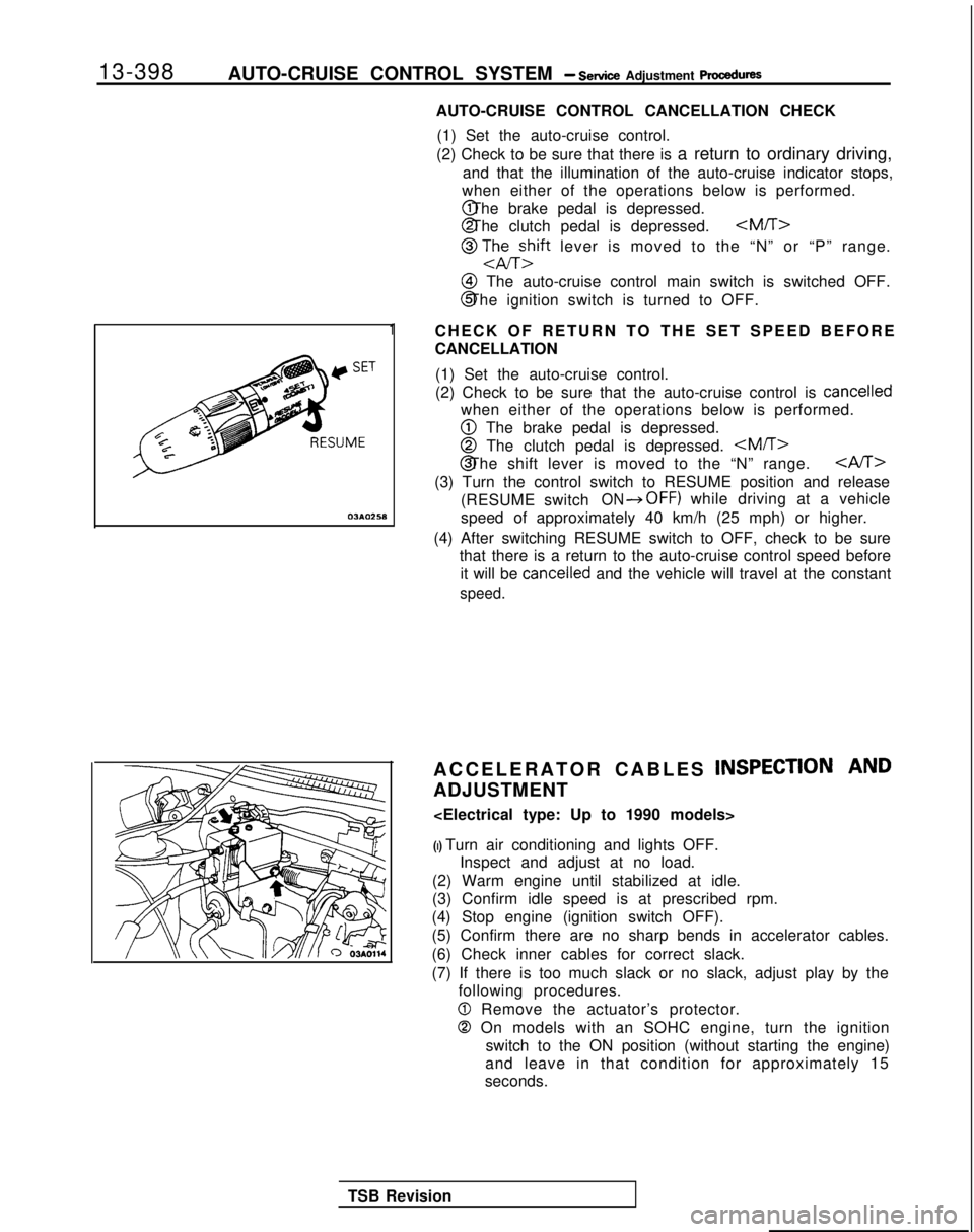
AUTO-CRUISE CONTROL CANCELLATION CHECK
(1) Set the auto-cruise control.
(2) Check to be sure that there is a return to ordinary driving,
and that the illumination of the auto-cruise indicator stops,
when either of the operations below is performed. @ The brake pedal is depressed.
@ The clutch pedal is depressed.
@ TJhEzift lever is moved to the “N” or “P” range.
@I The auto-cruise control main switch is switched OFF.
@ The ignition switch is turned to OFF.
CHECK OF RETURN TO THE SET SPEED BEFORE
CANCELLATION (1) Set the auto-cruise control.
(2) Check to be sure that the auto-cruise control is
cancelled
when either of the operations below is performed.
@ The brake pedal is depressed.
@ The clutch pedal is depressed.
CAST>
(3) Turn the control switch to RESUME position and release
(RESUME switch
ON*OFF) while driving at a vehicle
speed of approximately 40 km/h (25 mph) or higher.
(4) After switching RESUME switch to OFF, check to be sure that there is a return to the auto-cruise control speed before
it will be
cancelled and the vehicle will travel at the constant
speed.
ACCELERATOR CABLES INSPECTION AND
ADJUSTMENT
(I) Turn air conditioning and lights OFF. Inspect and adjust at no load.
(2) Warm engine until stabilized at idle.
(3) Confirm idle speed is at prescribed rpm.
(4) Stop engine (ignition switch OFF).
(5) Confirm there are no sharp bends in accelerator cables.
(6) Check inner cables for correct slack.
(7) If there is too much slack or no slack, adjust play by the following procedures.
0 Remove the actuator’s protector.
0 On models with an SOHC engine, turn the ignition
switch to the ON position (without starting the engine)
and leave in that condition for approximately 15
seconds.
TSB Revision
Page 541 of 1273
AUTO-CRUISE CONTROL SYSTEM - Setice Adjustment ~rccedures13-399
Accelerator cable B
Intake manifold
plenum
VAdjusting bolts07A0021
Throttle -.--
StopperCloskd throttleposition swrtch 03~0278
Acceleratorcable A
I
03A0271
-Ai+1-2 mm (.04-.08
in.)
TSB Revision
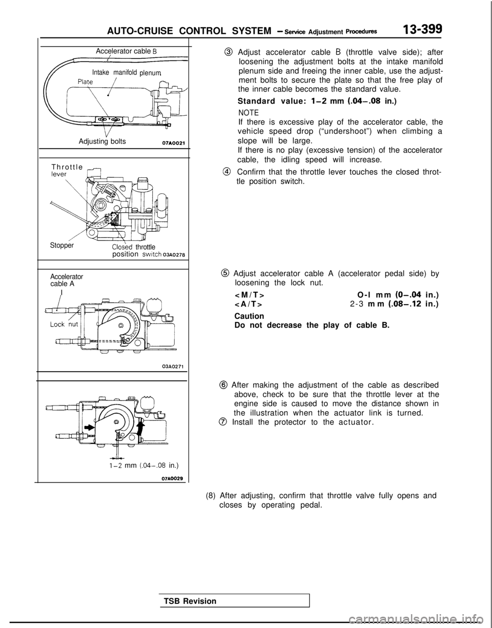
@ Adjust accelerator cable B (throttle valve side); after
loosening the adjustment bolts at the intake manifold
plenum side and freeing the inner cable, use the adjust-
ment bolts to secure the plate so that the free play of
the inner cable becomes the standard value.
Standard value:
l-2 mm (.04-.08 in.)
NOTE
If there is excessive play of the accelerator cable, the
vehicle speed drop (“undershoot”) when climbing a
slope will be large.
If there is no play (excessive tension) of the accelerator
cable, the idling speed will increase.
@Confirm that the throttle lever touches the closed throt-
tle position switch.
@ Adjust accelerator cable A (accelerator pedal side) by loosening the lock nut.
O-l mm
(O-.04 in.)
>
2-3
mm
(.08-.12 in.)
Caution
Do not decrease the play of cable B.
@ After making the adjustment of the cable as described above, check to be sure that the throttle lever at the
engine side is caused to move the distance shown in
the illustration when the actuator link is turned.
@ Install the protector to the actuator.
(8) After adjusting, confirm that throttle valve fully opens and closes by operating pedal.
Page 543 of 1273
AUTO-CRUISE CONTROL SYSTEM - Setice Adiustment Procedures13-401
16AO192
--
Ib/-
SJy-
iii
3 1
24
J
14LO142
INDIVIDUAL PARTS INSPEtiTION
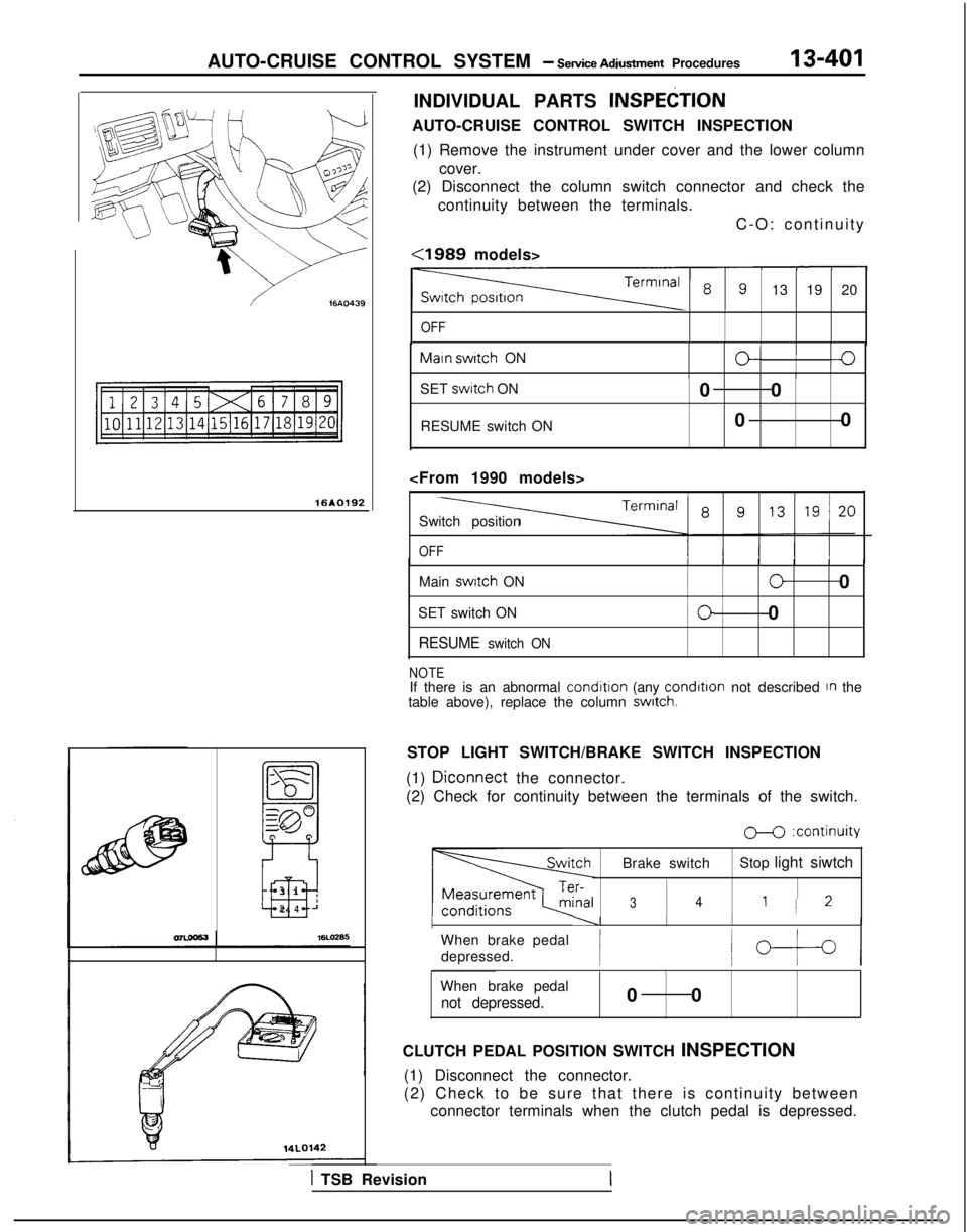
AUTO-CRUISE CONTROL SWITCH INSPECTION
(1) Remove the instrument under cover and the lower column cover.
(2) Disconnect the column switch connector and check the
continuity between the terminals.
C-O: continuity
<1989 models>
13 19 20
OFF Maln
switch
ON
O/I0IIIISET swttch
ON
RESUME switch ON 0 0
0 0
OFF
Main switch
ON
SET switch ON
RESUME switch ON
00
00
NOTEIf there is an abnormal condition
(any condltlon
not described In the
table above), replace the column switch.
STOP LIGHT SWITCH/BRAKE SWITCH INSPECTION
(1)
Diconnect the connector.
(2) Check for continuity between the terminals of the switch.
M :continuity
Brake switch Stop light siwtch
341 1 2
I----II I
When brake pedal
depressed.
/b-t-4
When brake pedal
not depressed.0 0
CLUTCH PEDAL POSITION SWITCH INSPECTION (1) Disconnect the connector.
(2) Check to be sure that there is continuity between connector terminals when the clutch pedal is depressed.
1 TSB Revision
Page 547 of 1273
AUTO-CRUISE CONTROL SYSTEM - Sewice Adjustment Procedures
ECU connector terminals
19171513ll><7531
2018161412 101 98642
16A1060
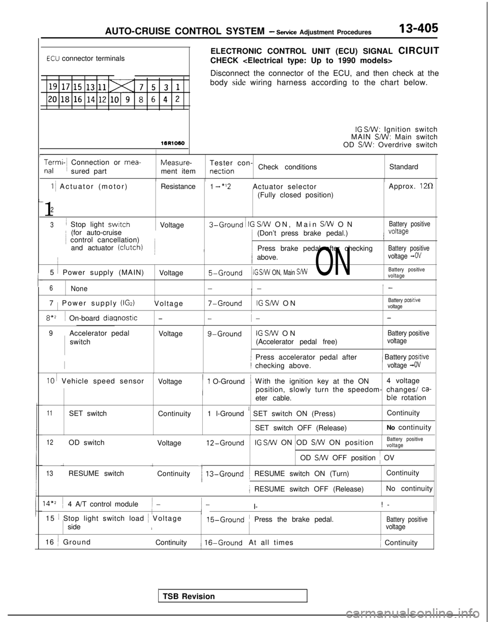
ELECTRONIC CONTROL UNIT (ECU) SIGNAL CIRCUIT
CHECK
Disconnect the connector of the ECU, and then check at the
body side wiring harness according to the chart below.
IG SW: Ignition switch
MAIN SW: Main switch
OD SMI: Overdrive switch
Termi-~ Connection or mea-
nal
~
sured part Measure-
Tester con-
ment item nection
Check conditions
Standard
I-
I-
1 ~
Actuator (motor) Resistance1 - “‘2Actuator selector Approx. 120
(Fully closed position)
1
2
3I Stop light switchVoltage3-Ground ~
IG S/W ON, Main SW O
N
Battery positive
~
(for auto-cruise ~
control cancellation)
j )
i (Don’t press brake pedal.)j voltage
and actuator (clutch)I Press brake pedal after checkingBattery positive
5 1 Power supply (MAIN)
/ above.voltage -0V
Voltage5-Ground
1 IG S/W
ON, Main S/W ONBattery positive
voltage
6None-i -i-
7 1
Power supply (IGz)Voltag
e
7-GroundIG SfW O
N
Battery positive
voltage
8*z ~
On-board diagnostic--i- -
TSB Revision
9Accelerator pedal Voltageg-GroundIG SW O
N
Battery positive
switch
(Accelerator pedal free)voltage
1 Press accelerator pedal after/ Battery positive
II checking above.[voltage -0V
IO I Vehicle speed sensor
Voltage1 O-Ground’ W
ith the ignition key at the ON
’ ~
4 voltage
position, slowly turn the speedom- changes/
ca-
eter cable. ble
rotation
11SET switch
Continuity1 l-Ground ’ SET switch ON (Press) Continuity
SET switch OFF (Release) No continuity
12OD switch
13RESUME switch 1
Voltage
Continuity
12-GroundIG SNV ON OD SW ON position
Battery positive
voltage
OD
SW OFF position ~
OV
13-Ground ~
RESUME switch ON (Turn) Continuity
; RESUME switch OFF (Release)
No continuity
14’2 ~
4 A/T control module( -/- I- !
-
I/15 1 Stop light switch load
~
Voltage15-Ground’ Press the brake pedal.Battery positiveside/voltage
16 j Ground
Continuity1 16-GroundAt all times ~
Continuity
Page 549 of 1273

AUTO-CRUISE CONTROL SYSTEM - Setice Adjustment procedures13-407
=\
07A005.1
Controlvalve
L2
07AOO50
AUTO-CRUISE CONTROL VACUUM PUMP INSPECTION
Inspection of solenoid valves (control valve, release valve)
(1) Remove the auto-cruise control vacuum pump connector.
(2) Measure the resistance value between terminals
0-0
and between 0-0.
Standard value: 50-60 Q
(3) Check that the solenoid valve makes an operating noise
when batten/ voltage is impressed between terminals
0-0 and between 0-0.
(4) If there is a malfunction of the solenoid valve, replace the
auto-cruise control vacuum pump assembly.
Motor inspection
(1) Remove the auto-cruise control vacuum pump connector.
(2) Check that the motor revolves when battery voltage is impressed between terminals
@-0.
TSB Revision ACTUATOR INSPECTION
(1) Remove the actuator.
(2) Apply negative pressure to the actuator with the vacuum pump and check that the holder moves more than 35 mm
(1.38 in.). In addition, check that there is no change in the
position of the holder when negative pressure is main-
tained in that condition.
(3) First install the actuator and then inspect and adjust the cruise control cable (Refer to
P.13-394.)
VEHICLE-SPEED SENSOR INSPECTION
Refer to GROUP
54-Meters and Gauges for checking of
vehicle speed sensor.
ACCELERATOR SWITCH INSPECTION
Refer to GROUP
23-Troubleshooting.
Page 557 of 1273
COOLING - Special TooVTroubleshooting
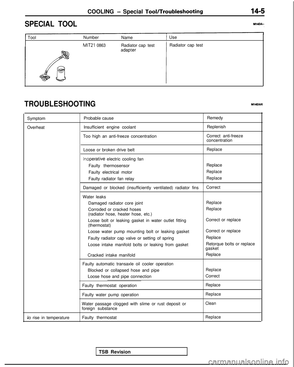
SPECIAL TOOL
1 Tool
Number
Name1 Use
MIT21 0863Radiator cap test Radiator cap test
TROUBLESHOOTINGM14EAAI
Symptom
Overheat Probable cause
Insufficient engine coolant
Too high an anti-freeze concentration Remedy
Replenish
Correct anti-freeze
concentration
Loose or broken drive belt
Replace Inoperative
electric cooling fan
Faulty thermosensor Replace
Faulty electrical motor
Replace
Faulty radiator fan relayReplace
Damaged or blocked (insufficiently ventilated) radiator fins Correct
Water leaks Damaged radiator core joint
Replace
Corroded or cracked hosesReplace
(radiator hose, heater hose, etc.)
Loose bolt or leaking gasket in water outlet fitting
(thermostat)
Loose water pump mounting bolt or leaking gasket
Faulty radiator cap valve or setting of spring
Loose intake manifold bolts or leaking from gasket
Cracked intake manifold
Faulty automatic transaxle oil cooler operation Blocked or collapsed hose and pipe
Loose hose and pipe connection
Faulty thermostat operation
Faulty water pump operation
Water passage clogged with slime or rust deposit or
foreign substance Correct or replace
Correct or replace
Replace
Retorque bolts or replace
gasket
Replace
Replace
Correct
Replace
Replace
Clean
Jo rise in temperature Faulty thermostatReplace
TSB Revision
Page 611 of 1273
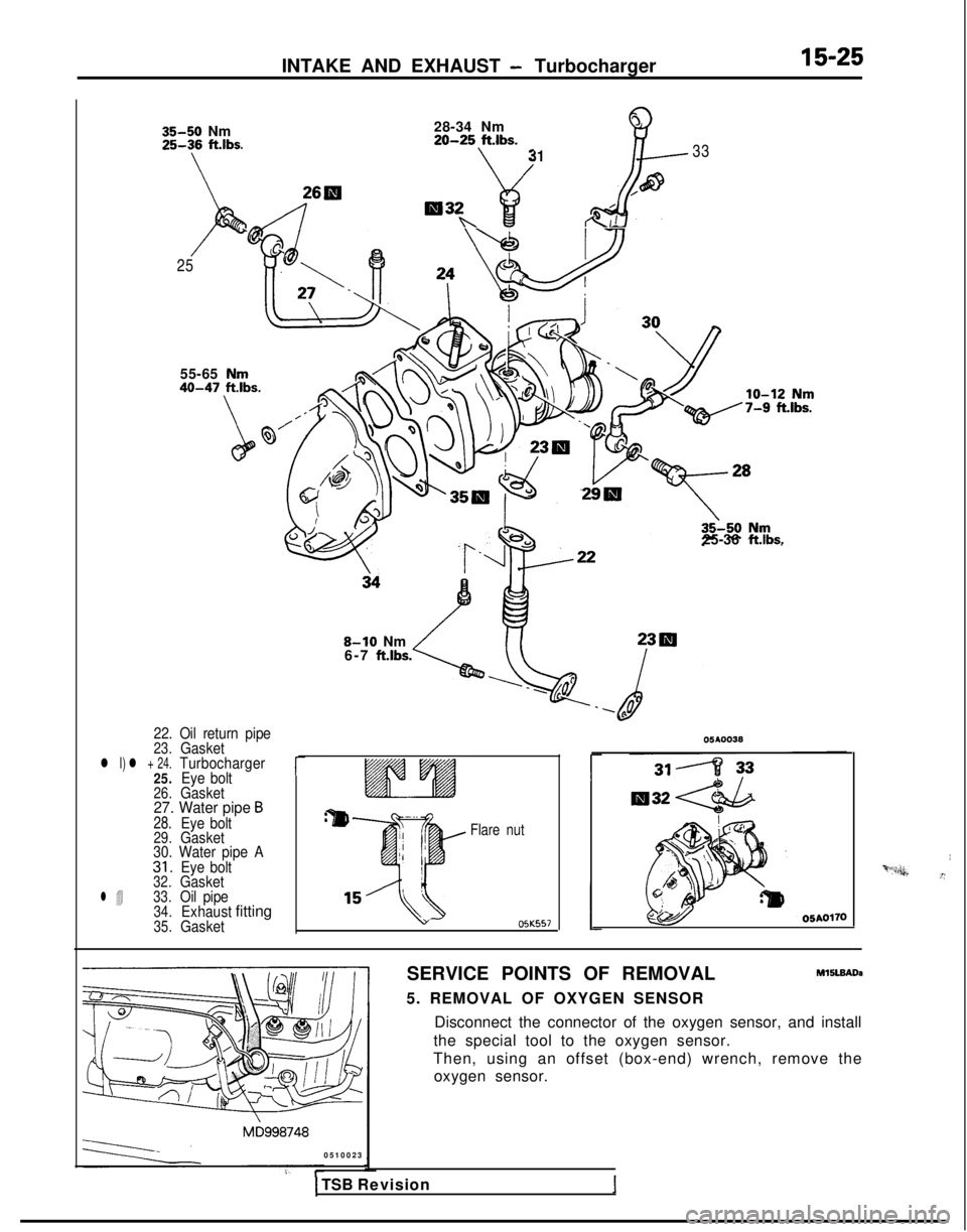
INTAKE AND EXHAUST - Turbocharger15-25
35-50 Nm
25-3\6 fubs*
28-34 Nm
920-25 ftlbs.
3133
26H,a
/IW32Rk .p&
/25
55-65
40-47
25-36 ftlbs.
22. Oil return pipe23.Gasketl I) l + 24.Turbocharger
25. Eye bolt
26.Gasket27. Water pipe B28.Eye bolt29.Gasket
30. Water pipe A
31.Eye bolt32.Gasketl 433.Oil pipe34.Exhaustfitting35.Gasket
r
8-10 Nm
6-7 ft.lbs.
Flare nut OJK557
SERVICE POINTS OF REMOVAL
M15lBAoa
5. REMOVAL OF OXYGEN SENSOR Disconnect the connector of the oxygen sensor, and install
the special tool to the oxygen sensor.
Then, using an offset (box-end) wrench, remove the oxygen sensor.
0510023
I‘“*“n,&.”
1 TSB Revision
Page 613 of 1273
INTAKE AND EXHAUST -Exhaust Manifold (SOHC-8 VALVE>15-27
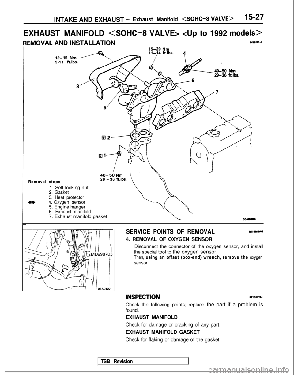
EXHAUST MANIFOLD
IEMOVAL AND INSTALLATIONYSNA-A
15-20
Nm
9-11 ftlbs.
40-50 Nm
Removal steps29 - 36 ft.lbs.
1. Self locking nut2. Gasket
3. Heat protector
a*4. Oxygen sensor
5. Engine hanger6. Exhaust manifold7. Exhaust manifold gasket
SERVICE POINTS OF REMOVAL MlSNBAG
4. REMOVAL OF OXYGEN SENSOR
Disconnect the connector of the oxygen sensor, and install
the special tool to the oxygen sensor.
Then, using an offset (box-end) wrench, remove the oxygen
sensor.
INSPECTldNMllNCAL
Check the following points; replace the part if a problem is
found.
EXHAUST MANIFOLD
Check for damage or cracking of any part.
EXHAUST MANIFOLD GASKET
Check for flaking or damage of the gasket.
TSB Revision1
Page 615 of 1273
INTAKE AND EXHAUST - Exhaust Manifold
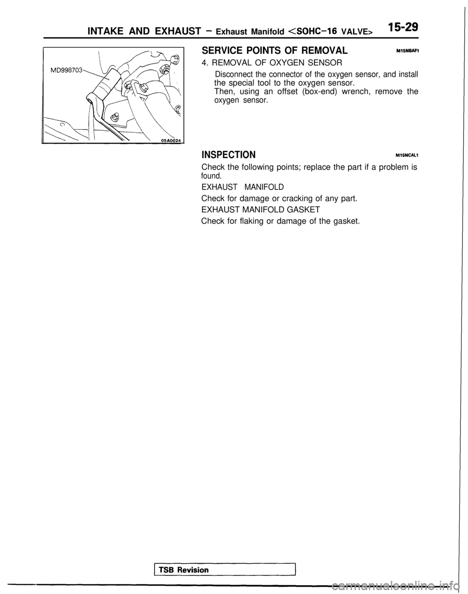
SERVICE POINTS OF REMOVAL
MlBNBAFl
4. REMOVAL OF OXYGEN SENSOR
Disconnect the connector of the oxygen sensor, and install
the special tool to the oxygen sensor.
Then, using an offset (box-end) wrench, remove the
oxygen sensor.
INSPECTION MlSNCALl
Check the following points; replace the part if a problem is
found.
EXHAUST MANIFOLD
Check for damage or cracking of any part.
EXHAUST MANIFOLD GASKET
Check for flaking or damage of the gasket.
Page 616 of 1273
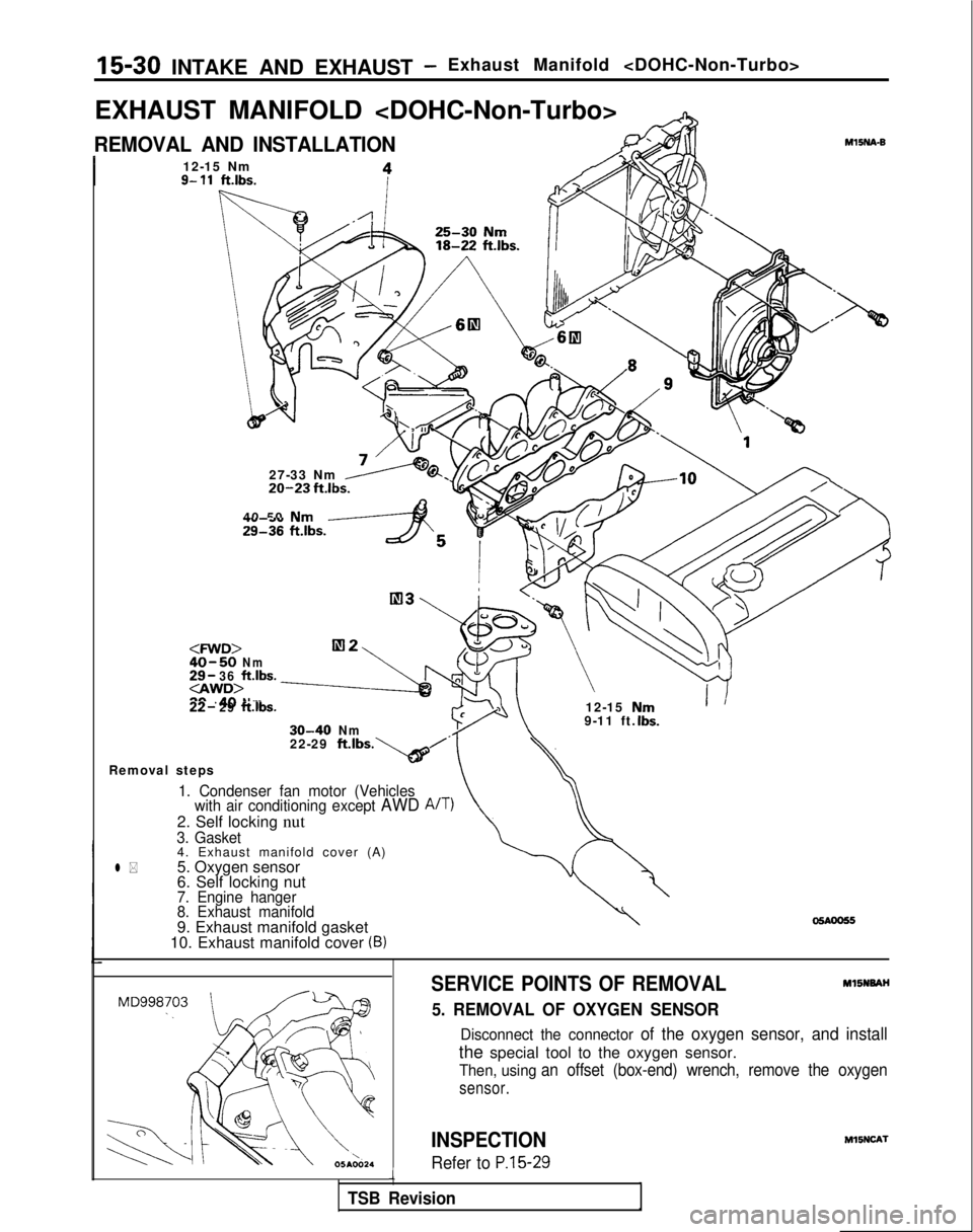
15-30 INTAKE AND EXHAUST -Exhaust Manifold
EXHAUST MANIFOLD
REMOVAL AND INSTALLATION
I12-15 Nm9- 11ft.lbs.
27-33 Nm20-23 fklbs.
40 50 Nm29136 ft.lbs.yAS
30-40Nm9-11 ft.
\
UrnIbs.
MlINA-B
22-29 ft.lbs
Removal steps*b’.
1. Condenser fan motor (Vehicles with air conditioning except AWD A/T)
2. Self locking nut3. Gasket4. Exhaust manifold cover (A)
l *5. Oxygen sensor
6. Self locking nut
7. Engine hanger
8. Exhaust manifold
9. Exhaust manifold gasket
10. Exhaust manifold cover (B)
SERVICE POINTS OF REMOVALMl5NNAH
5. REMOVAL OF OXYGEN SENSOR
Disconnect the connector of the oxygen sensor, and install
the special tool to the oxygen sensor.
Then, using an offset (box-end) wrench, remove the oxygen
sensor.
INSPECTION
Refer to P.15-29i
TSB Revision M15NCA-l