MITSUBISHI iMiEV 2013 Owner's Manual (in English)
Manufacturer: MITSUBISHI, Model Year: 2013, Model line: iMiEV, Model: MITSUBISHI iMiEV 2013Pages: 258, PDF Size: 13 MB
Page 101 of 258
Instruments...................................................................................
4-02
Indication and warning lamps .......................................................4-08
Indication lamps ........................................................................... 4-09
Warning lamps .............................................................................. 4-09
Combination headlamps and dipper switch ..................................4-11
Headlamp levelling switch ........................................................... 4-13
Turn-signal lever...........................................................................4-14
Hazard warning flasher switch ..................................................... 4-15
Fog lamp switch............................................................................4-15
Wiper and washer switch .............................................................. 4-16
Rear window demister switch.......................................................4-18
Horn switch...................................................................................4-19 Instruments and controls
4
OHAE13E1
Page 102 of 258
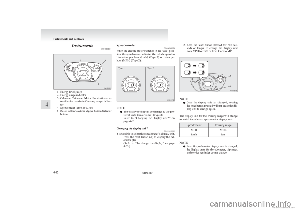
Instruments
E005001012511- Energy level gauge
2-
Energy usage indicator
3- Odometer/Tripmeter/Meter illumination con- trol/Service reminder/Cruising range indica-
tor
4- Speedometer (km/h or MPH)
5- Reset button/Daytime dipper button/Selector button Speedometer
E00500201050
When
the electric motor switch is in the “ON” posi-
tion, the speedometer indicates the vehicle speed in
kilometers per hour (km/h) (Type 1) or miles per
hour (MPH) (Type 2).
Type 1 Type 2 NOTE
l The
display setting can be changed to the pre-
ferred units (km or miles) (Type 2).
Refer to “Changing the display unit*” on
page 4-02.
Changing the display unit* E00529500026
It is possible to select the speedometer’s display unit.
1. Press
the reset button (A) to display the od-
ometer (B).
(Refer to “To change the display” on page
4-03.) 2. Keep
the reset button pressed for two sec-
onds or longer to change the display unit
from MPH to km/h or from km/h to MPH. NOTE
l Once
the display unit has changed, keeping
the reset button pressed will not cause the dis-
play unit to change again.
The display unit for the cruising range will change
to match the selected speedometer display unit. Speedometer Cruising range
MPH Miles
km/h km NOTE
l Even
if speedometer display unit is changed,
the display units for the odometer, tripmeter,
and service reminder do not change. Instruments and controls
4-02
4
OHAE13E1
Page 103 of 258
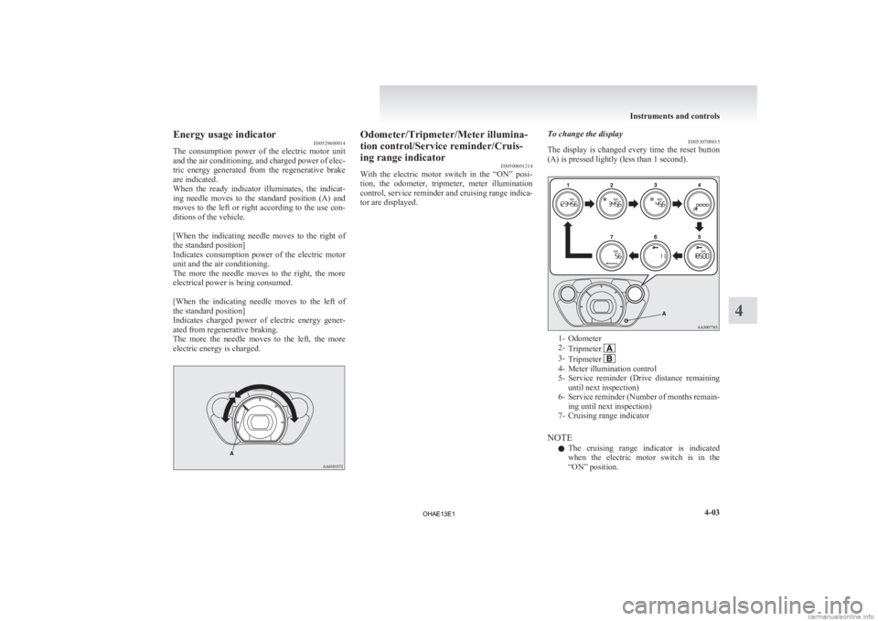
Energy usage indicator
E00529600014
The
consumption power of the electric motor unit
and the air conditioning, and charged power of elec-
tric energy generated from the regenerative brake
are indicated.
When the ready indicator illuminates, the indicat-
ing needle moves to the standard position (A) and
moves to the left or right according to the use con-
ditions of the vehicle.
[When the indicating needle moves to the right of
the standard position]
Indicates consumption power of the electric motor
unit and the air conditioning.
The more the needle moves to the right, the more
electrical power is being consumed.
[When the indicating needle moves to the left of
the standard position]
Indicates charged power of electric energy gener-
ated from regenerative braking.
The more the needle moves to the left, the more
electric energy is charged. Odometer/Tripmeter/Meter illumina-
tion control/Service reminder/Cruis-
ing range indicator
E00500601214
With
the electric motor switch in the “ON” posi-
tion, the odometer, tripmeter, meter illumination
control, service reminder and cruising range indica-
tor are displayed. To change the display
E00530700015
The
display is changed every time the reset button
(A) is pressed lightly (less than 1 second). 1- Odometer
2-
Tripmeter 3-
Tripmeter 4- Meter illumination control
5- Service
reminder (Drive distance remaining
until next inspection)
6- Service reminder (Number of months remain- ing until next inspection)
7- Cruising range indicator
NOTE l The cruising range indicator is indicated
when the electric motor switch is in the
“ON” position. Instruments and controls
4-03 4
OHAE13E1
Page 104 of 258
l
If there is no operation for about 10 seconds
when the meter illumination control or serv-
ice reminder is shown, the display returns to
the odometer.
Odometer E00530800016
The odometer indicates the total distance the vehi-
cle has travelled.
NOTE
l Even
if the electric motor switch is turned to
“ACC” or “LOCK”, the odometer will be dis-
played for about 30 seconds after the reset but-
ton is pressed.
Tripmeter E00530900017
The tripmeter indicates the distance travelled dur-
ing a particular trip or period.
There
are two tripmeter displays: Tripmeter and .
Tripmeter can be used to measure the distance
travelled
since the current trip began. At the same
time, Tripmeter can be used to measure the dis-
tance from an intermediate location.
NOTE
l Even
if the electric motor switch is turned to
the “ACC” or “LOCK” position, the tripme-
ter will be displayed for about 30 seconds af-
ter the reset button is pressed.
To reset the tripmeter
To return the display to “0”, press the reset button
(A) for more than 2 seconds. Only the currently dis-
played value will be reset. NOTE
l If
the auxiliary battery terminal is removed,
the memories for the tripmeter and
displays are erased and the displays return to
0.
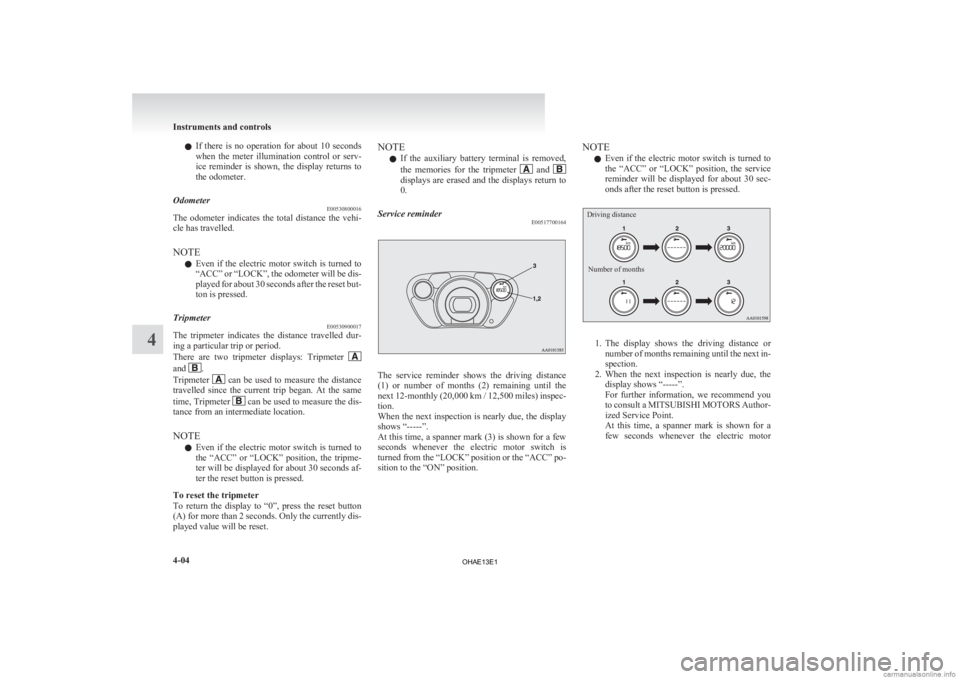
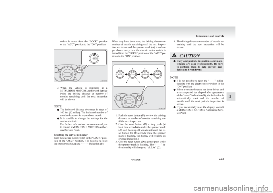
Service reminder E00517700164 The service reminder shows the driving distance
(1)
or number of months (2) remaining until the
next 12-monthly (20,000 km / 12,500 miles) inspec-
tion.
When the next inspection is nearly due, the display
shows “-----”.
At this time, a spanner mark (3) is shown for a few
seconds whenever the electric motor switch is
turned from the “LOCK” position or the “ACC” po-
sition to the “ON” position. NOTE
l Even
if the electric motor switch is turned to
the “ACC” or “LOCK” position, the service
reminder will be displayed for about 30 sec-
onds after the reset button is pressed.
Driving distance
Number of months 1. The
display shows the driving distance or
number of months remaining until the next in-
spection.
2. When the next inspection is nearly due, the display shows “-----”.
For further information, we recommend you
to consult a MITSUBISHI MOTORS Author-
ized Service Point.
At this time, a spanner mark is shown for a
few seconds whenever the electric motor Instruments and controls
4-04
4
OHAE13E1
Page 105 of 258
switch is turned from the “LOCK” position
or the “ACC” position to the “ON” position.
3. When the vehicle is inspected at a
MITSUBISHI MOTORS Authorized Service
Point, the driving distance or number of
months remaining until the next inspection
will be shown.
NOTE l The indicated distance decreases in steps of
100 km (62 miles). The indicated number of
months decreases in steps of one month.
l It is possible to change the settings for the
service reminder.
For further information, we recommend you
to consult a MITSUBISHI MOTORS Author-
ized Service Point.
Resetting the service reminder
With the electric motor switch in the “LOCK” posi-
tion or the “ACC” position, it is possible to reset
the spanner mark (A) and “------” indication (B). When they have been reset, the driving distance or
number
of months remaining until the next inspec-
tion are shown and the spanner mark (A) is no lon-
ger shown every time the electric motor switch is
turned from the “LOCK” position or the “ACC” po-
sition to the “ON” position. 1. Push
the reset button (D) to view the driving
distance or number of months remaining un-
til the next inspection.
2. Give the reset button (D) a long push (at least two seconds) to make the spanner mark
(A) start flashing. (If you do not touch the re-
set button for 10 seconds while the spanner
mark is flashing, the display will revert to its
original indication.)
3. Give the reset button (D) a gentle push while the spanner mark is flashing. The “------” in-
dication (B) will change to “cLEAr” (C). 4. The
driving distance or number of months re-
maining until the next inspection will be
shown. CAUTION
l
Daily
and periodic inspections and main-
tenance are your responsibility. Be sure
to perform them to help prevent acci-
dents and breakdowns.
NOTE l It
is not possible to reset the “------” indica-
tion (B) with the electric motor switch in the
“ON” position.
l When a certain distance has been driven and
a certain period has elapsed after appearance
of the “------” indication (B), the indication is
automatically reset and the number of
months until the next periodic inspection is
shown.
l If you accidentally reset the display, consult
a MITSUBISHI MOTORS Authorized Serv-
ice Point. Instruments and controls
4-05 4
OHAE13E1
Page 106 of 258
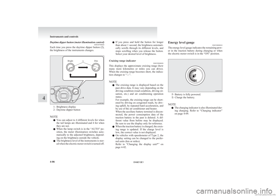
Daytime dipper button (meter illumination control)
E00529700028
Each
time you press the daytime dipper button (2),
the brightness of the instruments changes.
Bright Dim1- Brightness display
2-
Daytime dipper button
NOTE l You can adjust to 4 different levels for when
the tail lamps are illuminated and 4 for when
they are not.
l When the lamp switch is in the “AUTO” po-
sition, the meter illumination switches auto-
matically to the adjusted brightness, depend-
ing on the brightness outside the vehicle.
l The brightness level of the instruments is stor-
ed when the electric motor switch is turned off. l
If
you press and hold the button for longer
than about 1 second, the brightness automati-
cally scrolls through its different levels, and
stops scrolling when you release the button.
Select your desired level of brightness.
Cruising range indicator E00529900020
This displays the approximate cruising range (how
many
more kilometres or miles you can drive).
When the cruising range becomes short, the indica-
tion changes to “---”.
NOTE
l The cruising range is displayed based on the
past drive data. It may vary depending on the
driving condition (road condition, driving sit-
uation, etc.) and air conditioning operation
status.
For example, the cruising range can be short-
ened by driving on congested roads, by driv-
ing uphill, by repeated hard acceleration, and
by use of the air conditioner and heater.
When the auxiliary battery terminal is discon-
nected, the power consumption data of the
traction battery in the past is deleted. A dif-
ferent value from before may be displayed.
Be sure to use the display only for reference.
l When the traction battery is charged, the cruis-
ing range is updated. If the charge level is
low, the correct value is not displayed.
l On vehicles with speedometer of Type 2, the
display setting can be changed to the prefer-
red units (km or miles).
Refer to “Changing the display unit*” on
page 4-02. Energy level gauge
E00530000018
The
energy level gauge indicates the remaining pow-
er in the traction battery during charging or when
the electric motor switch is in the “ON” position. F- Battery is fully powered.
E- Charge the battery.
NOTE l The
charging indicator is also illuminated dur-
ing charging. Refer to “Charging indicator”
on page 4-09. Instruments and controls
4-06
4
OHAE13E1
Page 107 of 258
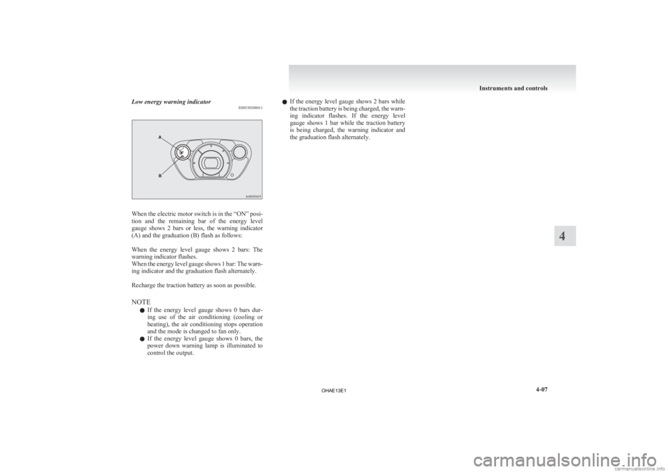
Low energy warning indicator
E00530300011When the electric motor switch is in the “ON” posi-
tion
and the remaining bar of the energy level
gauge shows 2 bars or less, the warning indicator
(A) and the graduation (B) flash as follows:
When the energy level gauge shows 2 bars: The
warning indicator flashes.
When the energy level gauge shows 1 bar: The warn-
ing indicator and the graduation flash alternately.
Recharge the traction battery as soon as possible.
NOTE
l If the energy level gauge shows 0 bars dur-
ing use of the air conditioning (cooling or
heating), the air conditioning stops operation
and the mode is changed to fan only.
l If the energy level gauge shows 0 bars, the
power down warning lamp is illuminated to
control the output. l
If
the energy level gauge shows 2 bars while
the traction battery is being charged, the warn-
ing indicator flashes. If the energy level
gauge shows 1 bar while the traction battery
is being charged, the warning indicator and
the graduation flash alternately. Instruments and controls
4-07 4
OHAE13E1
Page 108 of 258
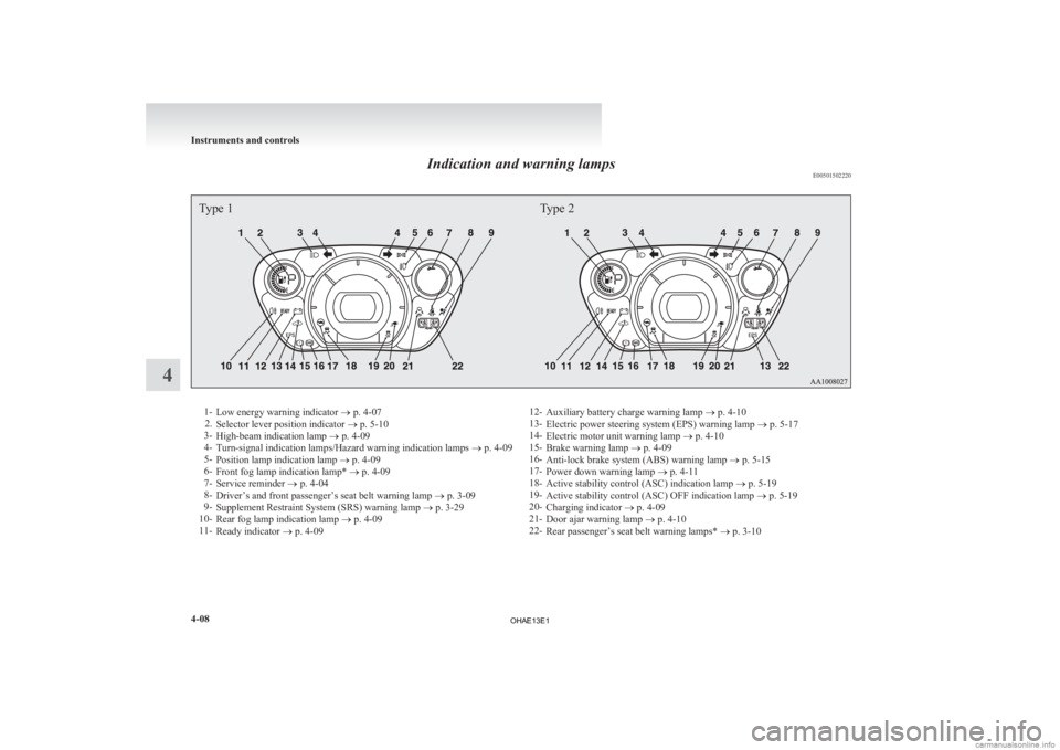
Indication and warning lamps
E00501502220Type 1Type 21-
Low energy warning indicator
® p. 4-07
2. Selector lever position indicator ® p. 5-10
3- High-beam indication lamp ® p. 4-09
4- Turn-signal indication lamps/Hazard warning indication lamps ® p. 4-09
5- Position lamp indication lamp ® p. 4-09
6- Front fog lamp indication lamp* ® p. 4-09
7- Service reminder ® p. 4-04
8- Driver’s and front passenger’s seat belt warning lamp ® p. 3-09
9- Supplement Restraint System (SRS) warning lamp ® p. 3-29
10- Rear fog lamp indication lamp ® p. 4-09
11- Ready indicator ® p. 4-09 12-
Auxiliary battery charge warning lamp ® p. 4-10
13- Electric power steering system (EPS) warning lamp ® p. 5-17
14- Electric motor unit warning lamp ® p. 4-10
15- Brake warning lamp ® p. 4-09
16- Anti-lock brake system (ABS) warning lamp ® p. 5-15
17- Power down warning lamp ® p. 4-11
18- Active stability control (ASC) indication lamp ® p. 5-19
19- Active stability control (ASC) OFF indication lamp ® p. 5-19
20- Charging indicator ® p. 4-09
21- Door ajar warning lamp ® p. 4-10
22- Rear passenger’s seat belt warning lamps* ® p. 3-10Instruments and controls
4-08 4
OHAE13E1
Page 109 of 258
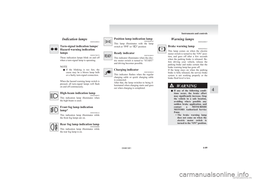
Indication lamps
E00501600012Turn-signal indication lamps/
Hazard warning indication
lamps
E00501700374
These
indication lamps blink on and off
when a turn-signal lamp is operating.
NOTE
l If the blinking is too fast, the
cause may be a blown lamp bulb
or a faulty turn-signal connection.
When the hazard warning lamp switch is
pressed, all turn-signal lamps will flash
on and off continuously. High-beam indication lamp
E00501800072
This
indication lamp illuminates when
the high-beam is used. Front fog lamp indication
lamp*
E00501900132
This
indication lamp illuminates while
the front fog lamps are on. Rear fog lamp indication lamp
E00502000084
This
indication lamp illuminates while
the rear fog lamp is on. Position lamp indication lamp
E00508900102
This
lamp illuminates with the lamp
switch at “ ” or “ ” position
Ready indicator
E00530100019
This
indicator illuminates when the elec-
tric motor switch is turned to “START”
and driving becomes possible. Charging indicator
E00530200010
This
indicator flashes when the regular
charging cable or quick charging cable
is connected.
After that, the lamp switches to being il-
luminated when charging starts and goes
out when charging is completed. Warning lamps
E00502400017 Brake warning lamp
E00502502621
This
lamp comes on when the electric
motor switch is turned to the “ON” posi-
tion, and goes off after a few seconds
when the parking brake is released. Be-
fore driving your vehicle, release the
parking brake and make certain that the
brake warning lamp has gone off.
If the lamp stays on when the parking
brake is fully released, the service brake
system is not working properly or the
brake fluid level is low. WARNING
l If
any of the following condi-
tions occur, the brake effort
may significantly increase. Stop
the vehicle in a safe location,
avoiding where possible any
sudden brake application, and
contact a MITSUBISHI
MOTORS Authorized Service
Point. • The brake warning lampdoes not come on when the
electric motor switch is
turned to the “ON” position. Instruments and controls
4-09 4
OHAE13E1
Page 110 of 258
WARNING
• The brake warning lamp does not illuminate while
the parking brake is applied
and the electric motor
switch is in the “ON” posi-
tion.
• The brake warning lamp stays on when the parking
brake is not applied.
NOTE l When
the brake warning lamp illu-
minates, the warning buzzer may
also sound.
l When the brake pedal has been re-
peatedly depressed over a short pe-
riod of time, the brake warning
lamp may come on and the brake
warning buzzer may sound. The
service brake system is working
normally, if the warning lamp
goes out and the buzzer stops
sounding after a few seconds.
l At times, you may hear the brake
electric vacuum pump for the pow-
er brakes operating when the
ready indicator illuminates or the
brake pedal is depressed.
This sound is normal and does not
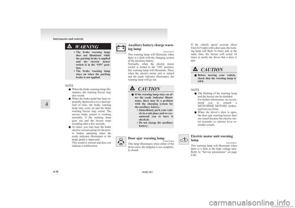
indicate a malfunction. Auxiliary battery charge warn-
ing lamp
E00502701251
This
warning lamp will illuminate when
there is a fault with the charging system
of the auxiliary battery.
Normally, when the electric motor
switch is turned to the “ON” position,
this warning lamp will illuminate. Then,
when the electric motor unit is started
and the ready indicator illuminates, the
warning lamp will go out. CAUTION
l
If the warning lamp stays on af-
ter
the ready indicator illumi-
nates, there may be a problem
with the charging system for
the auxiliary battery. • Immediately park your vehi-cle in a safe place and we rec-
ommend you to have it
checked.
• Do not charge the auxiliary battery. Door ajar warning lamp
E00503300840
This
lamp illuminates when either of the
doors (also, the tailgate) is not complete-
ly closed. If the vehicle speed exceeds about
8
km/h (5 mph) with a door ajar, the warn-
ing lamp will flash 16 times and, at the
same time, the buzzer will sound 16
times to notify the driver that a door is
ajar. CAUTION
l
Before
moving your vehicle,
check that the warning lamp is
OFF.
NOTE l The
flashing of the warning lamp
and the buzzer can be disabled.
For further information, we recom-
mend you to consult a
MITSUBISHI MOTORS Author-
ized Service Point.
l When the driver’s door is open,
the door ajar warning buzzer does
not sound because the electric mo-
tor reminder or selector lever re-
minder sounds. Electric motor unit warning
lamp
E00530400012
This
warning lamp will illuminate when
there is a fault at the high voltage area.
Refer to “Service precautions” on page
8-06. Instruments and controls
4-10
4
OHAE13E1