ignition MITSUBISHI L200 2015 (in English) User Guide
[x] Cancel search | Manufacturer: MITSUBISHI, Model Year: 2015, Model line: L200, Model: MITSUBISHI L200 2015Pages: 418, PDF Size: 25.8 MB
Page 86 of 418
WARNINGlDo not place stickers, labels or additional
trim on the seatback of either front seat.They could interfere with proper side air-bag inflation.
l Do not install seat covers on seats with
side airbags. Do not re-cover seats that have side airbags. This could interfere with proper side airbag inflation.
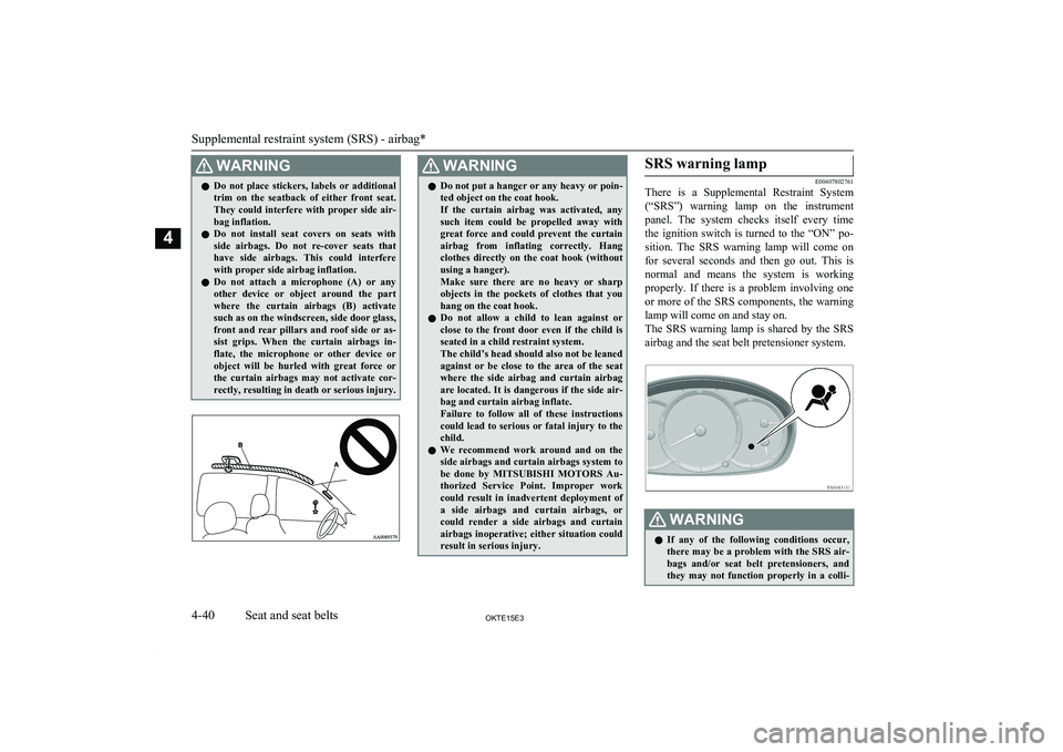
l Do not attach a microphone (A) or any
other device or object around the part
where the curtain airbags (B) activate such as on the windscreen, side door glass,
front and rear pillars and roof side or as- sist grips. When the curtain airbags in-
flate, the microphone or other device or object will be hurled with great force orthe curtain airbags may not activate cor-
rectly, resulting in death or serious injury.WARNINGl Do not put a hanger or any heavy or poin-
ted object on the coat hook.
If the curtain airbag was activated, any
such item could be propelled away with
great force and could prevent the curtain
airbag from inflating correctly. Hang clothes directly on the coat hook (withoutusing a hanger).
Make sure there are no heavy or sharp objects in the pockets of clothes that you
hang on the coat hook.
l Do not allow a child to lean against or
close to the front door even if the child is seated in a child restraint system.
The child’s head should also not be leaned
against or be close to the area of the seat where the side airbag and curtain airbag
are located. It is dangerous if the side air- bag and curtain airbag inflate.
Failure to follow all of these instructions
could lead to serious or fatal injury to the
child.
l We recommend work around and on the
side airbags and curtain airbags system to
be done by MITSUBISHI MOTORS Au-
thorized Service Point. Improper work could result in inadvertent deployment of
a side airbags and curtain airbags, or could render a side airbags and curtain airbags inoperative; either situation could
result in serious injury.SRS warning lamp
E00407802761
There is a Supplemental Restraint System
(“SRS”) warning lamp on the instrument panel. The system checks itself every time
the ignition switch is turned to the “ON” po- sition. The SRS warning lamp will come on
for several seconds and then go out. This is
normal and means the system is working properly. If there is a problem involving one
or more of the SRS components, the warning
lamp will come on and stay on.
The SRS warning lamp is shared by the SRS airbag and the seat belt pretensioner system.
WARNINGl If any of the following conditions occur,
there may be a problem with the SRS air- bags and/or seat belt pretensioners, and they may not function properly in a colli-
Supplemental restraint system (SRS) - airbag*
4-40OKTE15E3Seat and seat belts4
Page 87 of 418
WARNINGsion or may suddenly activate without a
collision:
• Even when the ignition switch is
in“ON” position, the SRS warning lamp does not come on or it remains
on.
• The SRS warning lamp comes on while
driving.
The SRS airbags and seat belt pretension- ers are designed to help reduce the risk of
serious injury or death in certain colli- sions. If either of the above conditions oc-
curs, immediately have your vehicle checked by a MITSUBISHI MOTORS
Authorized Service Point.SRS servicing
E00407901244
WARNINGl We recommend any maintenance per-
formed on or near the components of the
SRS to be performed by a MITSUBISHI
MOTORS Authorized Service Point.
Improper work on the SRS components
or wiring could result in inadvertent de- ployment of the airbags, or could render
the SRS inoperative; either situation could result in serious injury.WARNINGl Do not modify your steering wheel, seat
belt retractor or any other SRS compo- nents. For example, replacement of the
steering wheel, or modifications to the
front bumper or body structure can ad- versely affect SRS performance and lead
to possible injury.
l If your vehicle has sustained any damage,
we recommend you to have the SRS in- spected to ensure it is in proper workingorder.
l On vehicles equipped with side airbags,
do not modify your front seats, centre pil- lar and centre console.
It can adversely affect SRS performance and lead to possible injury.
Also, if you have found any tear or open
seam in the seat fabric at the portion near the side airbag, we recommend you to
have the seat inspected.
l On vehicles with the curtain airbags, if
you have found any scratch, crack or
damage to the portion of the front and rear pillars and roof side rail, we recom-
mend you to have the SRS inspected by a MITSUBISHI MOTORS Authorized
Service Point.NOTEl When you transfer ownership of the vehicle
to some other person, we urge you to alert
the new owner that it is equipped with the SRS and refer the new owner to the applica- ble section in this owner’s manual.
l If you junk or scrap the vehicle, we urge you
to first take the vehicle to a MITSUBISHI
MOTORS Authorized Service Point so that
the SRS can be rendered safe.
Supplemental restraint system (SRS) - airbag*
4-41OKTE15E3Seat and seat belts4
Page 91 of 418
Speedometer
E00500200880
Indication for km/h
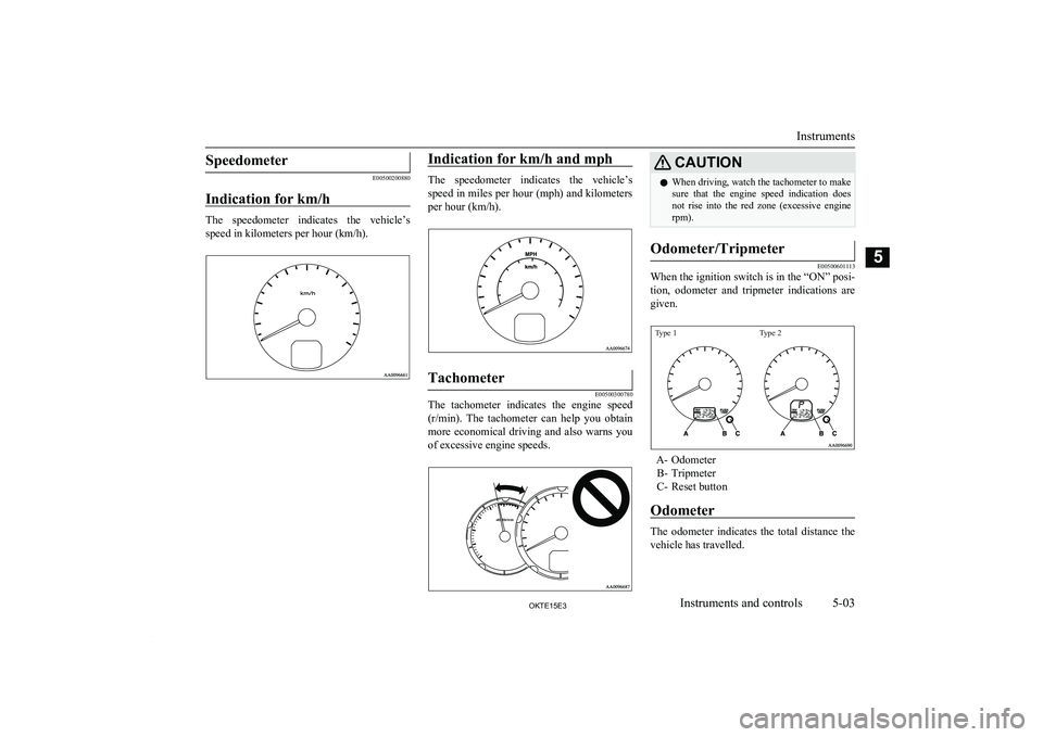
The speedometer indicates the vehicle’s
speed in kilometers per hour (km/h).
Indication for km/h and mph
The speedometer indicates the vehicle’s
speed in miles per hour (mph) and kilometers
per hour (km/h).
Tachometer
E00500300780
The tachometer indicates the engine speed
(r/min). The tachometer can help you obtain
more economical driving and also warns you
of excessive engine speeds.
CAUTIONl When driving, watch the tachometer to make
sure that the engine speed indication does not rise into the red zone (excessive enginerpm).Odometer/Tripmeter
E00500601113
When the ignition switch is in the “ON” posi-
tion, odometer and tripmeter indications are
given.
Type 1Type 2
A- Odometer B- Tripmeter
C- Reset button
Odometer
The odometer indicates the total distance the
vehicle has travelled.
Instruments
5-03OKTE15E3Instruments and controls5
Page 92 of 418
Tripmeter
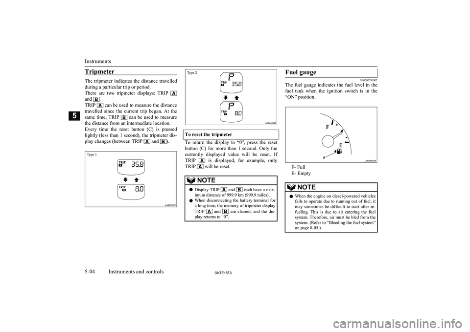
The tripmeter indicates the distance travelled
during a particular trip or period.
There are two tripmeter displays: TRIP
and .
TRIP
can be used to measure the distance
travelled since the current trip began. At the same time, TRIP
can be used to measure
the distance from an intermediate location.
Every time the reset button (C) is pressed
lightly (less than 1 second), the tripmeter dis-
play changes (between TRIP
and ).
Type 1Type 2
To reset the tripmeter
To return the display to “0”, press the reset
button (C) for more than 1 second. Only the currently displayed value will be reset. IfTRIP
is displayed, for example, only
TRIP
will be reset.
NOTEl Display TRIP and
each have a max-
imum distance of 999.9 km (999.9 miles).
l When disconnecting the battery terminal for
a long time, the memory of tripmeter display
TRIP
and are cleared, and the dis-
play returns to “0”.
Fuel gauge
E00500700902
The fuel gauge indicates the fuel level in the
fuel tank when the ignition switch is in the
“ON” position.
F- Full
E- Empty
NOTEl When the engine on diesel-powered vehicles
fails to operate due to running out of fuel, it may sometimes be difficult to start after re-
fueling. This is due to air entering the fuel
system. Therefore, air must be bled from the system. (Refer to “Bleeding the fuel system” on page 8-05.)
Instruments
5-04OKTE15E3Instruments and controls5
Page 93 of 418
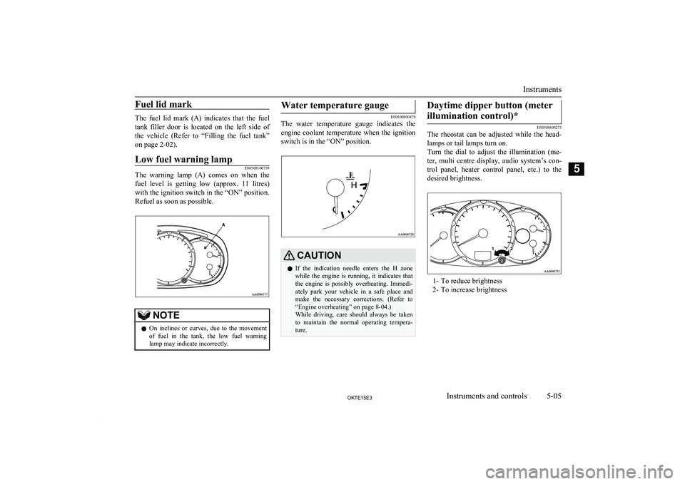
Fuel lid mark
The fuel lid mark (A) indicates that the fueltank filler door is located on the left side of
the vehicle (Refer to “Filling the fuel tank” on page 2-02).
Low fuel warning lampE00508100739
The warning lamp (A) comes on when the fuel level is getting low (approx. 11 litres)
with the ignition switch in the “ON” position.
Refuel as soon as possible.
NOTEl On inclines or curves, due to the movement
of fuel in the tank, the low fuel warning lamp may indicate incorrectly.Water temperature gauge
E00500800479
The water temperature gauge indicates the
engine coolant temperature when the ignition
switch is in the “ON” position.
CAUTIONl If the indication needle enters the H zone
while the engine is running, it indicates that
the engine is possibly overheating. Immedi-
ately park your vehicle in a safe place and make the necessary corrections. (Refer to“Engine overheating” on page 8-04.)
While driving, care should always be taken
to maintain the normal operating tempera- ture.Daytime dipper button (meter
illumination control)*
E00508800273
The rheostat can be adjusted while the head-
lamps or tail lamps turn on.
Turn the dial to adjust the illumination (me- ter, multi centre display, audio system’s con-trol panel, heater control panel, etc.) to thedesired brightness.
1- To reduce brightness
2- To increase brightness
Instruments
5-05OKTE15E3Instruments and controls5
Page 95 of 418
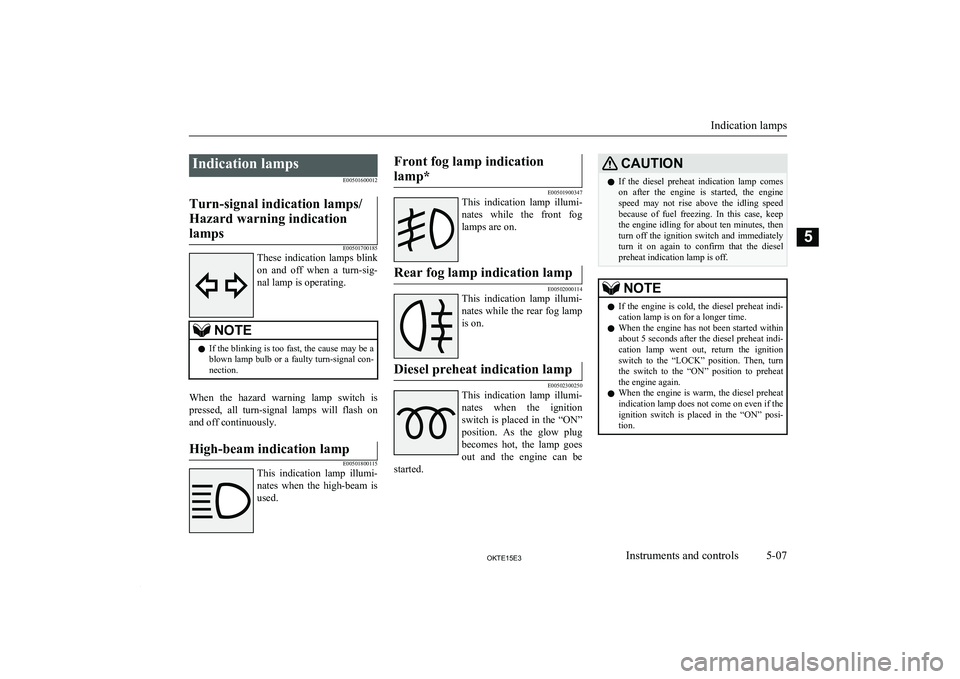
Indication lampsE00501600012Turn-signal indication lamps/
Hazard warning indication lamps
E00501700185
These indication lamps blink
on and off when a turn-sig-
nal lamp is operating.
NOTEl If the blinking is too fast, the cause may be a
blown lamp bulb or a faulty turn-signal con-
nection.
When the hazard warning lamp switch is
pressed, all turn-signal lamps will flash on and off continuously.
High-beam indication lamp
E00501800115
This indication lamp illumi-
nates when the high-beam is used.
Front fog lamp indication
lamp*
E00501900347
This indication lamp illumi-
nates while the front fog
lamps are on.
Rear fog lamp indication lamp
E00502000114
This indication lamp illumi-
nates while the rear fog lamp is on.
Diesel preheat indication lamp
E00502300250
This indication lamp illumi-
nates when the ignition switch is placed in the “ON”
position. As the glow plug becomes hot, the lamp goes
out and the engine can be
started.
CAUTIONl If the diesel preheat indication lamp comes
on after the engine is started, the engine speed may not rise above the idling speedbecause of fuel freezing. In this case, keep
the engine idling for about ten minutes, then turn off the ignition switch and immediately
turn it on again to confirm that the diesel
preheat indication lamp is off.NOTEl If the engine is cold, the diesel preheat indi-
cation lamp is on for a longer time.
l When the engine has not been started within
about 5 seconds after the diesel preheat indi- cation lamp went out, return the ignition
switch to the “LOCK” position. Then, turn
the switch to the “ON” position to preheat the engine again.
l When the engine is warm, the diesel preheat
indication lamp does not come on even if the
ignition switch is placed in the “ON” posi-
tion.
Indication lamps
5-07OKTE15E3Instruments and controls5
Page 96 of 418
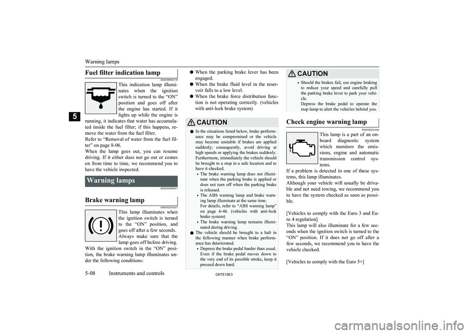
Fuel filter indication lamp
E00509900170
This indication lamp illumi-
nates when the ignition switch is turned to the “ON”
position and goes off after the engine has started. If itlights up while the engine is
running, it indicates that water has accumula- ted inside the fuel filter; if this happens, re-
move the water from the fuel filter.
Refer to “Removal of water from the fuel fil- ter” on page 8-06.When the lamp goes out, you can resume
driving. If it either does not go out or comes on from time to time, we recommend you to
have the vehicle inspected.Warning lamps
E00502400017Brake warning lamp
E00502501637
This lamp illuminates whenthe ignition switch is turnedto the “ON” position, and goes off after a few seconds.
Always make sure that the
lamp goes off before driving.
With the ignition switch in the “ON” posi-
tion, the brake warning lamp illuminates un- der the following conditions:
l When the parking brake lever has been
engaged.
l When the brake fluid level in the reser-
voir falls to a low level.
l When the brake force distribution func-
tion is not operating correctly. (vehicles
with anti-lock brake system)CAUTIONl In the situations listed below, brake perform-
ance may be compromised or the vehicle
may become unstable if brakes are applied
suddenly; consequently, avoid driving at high speeds or applying the brakes suddenly.
Furthermore, immediately the vehicle should be brought to a stop in a safe location and to have it checked.
• The brake warning lamp does not illumi-
nate when the parking brake is applied ordoes not turn off when the parking brake is released.
• The ABS warning lamp and brake warn-
ing lamp illuminate at the same time.
For details, refer to “ABS warning lamp”
on page 6-46. (vehicles with anti-lock
brake system)
• The brake warning lamp remains illumi-
nated during driving.
l The vehicle should be brought to a halt in
the following manner when brake perform-
ance has deteriorated.
• Depress the brake pedal harder than usual.
Even if the brake pedal moves down to
the very end of its possible stroke, keep it
pressed down hard.CAUTION• Should the brakes fail, use engine braking
to reduce your speed and carefully pull the parking brake lever to park your vehi-
cle.
Depress the brake pedal to operate the
stop lamp to alert the vehicles behind you.Check engine warning lamp
E00502601944
This lamp is a part of an on-
board diagnostic system
which monitors the emis-
sions, engine and automatic transmission control sys-tems.
If a problem is detected in one of these sys- tems, this lamp illuminates.
Although your vehicle will usually be driva-
ble and not need towing, we recommend you
to have the system checked as soon as possi-
ble.
[Vehicles to comply with the Euro 3 and Eu-
ro 4 regulation]
This lamp will also illuminate for a few sec- onds when the ignition switch is turned to the “ON” position. If it does not go off after a
few seconds, we recommend you to have the vehicle checked.
[Vehicles to comply with the Euro 5+]
Warning lamps
5-08OKTE15E3Instruments and controls5
Page 97 of 418
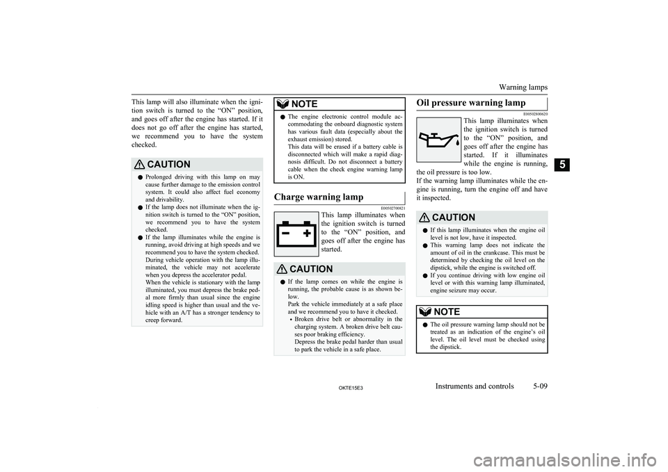
This lamp will also illuminate when the igni-
tion switch is turned to the “ON” position, and goes off after the engine has started. If it
does not go off after the engine has started,
we recommend you to have the system checked.CAUTIONl Prolonged driving with this lamp on may
cause further damage to the emission control
system. It could also affect fuel economy and drivability.
l If the lamp does not illuminate when the ig-
nition switch is turned to the “ON” position, we recommend you to have the system
checked.
l If the lamp illuminates while the engine is
running, avoid driving at high speeds and we recommend you to have the system checked.
During vehicle operation with the lamp illu-
minated, the vehicle may not accelerate
when you depress the accelerator pedal.
When the vehicle is stationary with the lamp illuminated, you must depress the brake ped- al more firmly than usual since the engine
idling speed is higher than usual and the ve- hicle with an A/T has a stronger tendency to
creep forward.NOTEl The engine electronic control module ac-
commodating the onboard diagnostic system has various fault data (especially about the
exhaust emission) stored.
This data will be erased if a battery cable is
disconnected which will make a rapid diag- nosis difficult. Do not disconnect a batterycable when the check engine warning lamp
is ON.Charge warning lamp
E00502700821
This lamp illuminates when
the ignition switch is turnedto the “ON” position, and goes off after the engine has
started.
CAUTIONl If the lamp comes on while the engine is
running, the probable cause is as shown be-low.
Park the vehicle immediately at a safe place
and we recommend you to have it checked.
• Broken drive belt or abnormality in the
charging system. A broken drive belt cau-
ses poor braking efficiency.
Depress the brake pedal harder than usual
to park the vehicle in a safe place.Oil pressure warning lamp
E00502800620
This lamp illuminates when
the ignition switch is turnedto the “ON” position, and goes off after the engine has
started. If it illuminates
while the engine is running,
the oil pressure is too low.
If the warning lamp illuminates while the en- gine is running, turn the engine off and have
it inspected.
CAUTIONl If this lamp illuminates when the engine oil
level is not low, have it inspected.
l This warning lamp does not indicate the
amount of oil in the crankcase. This must be determined by checking the oil level on the
dipstick, while the engine is switched off.
l If you continue driving with low engine oil
level or with this warning lamp illuminated,
engine seizure may occur.NOTEl The oil pressure warning lamp should not be
treated as an indication of the engine’s oil
level. The oil level must be checked using
the dipstick.
Warning lamps
5-09OKTE15E3Instruments and controls5
Page 98 of 418
Door ajar warning lamp
E00503300475
This lamp illuminates when
a door is either open or not
completely closed.
If the vehicle speed reaches approximately 8 km/h
(5 mph) with a door open or
incompletely closed, the warning lamp flash-
es 16 times and a buzzer simultaneously sounds 16 times as a warning.CAUTIONl Before moving your vehicle, check that the
warning lamp is OFF.NOTEl It is possible to change the buzzer setting for
either of the following types of operation.For further information, we recommend you to consult a MITSUBISHI MOTORS Au-
thorized Service Point.NOTE• No buzzer operation (buzzer disabled)
• Continuous buzzer operationCentre information display*
E00517801407WARNINGlWhen operating the system for a pro-
longed period, make sure the vehicle is
parked in a well-ventilated area to avoid
the accumulation of toxic fumes inside and outside of the passenger compart-
ment.CAUTIONl The driver should not operate the display
while the vehicle is in motion.
l When operating the system, stop the vehicle
in a safe area.When the ignition switch is turned to the
“ACC” position, the screen switches on auto- matically.NOTEl Placing a cellular phone in the monitor’s
small storage compartment may weaken the
phone’s reception. This does not indicate a fault with the system.
l Use of wireless devices such as transceivers
or a cellular phone near the monitor may
make the following condition on the display. This does not indicate a fault with the sys-tem.
• The screen goes dark temporarily.
• The compass may not show the correct di-
rection.
l Depending on the angle of view, you may
see reddish horizontal lines on the monitor. The lines are a characteristic of the vacuum fluorescent display (VFD) used in the moni-tor. They do not indicate a fault.
Centre information display*
5-10OKTE15E3Instruments and controls5
Page 102 of 418
Average fuel consumption
E00518200267
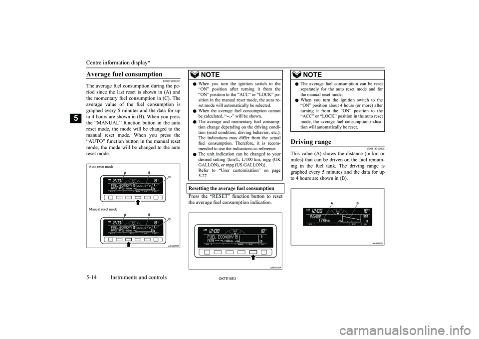
The average fuel consumption during the pe-
riod since the last reset is shown in (A) and
the momentary fuel consumption in (C). The average value of the fuel consumption is
graphed every 5 minutes and the data for up
to 4 hours are shown in (B). When you press
the “MANUAL” function button in the auto reset mode, the mode will be changed to the manual reset mode. When you press the
“AUTO” function button in the manual reset
mode, the mode will be changed to the auto reset mode.
Auto reset modeManual reset mode
NOTEl When you turn the ignition switch to the
“ON” position after turning it from the “ON” position to the “ACC” or “LOCK” po-
sition in the manual reset mode, the auto re- set mode will automatically be selected.
l When the average fuel consumption cannot
be calculated, “--.-” will be shown.
l The average and momentary fuel consump-
tion change depending on the driving condi- tion (road condition, driving behavior, etc.). The indications may differ from the actual
fuel consumption. Therefore, it is recom- mended to use the indications as reference.
l The unit indication can be changed to your
desired setting {km/L, L/100 km, mpg (UK
GALLON), or mpg (US GALLON)}. Refer to “User customization” on page 5-27.
Resetting the average fuel consumption
Press the “RESET” function button to reset
the average fuel consumption indication.
NOTEl The average fuel consumption can be reset
separately for the auto reset mode and forthe manual reset mode.
l When you turn the ignition switch to the
“ON” position about 4 hours (or more) after turning it from the “ON” position to the
“ACC” or “LOCK” position in the auto reset
mode, the average fuel consumption indica-
tion will automatically be reset.Driving range
E00518300095
This value (A) shows the distance (in km or
miles) that can be driven on the fuel remain- ing in the fuel tank. The driving range is
graphed every 5 minutes and the data for up
to 4 hours are shown in (B).
Centre information display*
5-14OKTE15E3Instruments and controls5