engine MITSUBISHI LANCER 2005 Workshop Manual
[x] Cancel search | Manufacturer: MITSUBISHI, Model Year: 2005, Model line: LANCER, Model: MITSUBISHI LANCER 2005Pages: 788, PDF Size: 45.98 MB
Page 176 of 788
TRANSMISSION MOUNTING
POWER PLANT MOUNT32-6
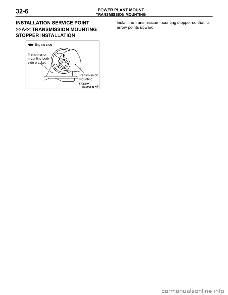
INSTALLATION SERVICE POINT
>>A<< TRANSMISSION MOUNTING
STOPPER INSTALLATIONInstall the transmission mounting stopper so that its
arrow points upward.
AC200645
Engine side
Transmission
mounting body
side bracket
Transmission
mounting
stopper
AB
Page 177 of 788
ENGINE ROLL STOPPER, CENTERMEMBER
POWER PLANT MOUNT32-7
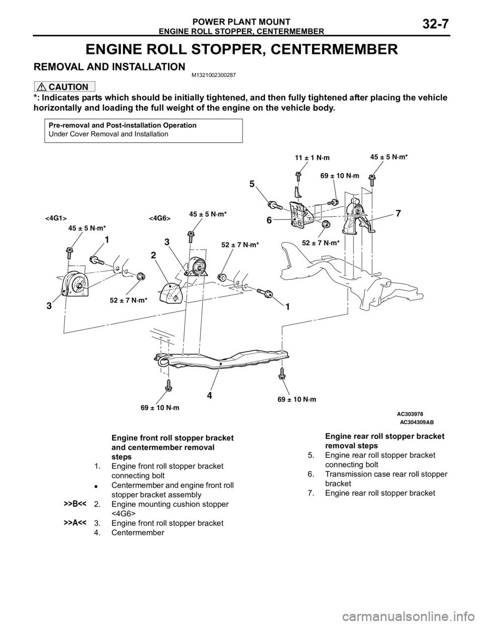
ENGINE ROLL STOPPER, CENTERMEMBER
REMOVAL AND INSTALLATIONM1321002300287
CAUTION
*: Indicates parts which should be initially tightened, and then fully tightened after placing the vehicle
horizontally and loading the full weight of the engine on the vehicle body.
Pre-removal and Post-installation Operation
Under Cover Removal and Installation
AC303978
AC304309
45 ± 5 N·m*45 ± 5 N·m*
<4G1> <4G6>
52 ± 7 N·m*52 ± 7 N·m*
45 ± 5 N·m*
52 ± 7 N·m*
11 ± 1 N·m
69 ± 10 N·m
69 ± 10 N·m69 ± 10 N·m
1
32
1 3
4
5
67
AB
Engine front roll stopper bracket
and centermember removal
steps
1. Engine front roll stopper bracket
connecting bolt
•Centermember and engine front roll
stopper bracket assembly
>>B<<2. Engine mounting cushion stopper
<4G6>
>>A<<3. Engine front roll stopper bracket
4. CentermemberEngine rear roll stopper bracket
removal steps
5. Engine rear roll stopper bracket
connecting bolt
6. Transmission case rear roll stopper
bracket
7. Engine rear roll stopper bracket
Page 178 of 788
CROSSMEMBER
POWER PLANT MOUNT32-8
INSTALLATION SERVICE POINTS
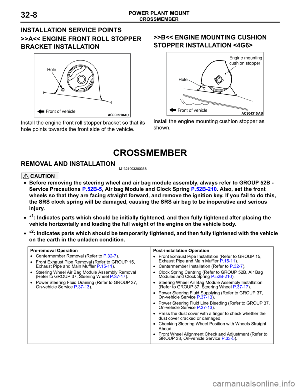
>>A<< ENGINE FRONT ROLL STOPPER
BRACKET INSTALLATION
Install the engine front roll stopper bracket so that its
hole points towards the front side of the vehicle.
>>B<< ENGINE MOUNTING CUSHION
STOPPER INSTALLATION <4G6>
Install the engine mounting cushion stopper as
shown.
CROSSMEMBER
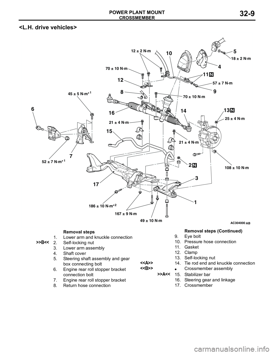
REMOVAL AND INSTALLATIONM1321003200368
CAUTION
•Before removing the steering wheel and air bag module assembly, always refer to GROUP 52B -
Service Precautions P.52B-5, Air bag Module and Clock Spring P.52B-210. Also, set the front
wheels so that they are facing straight forward, and remove the ignition key. If you fail to do this,
the SRS clock spring will be damaged, causing the SRS air bag to be inoperative and serious
injury.
•*
1: Indicates parts which should be initially tightened, and then fully tightened after placing the
vehicle horizontally and loading the full weight of the engine on the vehicle body.
•*
2: Indicates parts which should be temporarily tightened, and then fully tightened with the vehicle
on the earth in the unladen condition.
AC005918Front of vehicleHoleACAC304315ABFront of vehicle
HoleEngine mounting
cushion stopper
Pre-removal Operation
•Centermember Removal (Refer to P.32-7).
•Front Exhaust Pipe Removal (Refer to GROUP 15,
Exhaust Pipe and Main Muffler P.15-11).
•Steering Wheel Air Bag Module Assembly Removal
(Refer to GROUP 37, Steering Wheel P.37-17).
•Power Steering Fluid Draining (Refer to GROUP 37,
On-vehicle Service P.37-13).Post-installation Operation
•Front Exhaust Pipe Installation (Refer to GROUP 15,
Exhaust Pipe and Main Muffler P.15-11).
•Centermember Installation (Refer to P.32-7).
•Clock Spring Centring (Refer to GROUP 52B, Air Bag
Modules and Clock Spring P.52B-210).
•Steering Wheel Air Bag Module Assembly Installation
(Refer to GROUP 37, Steering Wheel P.37-17).
•Power Steering Fluid Supplying (Refer to GROUP 37,
On-vehicle Service P.37-13).
•Power Steering Fluid Line Bleeding (Refer to GROUP 37,
On-vehicle Service P.37-13).
•Press the dust cover with a finger to check whether the
dust cover cracked or damaged.
•Checking Steering Wheel Position with Wheels Straight
Ahead.
•Front Wheel Alignment Check and Adjustment (Refer to
GROUP 33, On-vehicle Service P.33-5).
Page 179 of 788
CROSSMEMBER
POWER PLANT MOUNT32-9
AC304000
108 ± 10 N·m 25 ± 4 N·m 18 ± 2 N·m
70 ± 10 N·m
21 ± 4 N·m 21 ± 4 N·m
186 ± 10 N·m*
167 ± 9 N·m
49 ± 10 N·m 52 ± 7 N·m*45 ± 5 N·m*
70 ± 10 N·m57 ± 7 N·m 12 ± 2 N·m
5
4 10
9 11
8
12
1413 6
716
15
172
3
1
N
N
N
2 11
AB
Removal steps
1. Lower arm and knuckle connection
>>B<<2. Self-locking nut
3. Lower arm assembly
4. Shaft cover
5. Steering shaft assembly and gear
box connecting bolt
6. Engine rear roll stopper bracket
connection bolt
7. Engine rear roll stopper bracket
8. Return hose connection9. Eye bolt
10. Pressure hose connection
11. Gasket
12. Clamp
13. Self-locking nut
<>14. Tie rod end and knuckle connection
<>•Crossmember assembly
>>A<<15. Stabilizer bar
16. Steering gear and linkage
17. CrossmemberRemoval steps (Continued)
Page 180 of 788
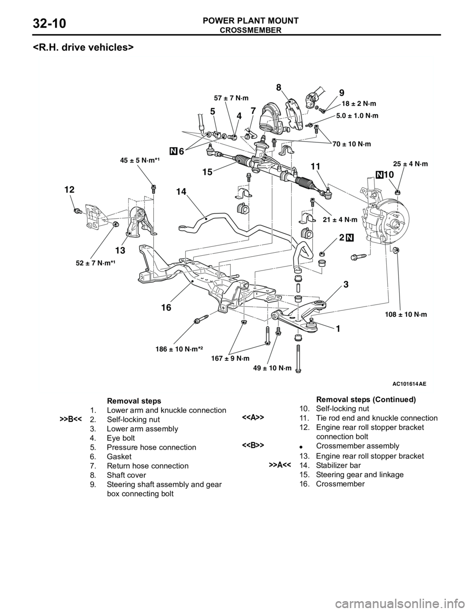
CROSSMEMBER
POWER PLANT MOUNT32-10
AC101614
12
3 4 5
678
9
10 11
12
131415
16
45 ± 5 N·m*¹
52 ± 7 N·m*¹
186 ± 10 N·m*²
167 ± 9 N·m
49 ± 10 N·m108 ± 10 N·m 25 ± 4 N·m
21 ± 4 N·m 70 ± 10 N·m 5.0 ± 1.0 N·m 18 ± 2 N·m 57 ± 7 N·m
N
N
N
AE
Removal steps
1. Lower arm and knuckle connection
>>B<<2. Self-locking nut
3. Lower arm assembly
4. Eye bolt
5. Pressure hose connection
6. Gasket
7. Return hose connection
8. Shaft cover
9. Steering shaft assembly and gear
box connecting bolt10. Self-locking nut<>11. Tie rod end and knuckle connection
12. Engine rear roll stopper bracket
connection bolt
<>•Crossmember assembly
13. Engine rear roll stopper bracket
>>A<<14. Stabilizer bar
15. Steering gear and linkage
16. CrossmemberRemoval steps (Continued)
Page 181 of 788
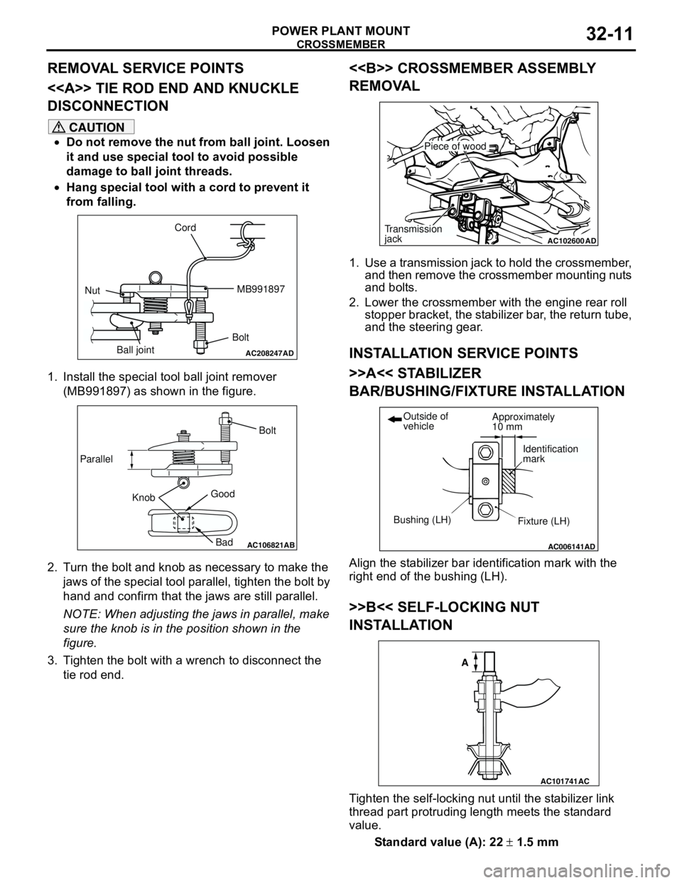
Page 196 of 788
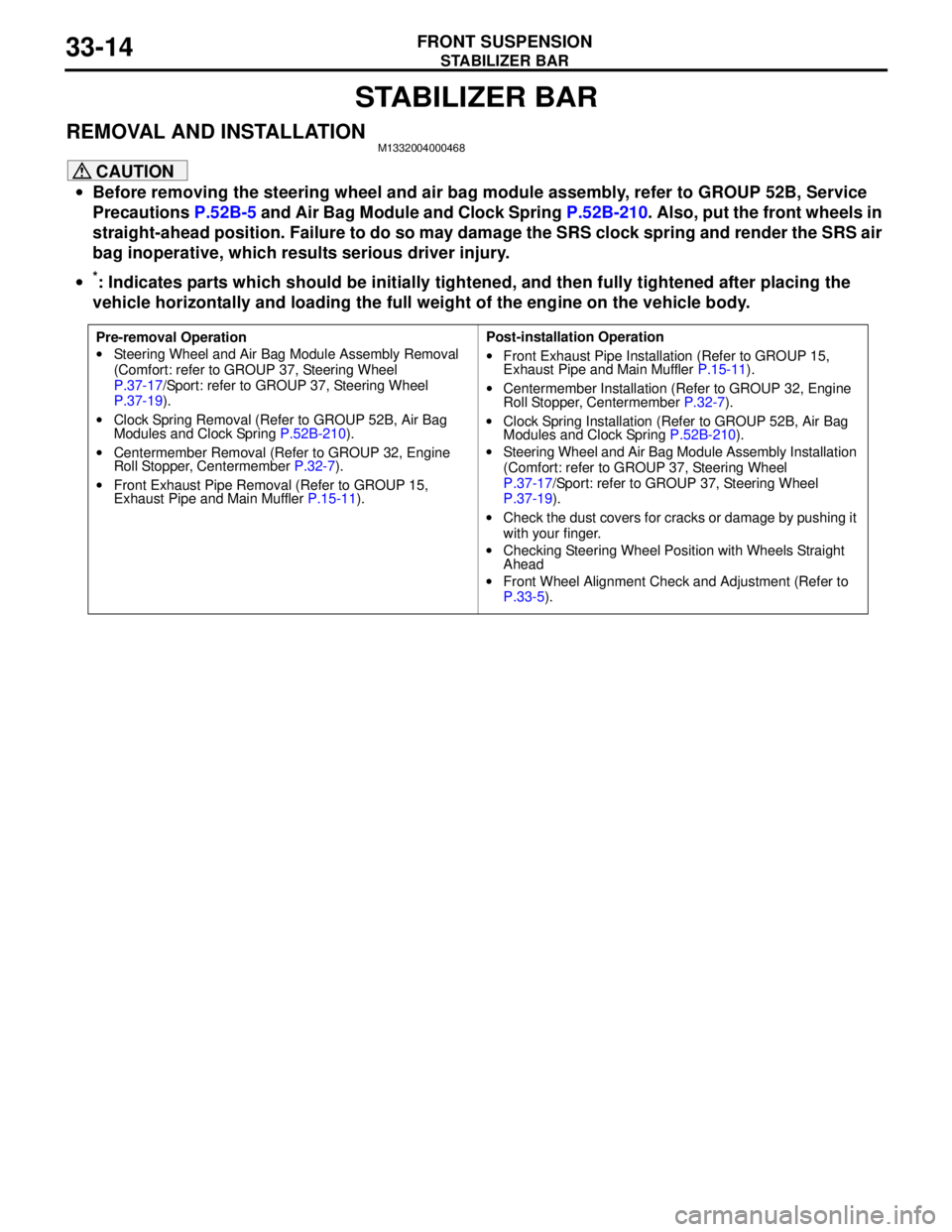
STABILIZER BAR
FRONT SUSPENSION33-14
STABILIZER BAR
REMOVAL AND INSTALLATIONM1332004000468
CAUTION
•Before removing the steering wheel and air bag module assembly, refer to GROUP 52B, Service
Precautions P.52B-5 and Air Bag Module and Clock Spring P.52B-210. Also, put the front wheels in
straight-ahead position. Failure to do so may damage the SRS clock spring and render the SRS air
bag inoperative, which results serious driver injury.
•
*: Indicates parts which should be initially tightened, and then fully tightened after placing the
vehicle horizontally and loading the full weight of the engine on the vehicle body.
Pre-removal Operation
•Steering Wheel and Air Bag Module Assembly Removal
(Comfort: refer to GROUP 37, Steering Wheel
P.37-17/Sport: refer to GROUP 37, Steering Wheel
P.37-19).
•Clock Spring Removal (Refer to GROUP 52B, Air Bag
Modules and Clock Spring P.52B-210).
•Centermember Removal (Refer to GROUP 32, Engine
Roll Stopper, Centermember P.32-7).
•Front Exhaust Pipe Removal (Refer to GROUP 15,
Exhaust Pipe and Main Muffler P.15-11).Post-installation Operation
•Front Exhaust Pipe Installation (Refer to GROUP 15,
Exhaust Pipe and Main Muffler P.15-11).
•Centermember Installation (Refer to GROUP 32, Engine
Roll Stopper, Centermember P.32-7).
•Clock Spring Installation (Refer to GROUP 52B, Air Bag
Modules and Clock Spring P.52B-210).
•Steering Wheel and Air Bag Module Assembly Installation
(Comfort: refer to GROUP 37, Steering Wheel
P.37-17/Sport: refer to GROUP 37, Steering Wheel
P.37-19).
•Check the dust covers for cracks or damage by pushing it
with your finger.
•Checking Steering Wheel Position with Wheels Straight
Ahead
•Front Wheel Alignment Check and Adjustment (Refer to
P.33-5).
Page 197 of 788
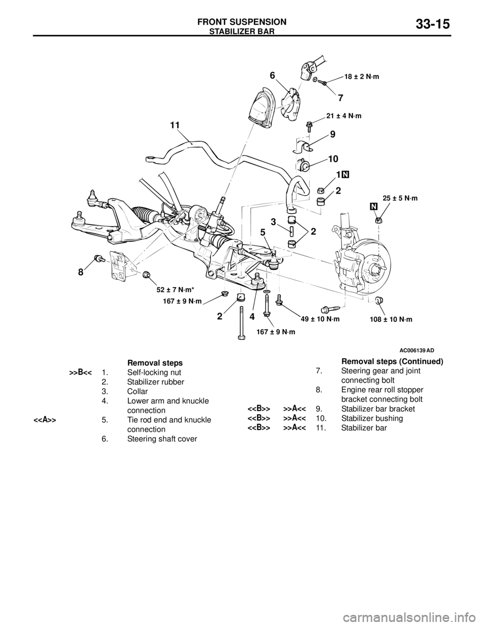
STABILIZER BAR
FRONT SUSPENSION33-15
AC006139
AD
49 ± 10 N·m
108 ± 10 N·m
167 ± 9 N·m 167 ± 9 N·m 52 ± 7 N·m*25 ± 5 N·m 21 ± 4 N·m 18 ± 2 N·m
7 6
9
10
1
2
2 3
5
4 2 11
8
Removal steps
>>B<<1. Self-locking nut
2. Stabilizer rubber
3. Collar
4. Lower arm and knuckle
connection
<>5. Tie rod end and knuckle
connection
6. Steering shaft cover7. Steering gear and joint
connecting bolt
8. Engine rear roll stopper
bracket connecting bolt
<> >>A<<9. Stabilizer bar bracket
<> >>A<<10. Stabilizer bushing
<> >>A<<11. Stabilizer barRemoval steps (Continued)
Page 237 of 788

GENERAL INFORMATION
POWER STEERING37-3
GENERAL INFORMATION
M1372000100337
Power steering has been adopted in all vehicles to
make the steering system easier to handle.
FEATURES
•A 4-spoke steering wheel is used.
•MOMO leather-wrapped 3-spoke steering wheel
is used.
•A steering column has a shock absorbing
mechanism and a tilt steering mechanism.•Integral-type rack and pinion gear with high
rigidity and excellent response is used.
•A vane type pump with a fluid flow rate control
system which change steering effort according to
the engine speed is used.
•The separate plastic resin oil reservoir is used to
reduce weight and to make the fluid level
checking easier.
SPECIFICATIONS
Item Comfort Sport
Steering
wheelType 4-spoke type MOMO leather-wrapped
3-spoke type
Outside diameter mm 380 365
Maximum number of turns 3.19 2.86
3.08
Steering
columnColumn mechanism Shock absorbing mechanism and Tilt steering mechanism
Power steering type Integral type
Oil pump Type Vane pump
Basic discharge amount cm
3/rev.7.2 <1300, 1600>
8.1 <2000>7.2 <1300, 1600>
8.1 <2000>
Relief pressure MPa 8.8 8.8
Reservoir type Separate type (plastic)
Pressure switch Equipped
Steering
gearType Rack and pinion
Stroke ratio (Rack stroke/Steering
wheel maximum turning radius)45.74 45.74
Rack stroke mm 146 131
141
Page 240 of 788

SERVICE SPECIFICATIONS
POWER STEERING37-6
SERVICE SPECIFICATIONS
M1372000300386
Item Standard value Limit
Steering wheel free
play mmWith engine running
−30
With engine stopped 10 or less
−
Steering angle Inner wheel Comfort 39°30' ± 1°30'
−
Sport (L.H. drive vehicles) 33°40' +1°00'/-2°00'
−
Sport (R.H. drive vehicles) 37°00' +1°00'/-2°00'
−
Outer wheel
(reference)Comfort 32°30'
−
Sport (L.H. drive vehicles) 28°46'
−
Sport (R.H. drive vehicles) 30°00'
−
Toe-in At the centre of tyre tread mm 1 ± 2
−
Toe-angle (per wheel) 0°03' ± 06'
−
Tie rod end ball joint turning torque N⋅m0.5 − 2.5
−
Tie rod swing resistance N [Tie rod swing torque N⋅m] 8 − 27 [1.5 − 4.9]
−
Stationary steering effort N [Fluctuation allowance N] 29 or less [5.9 or less]
−
Oil pump pressure
MPa (750 ± 100 r/min.)Oil pump relief pressure 8.8 − 9.5
−
Pressure under no-load conditions 0.2 − 0.7
−
Steering gear retention hydraulic pressure 8.8 − 9.5
−
Oil pressure switch operating pressure
MPaOFF → ON 1.5 − 2.0
−
ON → OFF 0.7 − 2.0
−
Steering gear total pinion torque N⋅m
[Change in torque N⋅m]1300, 1600 (Comfort) 0.8 − 2.1 [0.6 or less]
−
1600 (Sport), 2000 0.7 − 2.1 [0.6 or less]
−
Opening dimension of special tool boot band crimping tool (MB991561)
mm2.9
−
Band crimped width mm 2.4 − 2.8
−