torque MITSUBISHI LANCER 2005 Workshop Manual
[x] Cancel search | Manufacturer: MITSUBISHI, Model Year: 2005, Model line: LANCER, Model: MITSUBISHI LANCER 2005Pages: 788, PDF Size: 45.98 MB
Page 10 of 788
ON-VEHICLE SERVICE
ENGINE LUBRICATION12-4
ON-VEHICLE SERVICE
ENGINE OIL CHECKM1121000900342
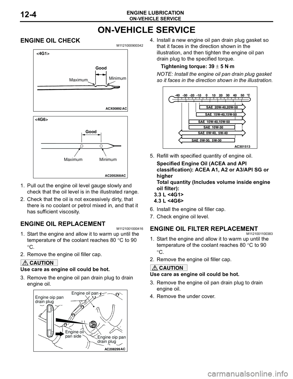
1. Pull out the engine oil level gauge slowly and
check that the oil level is in the illustrated range.
2. Check that the oil is not excessively dirty, that
there is no coolant or petrol mixed in, and that it
has sufficient viscosity.
ENGINE OIL REPLACEMENTM1121001000416
1. Start the engine and allow it to warm up until the
temperature of the coolant reaches 80 °C to 90
°C.
2. Remove the engine oil filler cap.
CAUTION
Use care as engine oil could be hot.
3. Remove the engine oil pan drain plug to drain
engine oil.4. Install a new engine oil pan drain plug gasket so
that it faces in the direction shown in the
illustration, and then tighten the engine oil pan
drain plug to the specified torque.
Tightening torque: 39 ± 5 N⋅m
NOTE: Install the engine oil pan drain plug gasket
so it faces in the direction shown in the illustration.
5. Refill with specified quantity of engine oil.
Specified Engine Oil (ACEA and API
classification): ACEA A1, A2 or A3/API SG or
higher
Total quantity (Includes volume inside engine
oil filter):
3.3 L <4G1>
4.3 L <4G6>
6. Install the engine oil filler cap.
7. Check engine oil level.
ENGINE OIL FILTER REPLACEMENTM1121001100383
1. Start the engine and allow it to warm up until the
temperature of the coolant reaches 80 °C to 90
°C.
2. Remove the engine oil filler cap.
CAUTION
Use care as engine oil could be hot.
3. Remove the engine oil pan drain plug to drain
engine oil.
4. Remove the under cover.
ACX00892 AC
Good
MaximumMinimum
<4G1>
AC205268
Maximum MinimumGood
AC
<4G6>
AC208299
Engine oil pan
AC
Engine oip pan
drain plug
Engine oip pan
drain plug
Engine oil
pan side
AC301513
Page 11 of 788
ON-VEHICLE SERVICE
ENGINE LUBRICATION12-5
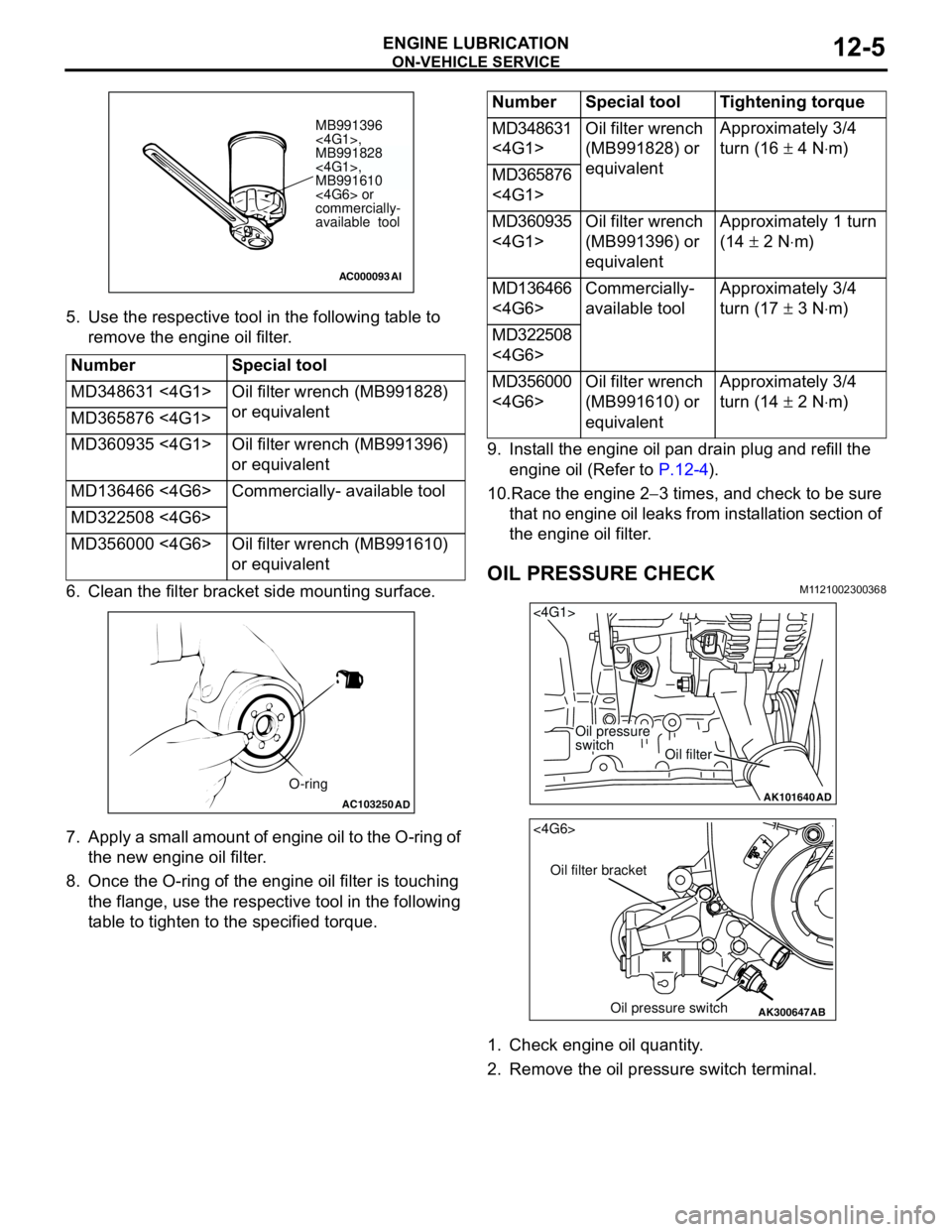
5. Use the respective tool in the following table to
remove the engine oil filter.
6. Clean the filter bracket side mounting surface.
7. Apply a small amount of engine oil to the O-ring of
the new engine oil filter.
8. Once the O-ring of the engine oil filter is touching
the flange, use the respective tool in the following
table to tighten to the specified torque.9. Install the engine oil pan drain plug and refill the
engine oil (Refer to P.12-4).
10.Race the engine 2−3 times, and check to be sure
that no engine oil leaks from installation section of
the engine oil filter.
OIL PRESSURE CHECKM1121002300368
1. Check engine oil quantity.
2. Remove the oil pressure switch terminal. Number Special tool
MD348631 <4G1> Oil filter wrench (MB991828)
or equivalent
MD365876 <4G1>
MD360935 <4G1> Oil filter wrench (MB991396)
or equivalent
MD136466 <4G6> Commercially- available tool
MD322508 <4G6>
MD356000 <4G6> Oil filter wrench (MB991610)
or equivalent
AC000093
MB991396
<4G1>,
MB991828
<4G1>,
MB991610
<4G6> or
commercially-
available tool
AI
AC103250AD
O-ring
Number Special tool Tightening torque
MD348631
<4G1>Oil filter wrench
(MB991828) or
equivalentApproximately 3/4
turn (16 ± 4 N⋅m)
MD365876
<4G1>
MD360935
<4G1>Oil filter wrench
(MB991396) or
equivalentApproximately 1 turn
(14 ± 2 N⋅m)
MD136466
<4G6>Commercially-
available toolApproximately 3/4
turn (17 ± 3 N⋅m)
MD322508
<4G6>
MD356000
<4G6>Oil filter wrench
(MB991610) or
equivalentApproximately 3/4
turn (14 ± 2 N⋅m)
AK101640
<4G1>
Oil pressure
switch
Oil filter
AD
AK300647
AB
<4G6>
Oil filter bracket
Oil pressure switch
Page 12 of 788
ON-VEHICLE SERVICE
ENGINE LUBRICATION12-6
CAUTION
Since sealant is applied to the thread of oil
pressure switch, take care not to damage the oil
pressure switch when removing it.
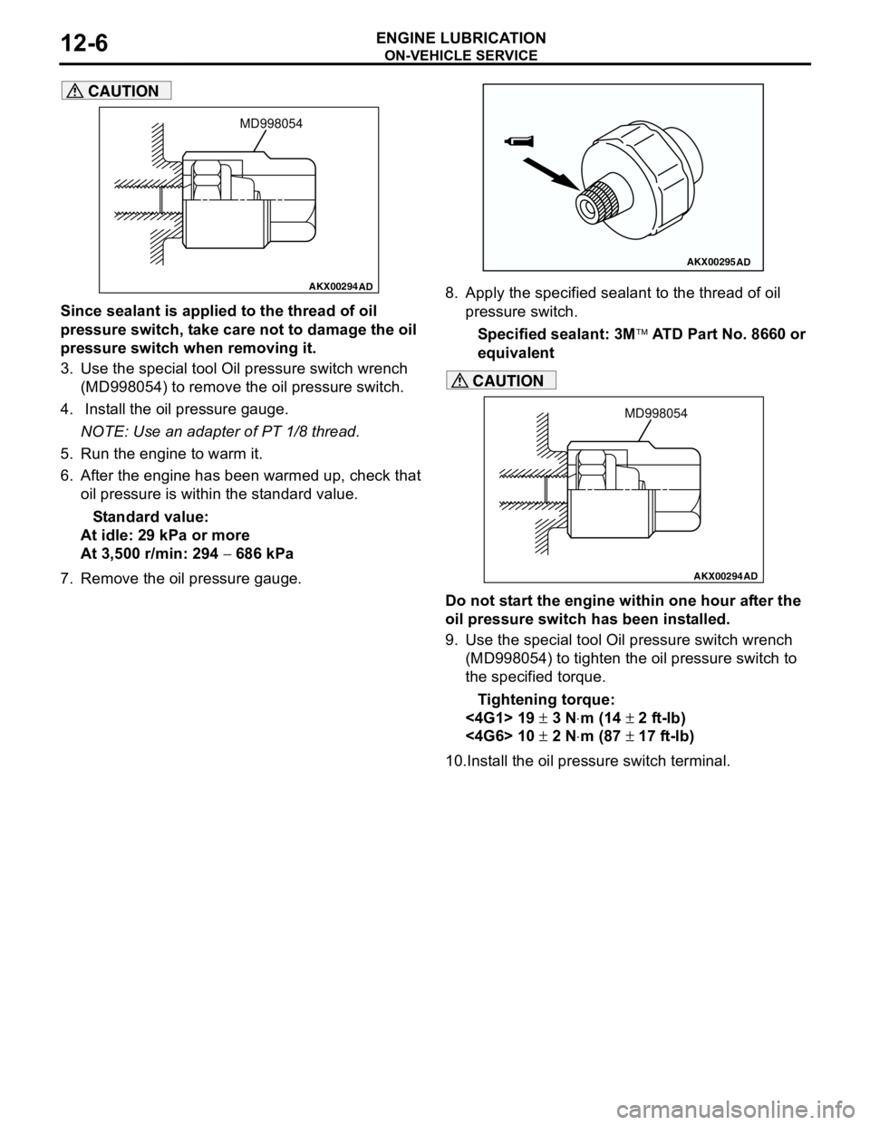
3. Use the special tool Oil pressure switch wrench
(MD998054) to remove the oil pressure switch.
4. Install the oil pressure gauge.
NOTE: Use an adapter of PT 1/8 thread.
5. Run the engine to warm it.
6. After the engine has been warmed up, check that
oil pressure is within the standard value.
Standard value:
At idle: 29 kPa or more
At 3,500 r/min: 294 − 686 kPa
7. Remove the oil pressure gauge.8. Apply the specified sealant to the thread of oil
pressure switch.
Specified sealant: 3M ATD Part No. 8660 or
equivalent
CAUTION
Do not start the engine within one hour after the
oil pressure switch has been installed.
9. Use the special tool Oil pressure switch wrench
(MD998054) to tighten the oil pressure switch to
the specified torque.
Tightening torque:
<4G1> 19 ± 3 N⋅m (14 ± 2 ft-lb)
<4G6> 10 ± 2 N⋅m (87 ± 17 ft-lb)
10.Install the oil pressure switch terminal.
AKX00294
MD998054
AD
AKX00295AD
AKX00294
MD998054
AD
Page 37 of 788
ON-VEHICLE SERVICE
ENGINE COOLING14-23
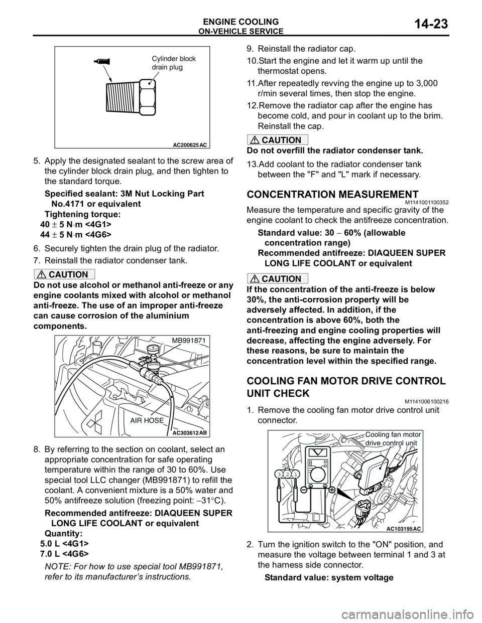
5. Apply the designated sealant to the screw area of
the cylinder block drain plug, and then tighten to
the standard torque.
Specified sealant: 3M Nut Locking Part
No.4171 or equivalent
Tightening torque:
40 ± 5 N⋅m <4G1>
44 ± 5 N⋅m <4G6>
6. Securely tighten the drain plug of the radiator.
7. Reinstall the radiator condenser tank.
CAUTION
Do not use alcohol or methanol anti-freeze or any
engine coolants mixed with alcohol or methanol
anti-freeze. The use of an improper anti-freeze
can cause corrosion of the aluminium
components.
8. By referring to the section on coolant, select an
appropriate concentration for safe operating
temperature within the range of 30 to 60%. Use
special tool LLC changer (MB991871) to refill the
coolant. A convenient mixture is a 50% water and
50% antifreeze solution (freezing point: −31°C).
Recommended antifreeze: DIAQUEEN SUPER
LONG LIFE COOLANT or equivalent
Quantity:
5.0 L <4G1>
7.0 L <4G6>
NOTE: For how to use special tool MB991871,
refer to its manufacturer’s instructions.9. Reinstall the radiator cap.
10.Start the engine and let it warm up until the
thermostat opens.
11.After repeatedly revving the engine up to 3,000
r/min several times, then stop the engine.
12.Remove the radiator cap after the engine has
become cold, and pour in coolant up to the brim.
Reinstall the cap.
CAUTION
Do not overfill the radiator condenser tank.
13.Add coolant to the radiator condenser tank
between the "F" and "L" mark if necessary.
CONCENTRATION MEASUREMENTM1141001100352
Measure the temperature and specific gravity of the
engine coolant to check the antifreeze concentration.
Standard value: 30 − 60% (allowable
concentration range)
Recommended antifreeze: DIAQUEEN SUPER
LONG LIFE COOLANT or equivalent
CAUTION
If the concentration of the anti-freeze is below
30%, the anti-corrosion property will be
adversely affected. In addition, if the
concentration is above 60%, both the
anti-freezing and engine cooling properties will
decrease, affecting the engine adversely. For
these reasons, be sure to maintain the
concentration level within the specified range.
COOLING FAN MOTOR DRIVE CONTROL
UNIT CHECK
M1141006100216
1. Remove the cooling fan motor drive control unit
connector.
2. Turn the ignition switch to the "ON" position, and
measure the voltage between terminal 1 and 3 at
the harness side connector.
Standard value: system voltage
AC200625
Cylinder block
drain plug
AC
AC303612AB
MB991871
AIR HOSE
AC103195
Y1716AU
1 23
AC
Cooling fan motor
drive control unit
Page 94 of 788
IGNITION SYSTEM
ENGINE ELECTRICAL16-30
IGNITION SYSTEM
GENERAL INFORMATIONM1163000100294
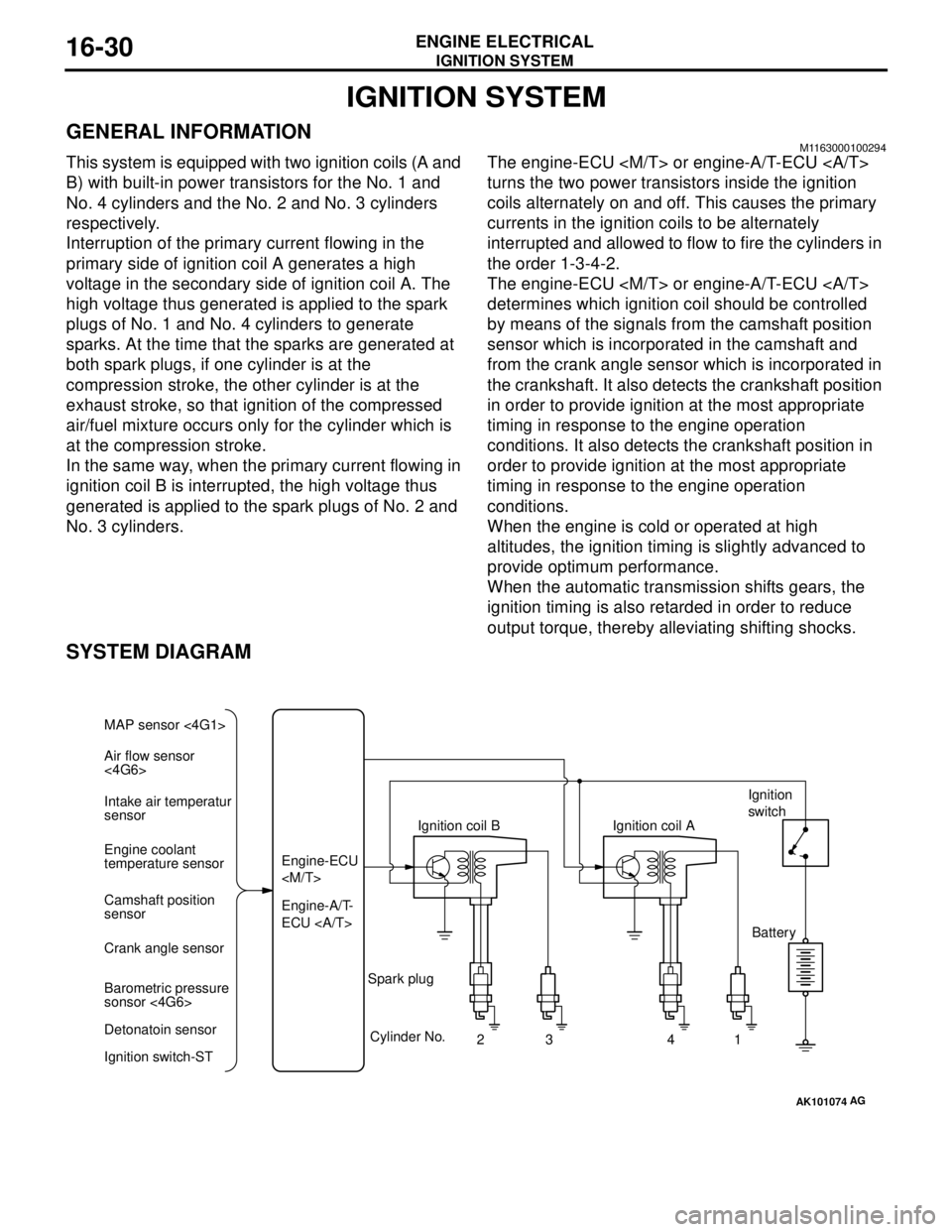
This system is equipped with two ignition coils (A and
B) with built-in power transistors for the No. 1 and
No. 4 cylinders and the No. 2 and No. 3 cylinders
respectively.
Interruption of the primary current flowing in the
primary side of ignition coil A generates a high
voltage in the secondary side of ignition coil A. The
high voltage thus generated is applied to the spark
plugs of No. 1 and No. 4 cylinders to generate
sparks. At the time that the sparks are generated at
both spark plugs, if one cylinder is at the
compression stroke, the other cylinder is at the
exhaust stroke, so that ignition of the compressed
air/fuel mixture occurs only for the cylinder which is
at the compression stroke.
In the same way, when the primary current flowing in
ignition coil B is interrupted, the high voltage thus
generated is applied to the spark plugs of No. 2 and
No. 3 cylinders.The engine-ECU
turns the two power transistors inside the ignition
coils alternately on and off. This causes the primary
currents in the ignition coils to be alternately
interrupted and allowed to flow to fire the cylinders in
the order 1-3-4-2.
The engine-ECU
determines which ignition coil should be controlled
by means of the signals from the camshaft position
sensor which is incorporated in the camshaft and
from the crank angle sensor which is incorporated in
the crankshaft. It also detects the crankshaft position
in order to provide ignition at the most appropriate
timing in response to the engine operation
conditions. It also detects the crankshaft position in
order to provide ignition at the most appropriate
timing in response to the engine operation
conditions.
When the engine is cold or operated at high
altitudes, the ignition timing is slightly advanced to
provide optimum performance.
When the automatic transmission shifts gears, the
ignition timing is also retarded in order to reduce
output torque, thereby alleviating shifting shocks.
SYSTEM DIAGRAM
AK101074
Air flow sensor
<4G6> MAP sensor <4G1>
Intake air temperatur
sensor
Engine coolant
temperature sensor
Camshaft position
sensor
Crank angle sensor
Barometric pressure
sonsor <4G6>
Detonatoin sensor
Ignition switch-STEngine-A/T-
ECU Engine-ECU
Cylinder No.
23 4
AG
1 Spark plugIgnition coil AIgnition
switch
Battery
Page 108 of 788
IGNITION SYSTEM
ENGINE ELECTRICAL16-44
REMOVAL SERVICE POINT
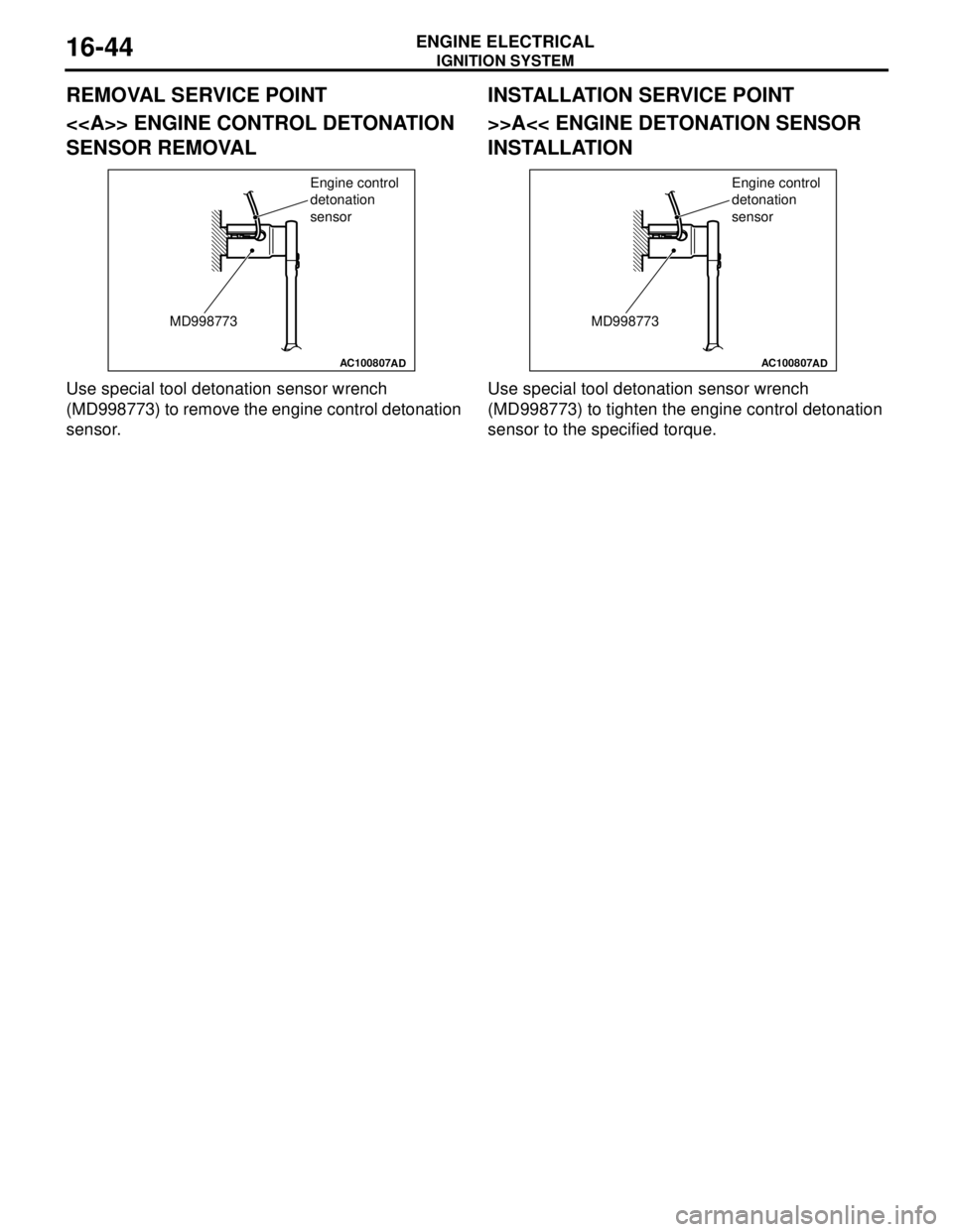
<> ENGINE CONTROL DETONATION
SENSOR REMOVAL
Use special tool detonation sensor wrench
(MD998773) to remove the engine control detonation
sensor.
INSTALLATION SERVICE POINT
>>A<< ENGINE DETONATION SENSOR
INSTALLATION
Use special tool detonation sensor wrench
(MD998773) to tighten the engine control detonation
sensor to the specified torque.
AC100807
MD998773Engine control
detonation
sensor
ADAC100807
MD998773Engine control
detonation
sensor
AD
Page 124 of 788
EMISSION CONTROL
ENGINE AND EMISSION CONTROL17-16
5. Replace the gasket, and tighten to the specified
torque.
Tightening torque:
<4G1> 21 ± 4 N⋅m
<4G6> 20 ± 2 N⋅m
EGR PORT VACUUM CHECK <4G1>M1173002900167
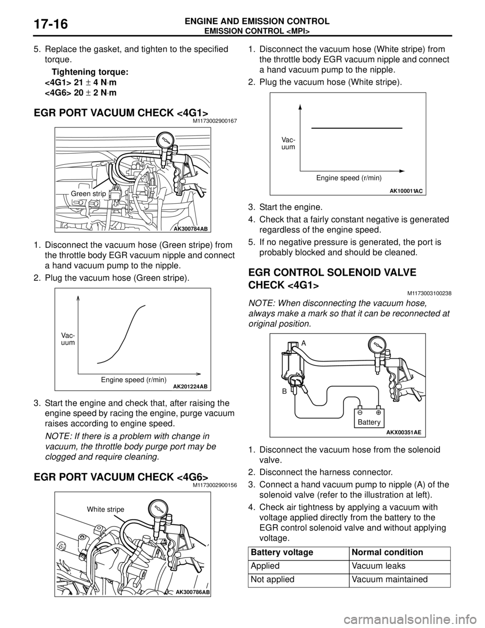
1. Disconnect the vacuum hose (Green stripe) from
the throttle body EGR vacuum nipple and connect
a hand vacuum pump to the nipple.
2. Plug the vacuum hose (Green stripe).
3. Start the engine and check that, after raising the
engine speed by racing the engine, purge vacuum
raises according to engine speed.
NOTE: If there is a problem with change in
vacuum, the throttle body purge port may be
clogged and require cleaning.
EGR PORT VACUUM CHECK <4G6>M1173002900156
1. Disconnect the vacuum hose (White stripe) from
the throttle body EGR vacuum nipple and connect
a hand vacuum pump to the nipple.
2. Plug the vacuum hose (White stripe).
3. Start the engine.
4. Check that a fairly constant negative is generated
regardless of the engine speed.
5. If no negative pressure is generated, the port is
probably blocked and should be cleaned.
EGR CONTROL SOLENOID VALVE
CHECK <4G1>
M1173003100238
NOTE: When disconnecting the vacuum hose,
always make a mark so that it can be reconnected at
original position.
1. Disconnect the vacuum hose from the solenoid
valve.
2. Disconnect the harness connector.
3. Connect a hand vacuum pump to nipple (A) of the
solenoid valve (refer to the illustration at left).
4. Check air tightness by applying a vacuum with
voltage applied directly from the battery to the
EGR control solenoid valve and without applying
voltage.
AK300784AB
Green strip
AK201224AB
Vac-
uum
Engine speed (r/min)
AK300786AB
White stripe
Battery voltage Normal condition
Applied Vacuum leaks
Not applied Vacuum maintained
AK100011AC
Vac-
uum
Engine speed (r/min)
AKX00351
A
B
AE
Battery
Page 135 of 788

SERVICE SPECIFICATIONS
FRONT AXLE26-3
SERVICE SPECIFICATIONS
M1261000300396
LUBRICANTS
M1261000400382
Item Standard value Limit
Wheel bearing axial play mm
−0.05
Hub starting torque N⋅m
−1.8
Protruding length of stabilizer bar mounting bolt mm 22 ± 1.5
−
Setting of TJ boot length mm 1.3L-RH, 1.6L-A/T-RH 85 ± 3
−
1.3L-LH, 1.6L-M/T,
1.6L-A/T-LH, 2.0L90 ± 3
−
Opening dimension of the
special tool (MB991561) mmWhen the BJ boot band
(small) is crimped2.9
−
When the BJ boot band
(large) is crimped2.9
−
Crimped width of the BJ boot band mm 2.4 − 2.8
−
Item Specified lubricant Quantity
TJ boot grease Repair kit grease 1.3L-LH, 1.6L-LH, 2.0L-LH 120 ± 10 g
1.3L-RH, 1.6L-A/T-RH 110 ± 10 g
1.6L-M/T-RH 120 ± 10 g
2.0L-RH 105 ± 10 g
BJ boot grease Repair kit grease 95 ± 10 g
Page 136 of 788
SPECIAL TOOLS
FRONT AXLE26-4
SPECIAL TOOLS
M1261000600375
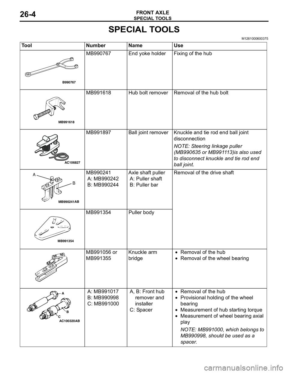
Tool Number Name Use
MB990767 End yoke holder Fixing of the hub
MB991618 Hub bolt remover Removal of the hub bolt
MB991897 Ball joint remover Knuckle and tie rod end ball joint
disconnection
NOTE: Steering linkage puller
(MB990635 or MB991113)is also used
to disconnect knuckle and tie rod end
ball joint.
MB990241
A: MB990242
B: MB990244Axle shaft puller
A: Puller shaft
B: Puller barRemoval of the drive shaft
MB991354 Puller body
MB991056 or
MB991355Knuckle arm
bridge•Removal of the hub
•Removal of the wheel bearing
A: MB991017
B: MB990998
C: MB991000A, B: Front hub
remover and
installer
C: Spacer•Removal of the hub
•Provisional holding of the wheel
bearing
•Measurement of hub starting torque
•Measurement of wheel bearing axial
play
NOTE: MB991000, which belongs to
MB990998, should be used as a
spacer.
B990767
MB991618
AC106827
MB990241AB
A
B
MB991354
AC100320 ABA
B
C
Page 137 of 788
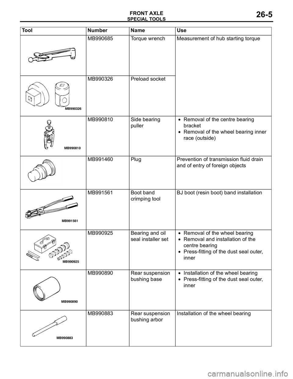
SPECIAL TOOLS
FRONT AXLE26-5
MB990685 Torque wrench Measurement of hub starting torque
MB990326 Preload socket
MB990810 Side bearing
puller•Removal of the centre bearing
bracket
•Removal of the wheel bearing inner
race (outside)
MB991460 Plug Prevention of transmission fluid drain
and of entry of foreign objects
MB991561 Boot band
crimping toolBJ boot (resin boot) band installation
MB990925 Bearing and oil
seal installer set•Removal of the wheel bearing
•Removal and installation of the
centre bearing
•Press-fitting of the dust seal outer,
inner
MB990890 Rear suspension
bushing base•Installation of the wheel bearing
•Press-fitting of the dust seal outer,
inner
MB990883 Rear suspension
bushing arborInstallation of the wheel bearing Tool Number Name Use
MB990326
MB990810
MB991561
MB990925
MB990890
MB990883