MITSUBISHI LANCER 2005 Workshop Manual
LANCER 2005
MITSUBISHI
MITSUBISHI
https://www.carmanualsonline.info/img/19/57321/w960_57321-0.png
MITSUBISHI LANCER 2005 Workshop Manual
Page 585 of 788
DUCTS
HEATER, AIR CONDITIONER AND VENTILATION55-101
DUCTS
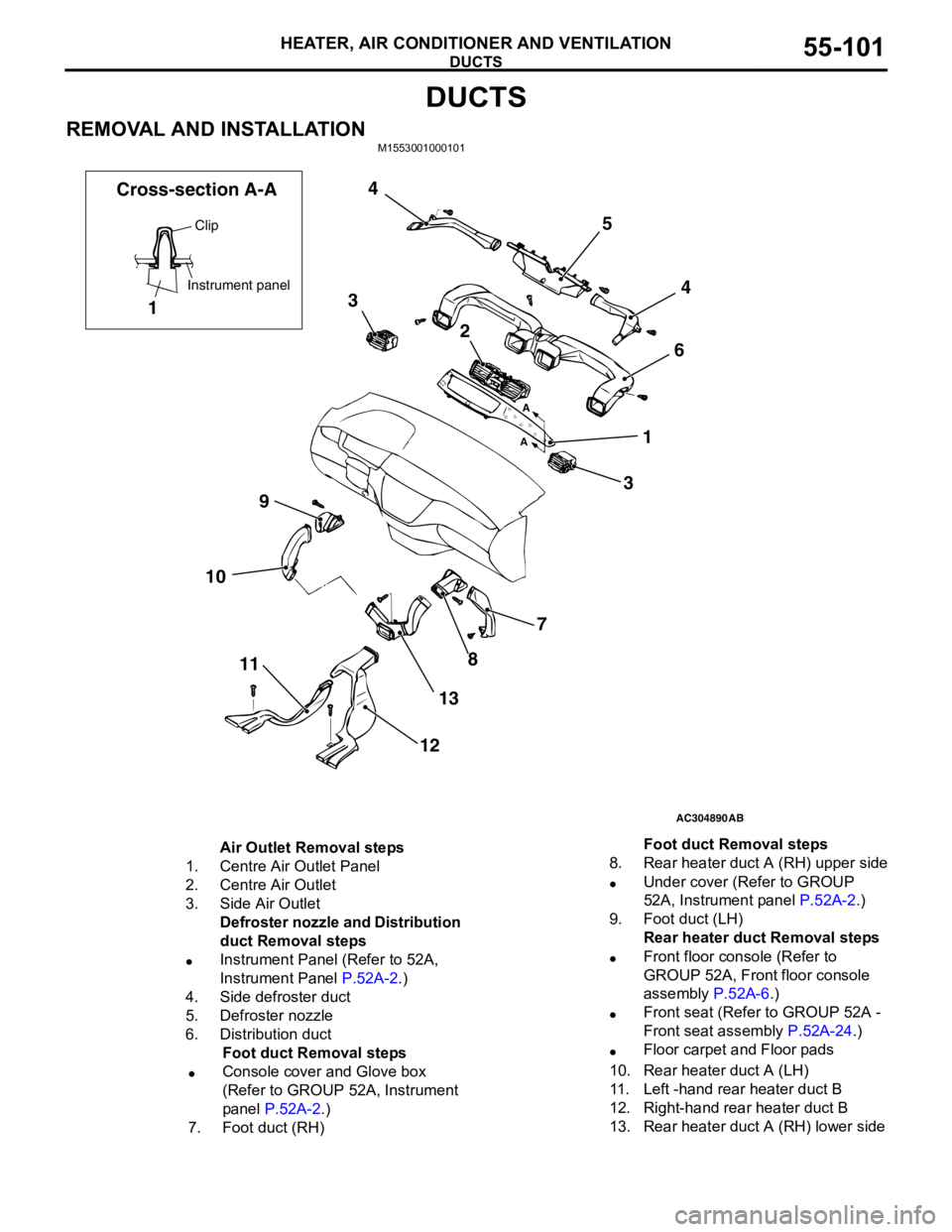
REMOVAL AND INSTALLATIONM1553001000101
AC304890
7
8
13
12 11 109364 5 4
3
2
1
AB A
A
Clip
Instrument panel
1 Cross-section A-A
Air Outlet Removal steps
1. Centre Air Outlet Panel
2. Centre Air Outlet
3. Side Air Outlet
Defroster nozzle and Distribution
duct Removal steps
•Instrument Panel (Refer to 52A,
Instrument Panel P.52A-2.)
4. Side defroster duct
5. Defroster nozzle
6. Distribution duct
Foot duct Removal steps
•Console cover and Glove box
(Refer to GROUP 52A, Instrument
panel P.52A-2.)
7. Foot duct (RH)8. Rear heater duct A (RH) upper side
•Under cover (Refer to GROUP
52A, Instrument panel P.52A-2.)
9. Foot duct (LH)
Rear heater duct Removal steps
•Front floor console (Refer to
GROUP 52A, Front floor console
assembly P.52A-6.)
•Front seat (Refer to GROUP 52A -
Front seat assembly P.52A-24.)
•Floor carpet and Floor pads
10. Rear heater duct A (LH)
11. Left -hand rear heater duct B
12. Right-hand rear heater duct B
13. Rear heater duct A (RH) lower sideFoot duct Removal steps
Page 586 of 788
VENTILATORS
HEATER, AIR CONDITIONER AND VENTILATION55-102
VENTILATORS
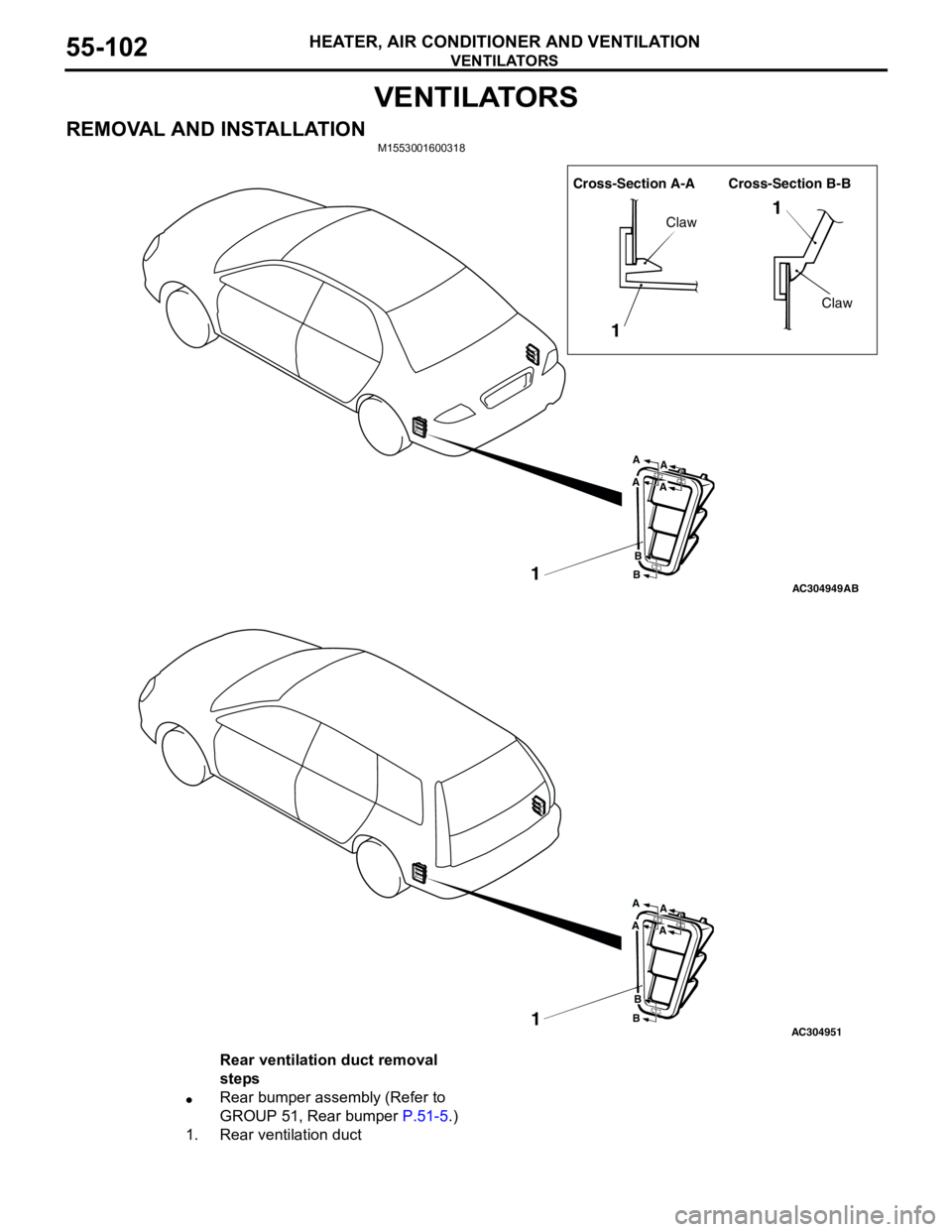
REMOVAL AND INSTALLATIONM1553001600318
AC304949
Cross-Section A-A Cross-Section B-B
1
11
Claw
Claw
A
A
B
B
A
A
AB
AC3049511
A
A
B
B
A
A
Rear ventilation duct removal
steps
•Rear bumper assembly (Refer to
GROUP 51, Rear bumper P.51-5.)
1. Rear ventilation duct
Page 589 of 788
ECU
COMPONENT LOCATIONS70-3
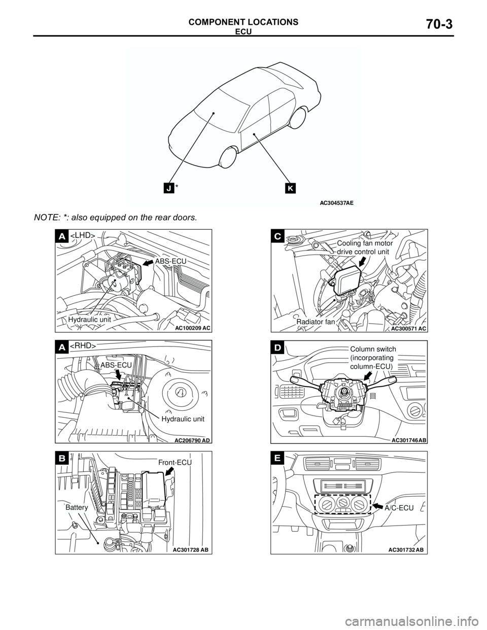
NOTE: *: also equipped on the rear doors.
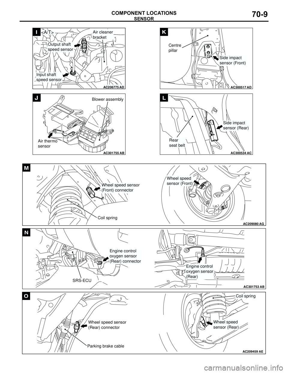
AC304537
JK*
AE
AC100209AC
A
ABS-ECU
Hydraulic unit
AC206790
A
AD
ABS-ECU
Hydraulic unit
AC301728AB
BFront-ECU
Battery
AC300571
C
ACRadiator fan
Cooling fan motor
drive control unit
AC301746
DColumn switch
(incorporating
column-ECU)
AB
AC301732AB
E
A/C-ECU
Page 591 of 788
RELAY
COMPONENT LOCATIONS70-5
RELAY
M1701000400369
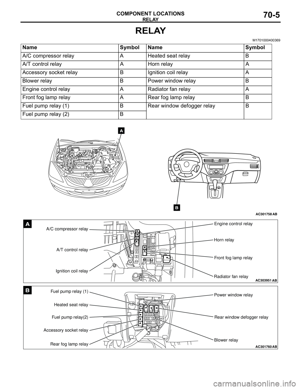
Name Symbol Name Symbol
A/C compressor relay A Heated seat relay B
A/T control relay A Horn relay A
Accessory socket relay B Ignition coil relay A
Blower relay B Power window relay B
Engine control relay A Radiator fan relay A
Front fog lamp relay A Rear fog lamp relay B
Fuel pump relay (1) B Rear window defogger relay B
Fuel pump relay (2) B
AC301758AB
A
B
AC303951AB
A/C compressor relayEngine control relay
Horn relay
Front fog lamp relay
Radiator fan relay A/T control relay
Ignition coil relayA
AC301760
Fuel pump relay (1)
Power window relay
Rear window defogger relay
Blower relay Heated seat relay
Fuel pump relay(2)
Accessory socket relay
Rear fog lamp relayAB
B
Page 592 of 788
Page 595 of 788
Page 603 of 788
EARTH
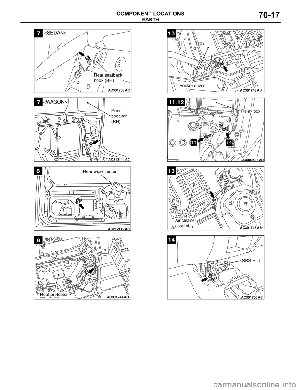
COMPONENT LOCATIONS70-17
AC301208
7
AC
Rear seatback
hook (RH)
AC212111
7
AC
Rear
speaker
(RH)
AC212112AC
8Rear wiper motor
AC301744AB
9
Heat protector
AC301743AB
10
Rocker cover
AC300437
11
12
,
1112
AD
Relay box
AC301745
13
AB
Air cleaner
assembly
AC301750AB
14
SRS-ECU
Page 604 of 788
INSPECTION CONNECTOR AND SPARE CONNECTOR
COMPONENT LOCATIONS70-18
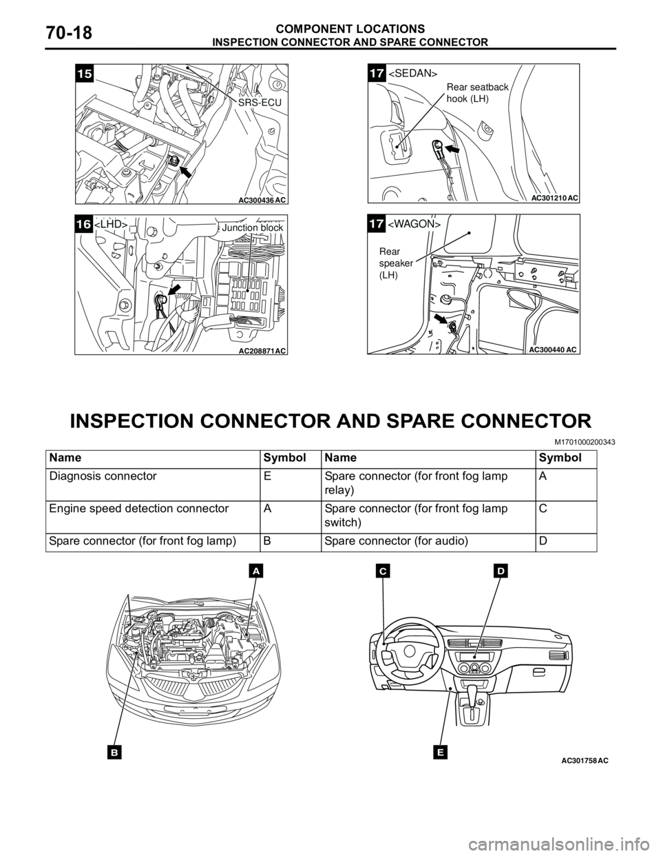
INSPECTION CONNECTOR AND SPARE CONNECTOR
M1701000200343
AC300436AC
15
SRS-ECU
AC208871AC
Junction block16
AC301210
17
AC
Rear seatback
hook (LH)
AC300440
17
AC
Rear
speaker
(LH)
Name Symbol Name Symbol
Diagnosis connector E Spare connector (for front fog lamp
relay)A
Engine speed detection connector A Spare connector (for front fog lamp
switch)C
Spare connector (for front fog lamp) B Spare connector (for audio) D
AC301758ACB
ADC
E
Page 608 of 788
OVERALL CONFIGURATION DIAGRAM
CONFIGURATION DIAGRAMS80-2
OVERALL CONFIGURATION DIAGRAM
OVERALL WIRING DIAGRAM M1801000100569
NOTE: .
1. This illustration shows only major wiring harnesses.
2. *: also equipped at the right side.
AC301175
AB
Front wiring
harness (RH)Control wiring
harnessInstrument panel
wiring harnessRoof wiring
harnessFloor wiring
harness (RH)
Battery wiring
harnessFront wiring
harness (LH)Front door
wiring harness Floor wiring
harness (LH)Fuel wiring
harnessRear door
wiring harness
Front bumper
wiring harness
Rear bumper
wiring harness
**
Page 609 of 788
OVERALL CONFIGURATION DIAGRAM
CONFIGURATION DIAGRAMS80-3
OVERALL WIRING DIAGRAM M1801000100581
NOTE: .
1. This illustration shows only major wiring harnesses.
2. *: also equipped at the right side.
AC301176AB
Front wiring
harness (RH)Control wiring
harnessInstrument panel
wiring harnessRoof wiring
harnessFloor wiring
harness (RH)
Battery wiring
harnessFront wiring
harness (LH)Front door
wiring harness Floor wiring
harness (LH)Fuel wiring
harnessRear door
wiring harness
Front bumper
wiring harness
Rear bumper
wiring harness
**

