Transmission MITSUBISHI LANCER 2005 User Guide
[x] Cancel search | Manufacturer: MITSUBISHI, Model Year: 2005, Model line: LANCER, Model: MITSUBISHI LANCER 2005Pages: 788, PDF Size: 45.98 MB
Page 171 of 788
32-1
GROUP 32
POWER PLANT
MOUNT
CONTENTS
GENERAL INFORMATION . . . . . . . .32-2
SERVICE SPECIFICATION . . . . . . . .32-3
SPECIAL TOOL . . . . . . . . . . . . . . . . .32-3
ENGINE MOUNTING . . . . . . . . . . . . .32-4
REMOVAL AND INSTALLATION . . . . . . . . 32-4
TRANSMISSION MOUNTING . . . . . .32-5
REMOVAL AND INSTALLATION . . . . . . . . 32-5
ENGINE ROLL STOPPER,
CENTERMEMBER . . . . . . . . . . . . . . .32-7
REMOVAL AND INSTALLATION . . . . . . . . 32-7
CROSSMEMBER . . . . . . . . . . . . . . . .32-8
REMOVAL AND INSTALLATION . . . . . . . . 32-8
Page 172 of 788
GENERAL INFORMATION
POWER PLANT MOUNT32-2
GENERAL INFORMATION
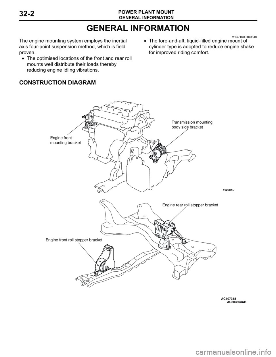
M1321000100340The engine mounting system employs the inertial
axis four-point suspension method, which is field
proven.
•The optimised locations of the front and rear roll
mounts well distribute their loads thereby
reducing engine idling vibrations.•The fore-and-aft, liquid-filled engine mount of
cylinder type is adopted to reduce engine shake
for improved riding comfort.
CONSTRUCTION DIAGRAM
AC107318
Y0290AU
AC303563
Engine front
mounting bracketTransmission mounting
body side bracket
Engine rear roll stopper bracket
Engine front roll stopper bracket
AB
Page 174 of 788
ENGINE MOUNTING
POWER PLANT MOUNT32-4
ENGINE MOUNTING
REMOVAL AND INSTALLATIONM1321001100440
CAUTION
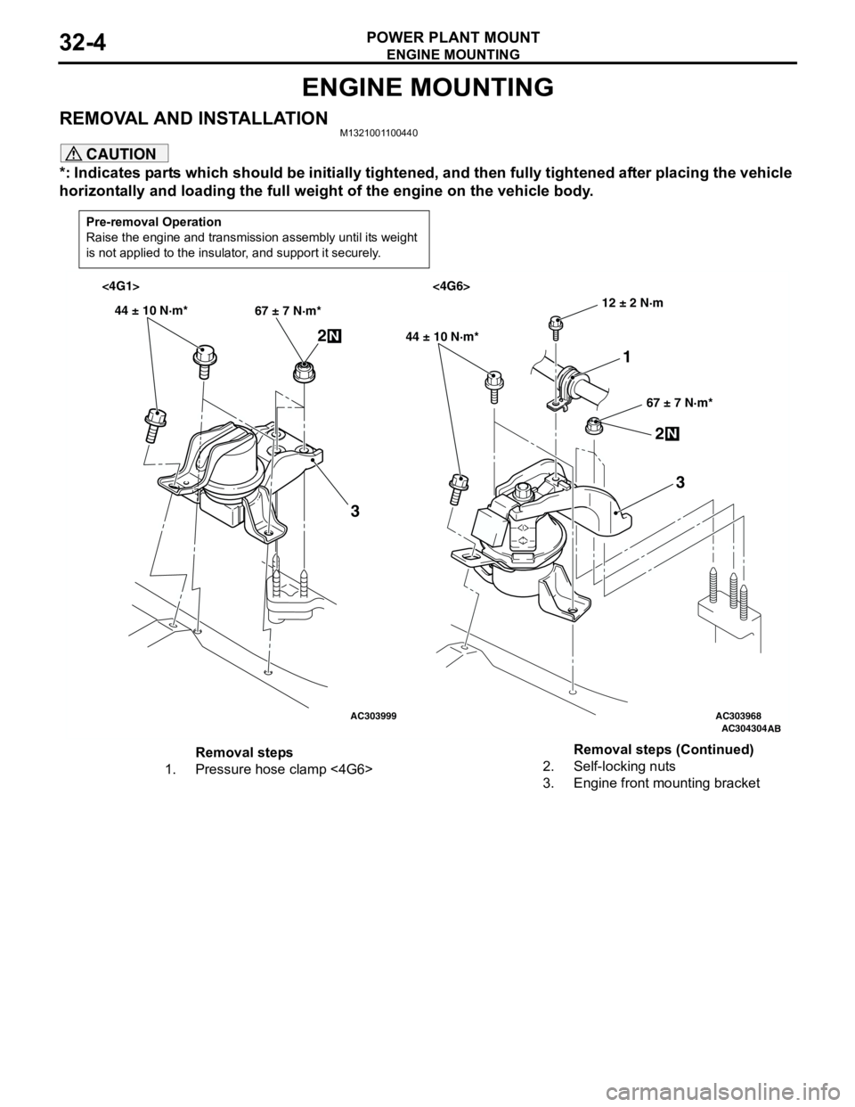
*: Indicates parts which should be initially tightened, and then fully tightened after placing the vehicle
horizontally and loading the full weight of the engine on the vehicle body.
Pre-removal Operation
Raise the engine and transmission assembly until its weight
is not applied to the insulator, and support it securely.
AC303999AC303968AC304304
AB
<4G1> <4G6>
44 ± 10 N·m*
67 ± 7 N·m*
2N
3
44 ± 10 N·m*
67 ± 7 N·m*
2N
3
12 ± 2 N·m
1
Removal steps
1. Pressure hose clamp <4G6>2. Self-locking nuts
3. Engine front mounting bracketRemoval steps (Continued)
Page 175 of 788
TRANSMISSION MOUNTING
POWER PLANT MOUNT32-5
TRANSMISSION MOUNTING
REMOVAL AND INSTALLATIONM1321001400430
CAUTION
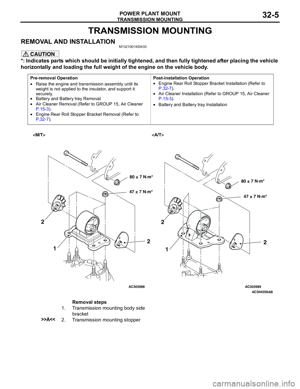
*: Indicates parts which should be initially tightened, and then fully tightened after placing the vehicle
horizontally and loading the full weight of the engine on the vehicle body.
Pre-removal Operation
•Raise the engine and transmission assembly until its
weight is not applied to the insulator, and support it
securely.
•Battery and Battery tray Removal
•Air Cleaner Removal (Refer to GROUP 15, Air Cleaner
P.15-3).
•Engine Rear Roll Stopper Bracket Removal (Refer to
P.32-7).Post-installation Operation
•Engine Rear Roll Stopper Bracket Installation (Refer to
P.32-7).
•Air Cleaner Installation (Refer to GROUP 15, Air Cleaner
P.15-3).
•Battery and Battery tray Installation
AC303988AC303989
AC304258
AB
80 ± 7 N·m*
47 ± 7 N·m*80 ± 7 N·m*
47 ± 7 N·m*
1
1 2
22
2
Removal steps
1. Transmission mounting body side
bracket
>>A<<2. Transmission mounting stopper
Page 176 of 788
TRANSMISSION MOUNTING
POWER PLANT MOUNT32-6
INSTALLATION SERVICE POINT
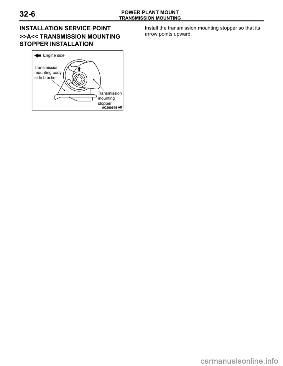
>>A<< TRANSMISSION MOUNTING
STOPPER INSTALLATIONInstall the transmission mounting stopper so that its
arrow points upward.
AC200645
Engine side
Transmission
mounting body
side bracket
Transmission
mounting
stopper
AB
Page 177 of 788
ENGINE ROLL STOPPER, CENTERMEMBER
POWER PLANT MOUNT32-7
ENGINE ROLL STOPPER, CENTERMEMBER
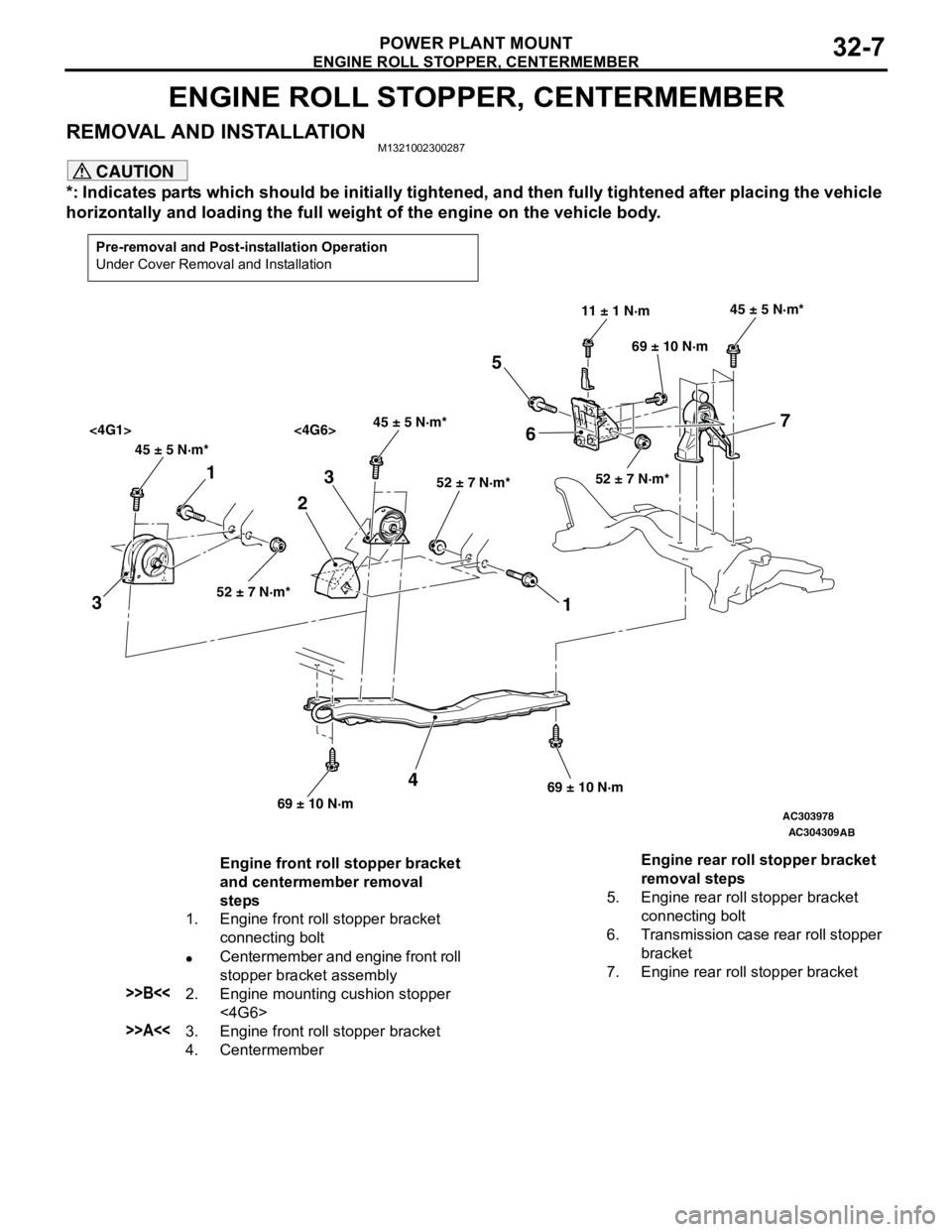
REMOVAL AND INSTALLATIONM1321002300287
CAUTION
*: Indicates parts which should be initially tightened, and then fully tightened after placing the vehicle
horizontally and loading the full weight of the engine on the vehicle body.
Pre-removal and Post-installation Operation
Under Cover Removal and Installation
AC303978
AC304309
45 ± 5 N·m*45 ± 5 N·m*
<4G1> <4G6>
52 ± 7 N·m*52 ± 7 N·m*
45 ± 5 N·m*
52 ± 7 N·m*
11 ± 1 N·m
69 ± 10 N·m
69 ± 10 N·m69 ± 10 N·m
1
32
1 3
4
5
67
AB
Engine front roll stopper bracket
and centermember removal
steps
1. Engine front roll stopper bracket
connecting bolt
•Centermember and engine front roll
stopper bracket assembly
>>B<<2. Engine mounting cushion stopper
<4G6>
>>A<<3. Engine front roll stopper bracket
4. CentermemberEngine rear roll stopper bracket
removal steps
5. Engine rear roll stopper bracket
connecting bolt
6. Transmission case rear roll stopper
bracket
7. Engine rear roll stopper bracket
Page 181 of 788
Page 194 of 788
Page 198 of 788
Page 426 of 788
COMBINATION METER ASSEMBLY
CHASSIS ELECTRICAL54A-38
TECHNICAL DESCRIPTION (COMMENT)
The engine-ECU and its associated components, the
combination meter assembly, the wiring harness, or
the connector(s) may be defective.
TROUBLESHOOTING HINTS
•Malfunction of the vehicle speed sensor
•Malfunction of the engine-ECU
•Malfunction of the combination meter assembly
•The wiring harness or connectors may have
loose, corroded, or damaged terminals, or
terminals pushed back in the connector.
DIAGNOSIS PROCEDURE
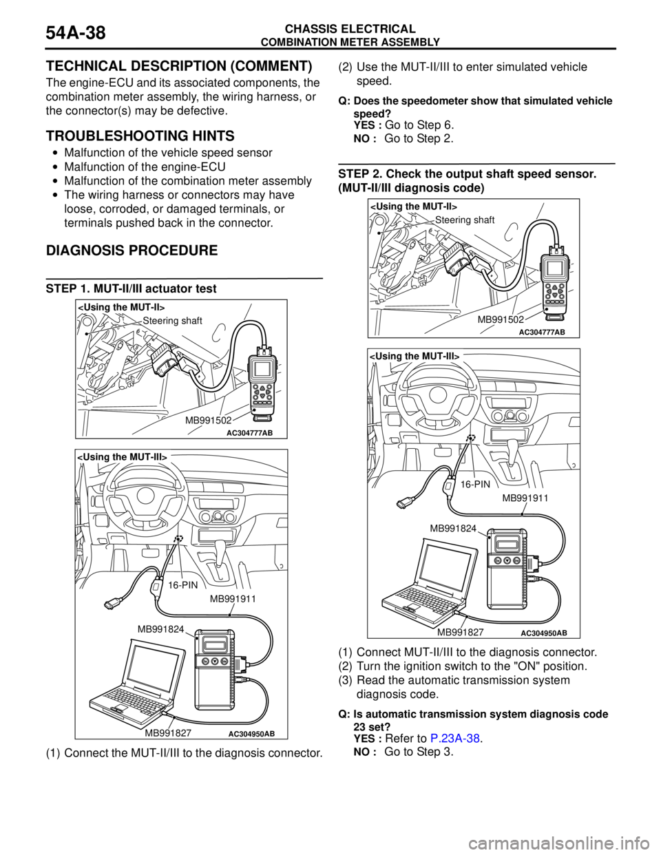
STEP 1. MUT-II/III actuator test
(1) Connect the MUT-II/III to the diagnosis connector.(2) Use the MUT-II/III to enter simulated vehicle
speed.
Q: Does the speedometer show that simulated vehicle
speed?
YES :
Go to Step 6.
NO : Go to Step 2.
STEP 2. Check the output shaft speed sensor.
(MUT-II/III diagnosis code)
(1) Connect MUT-II/III to the diagnosis connector.
(2) Turn the ignition switch to the "ON" position.
(3) Read the automatic transmission system
diagnosis code.
Q: Is automatic transmission system diagnosis code
23 set?
YES :
Refer to P.23A-38.
NO : Go to Step 3.
AC304777
Steering shaft
AB
MB991502
AC304950
MB991911
16-PIN
MB991827 MB991824
AB
AC304777
Steering shaft
AB
MB991502
AC304950
MB991911
16-PIN
MB991827 MB991824
AB