electrical MITSUBISHI LANCER 2005 User Guide
[x] Cancel search | Manufacturer: MITSUBISHI, Model Year: 2005, Model line: LANCER, Model: MITSUBISHI LANCER 2005Pages: 788, PDF Size: 45.98 MB
Page 73 of 788
CHARGING SYSTEM
ENGINE ELECTRICAL16-9
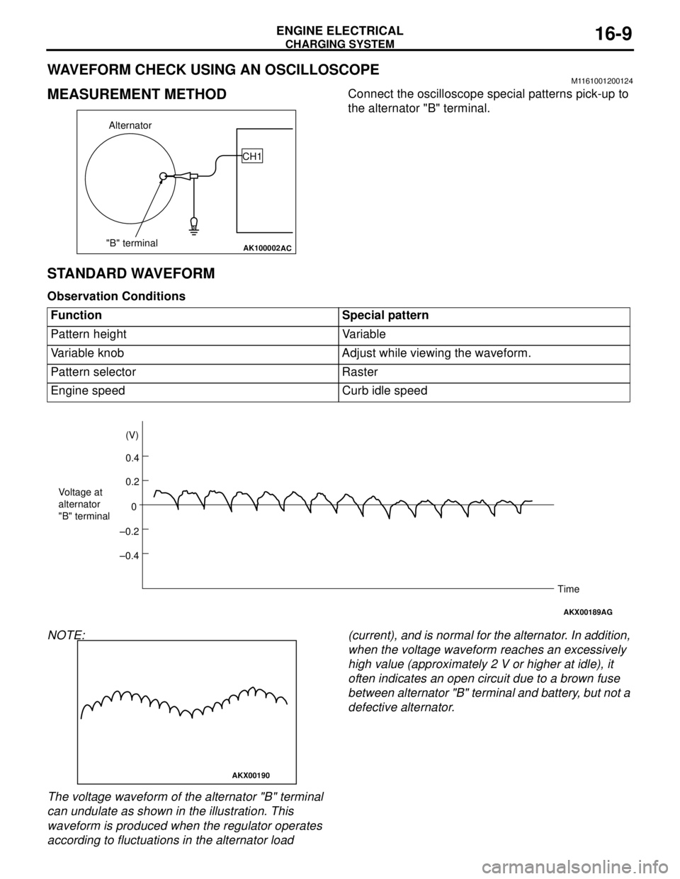
WAVEFORM CHECK USING AN OSCILLOSCOPEM1161001200124
MEASUREMENT METHODConnect the oscilloscope special patterns pick-up to
the alternator "B" terminal.
STANDARD WAVEFORM
Observation Conditions
NOTE:
The voltage waveform of the alternator "B" terminal
can undulate as shown in the illustration. This
waveform is produced when the regulator operates
according to fluctuations in the alternator load (current), and is normal for the alternator. In addition,
when the voltage waveform reaches an excessively
high value (approximately 2 V or higher at idle), it
often indicates an open circuit due to a brown fuse
between alternator "B" terminal and battery, but not a
defective alternator.
AK100002
Alternator
"B" terminalCH1
AC
Function Special pattern
Pattern height Variable
Variable knob Adjust while viewing the waveform.
Pattern selector Raster
Engine speed Curb idle speed
AKX00189
0.4 (V)
0.2
0
–0.2
–0.4 Voltage at
alternator
"B" terminal
Time
AG
AKX00190
Page 74 of 788
CHARGING SYSTEM
ENGINE ELECTRICAL16-10
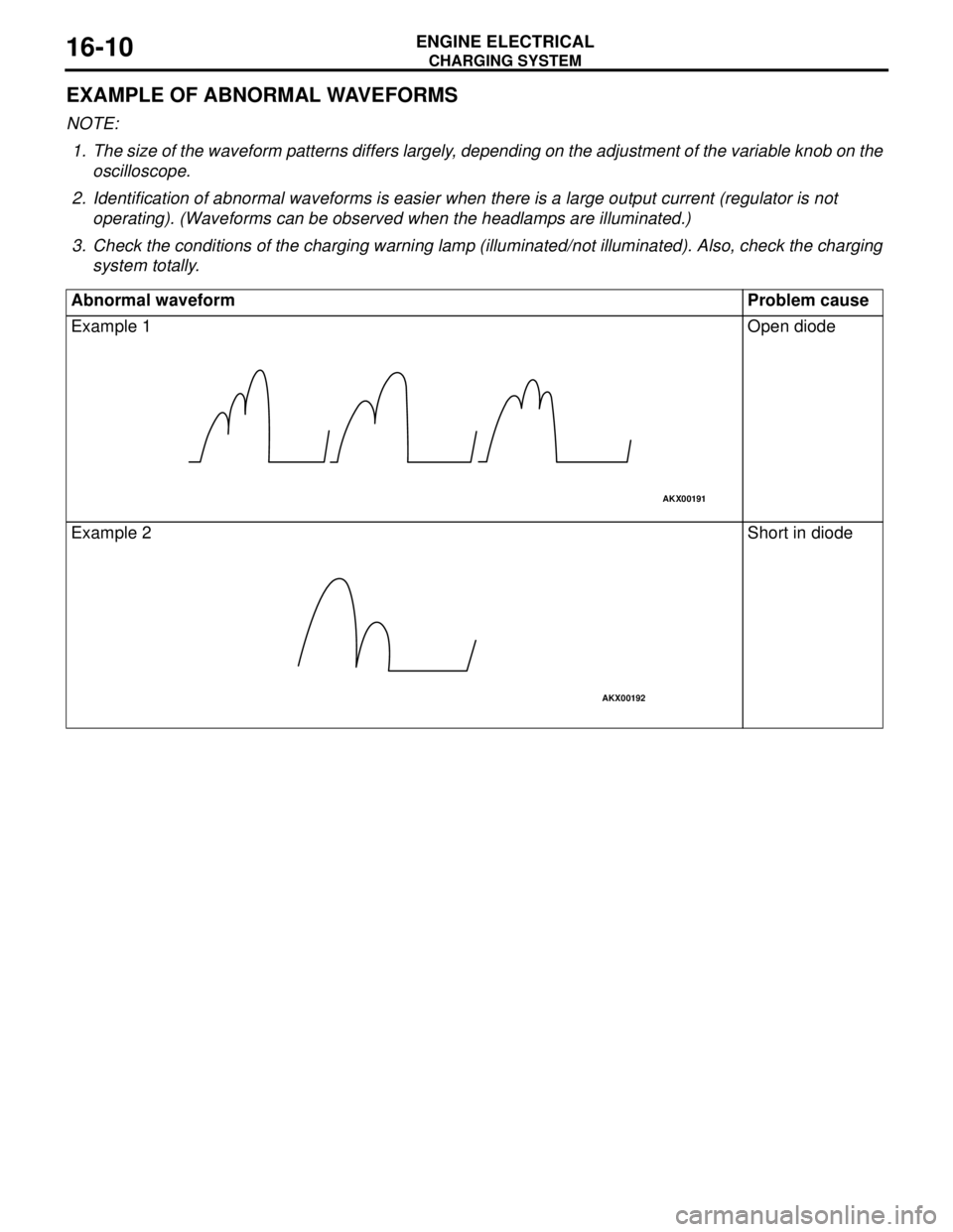
EXAMPLE OF ABNORMAL WAVEFORMS
NOTE: .
1. The size of the waveform patterns differs largely, depending on the adjustment of the variable knob on the
oscilloscope.
2. Identification of abnormal waveforms is easier when there is a large output current (regulator is not
operating). (Waveforms can be observed when the headlamps are illuminated.)
3. Check the conditions of the charging warning lamp (illuminated/not illuminated). Also, check the charging
system totally.
Abnormal waveform Problem cause
Example 1 Open diode
Example 2 Short in diode
AKX00191
AKX00192
Page 75 of 788
CHARGING SYSTEM
ENGINE ELECTRICAL16-11
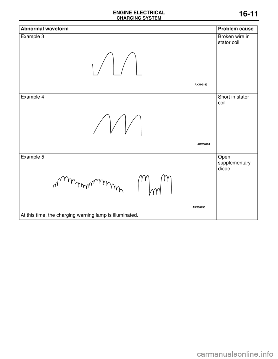
Example 3 Broken wire in
stator coil
Example 4 Short in stator
coil
Example 5
At this time, the charging warning lamp is illuminated.Open
supplementary
diode Abnormal waveform Problem cause
AKX00193
AKX00194
AKX00195
Page 76 of 788
CHARGING SYSTEM
ENGINE ELECTRICAL16-12
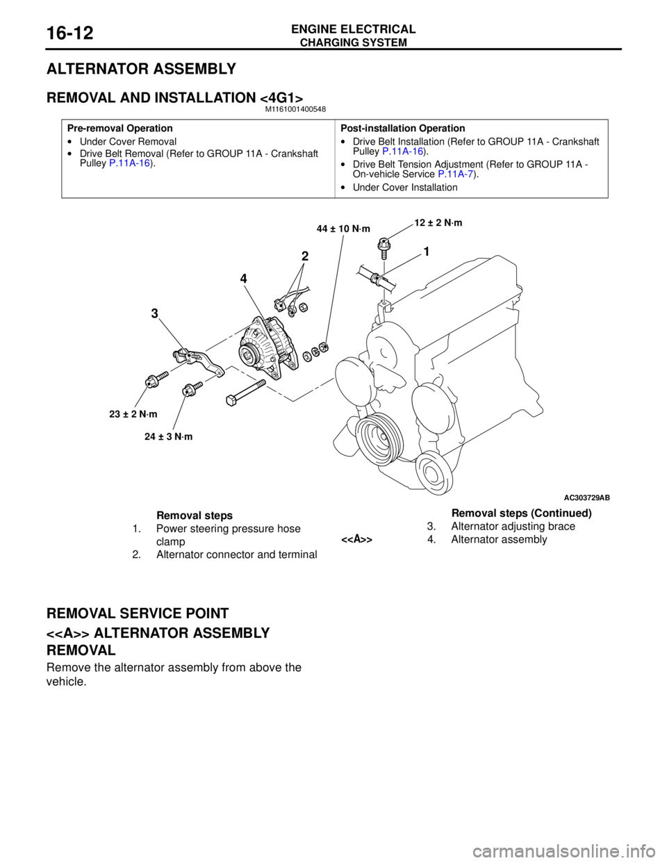
ALTERNATOR ASSEMBLY
REMOVAL AND INSTALLATION <4G1>M1161001400548
REMOVAL SERVICE POINT
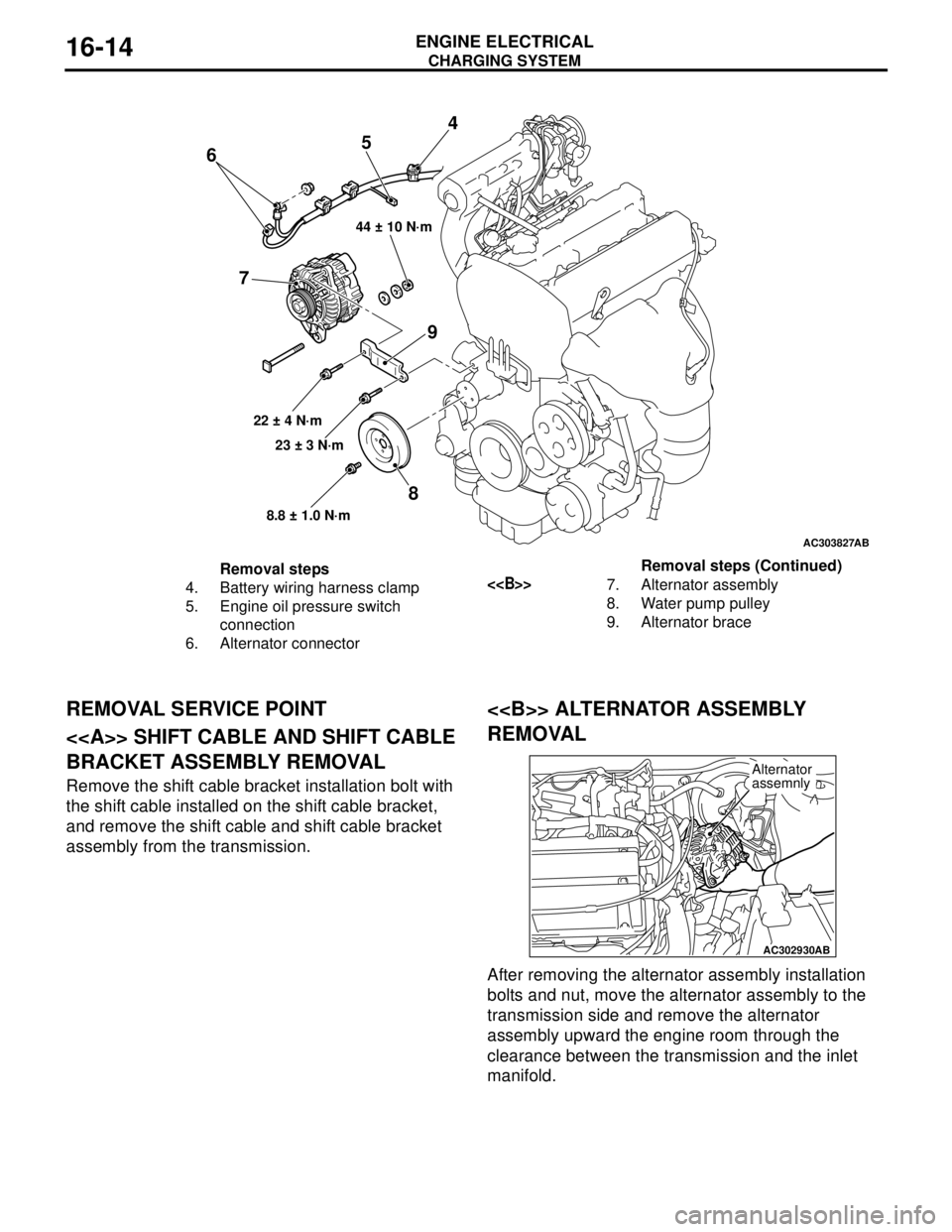
<> ALTERNATOR ASSEMBLY
REMOVAL
Remove the alternator assembly from above the
vehicle.
Pre-removal Operation
•Under Cover Removal
•Drive Belt Removal (Refer to GROUP 11A - Crankshaft
Pulley P.11A-16).Post-installation Operation
•Drive Belt Installation (Refer to GROUP 11A - Crankshaft
Pulley P.11A-16).
•Drive Belt Tension Adjustment (Refer to GROUP 11A -
On-vehicle Service P.11A-7).
•Under Cover Installation
AC303729
1
2
4
3
44 ± 10 N·m
23 ± 2 N·m
24 ± 3 N·m12 ± 2 N·m
AB
Removal steps
1. Power steering pressure hose
clamp
2. Alternator connector and terminal3. Alternator adjusting brace
<>4. Alternator assemblyRemoval steps (Continued)
Page 77 of 788
CHARGING SYSTEM
ENGINE ELECTRICAL16-13
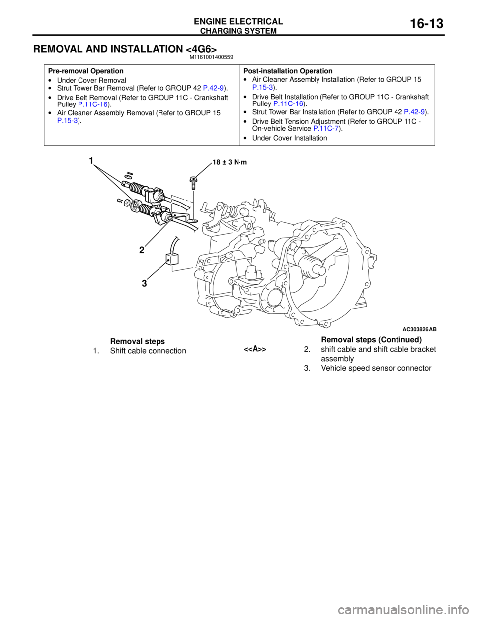
REMOVAL AND INSTALLATION <4G6>M1161001400559
Pre-removal Operation
•Under Cover Removal
•Strut Tower Bar Removal (Refer to GROUP 42 P.42-9).
•Drive Belt Removal (Refer to GROUP 11C - Crankshaft
Pulley P.11C-16).
•Air Cleaner Assembly Removal (Refer to GROUP 15
P.15-3).Post-installation Operation
•Air Cleaner Assembly Installation (Refer to GROUP 15
P.15-3).
•Drive Belt Installation (Refer to GROUP 11C - Crankshaft
Pulley P.11C-16).
•Strut Tower Bar Installation (Refer to GROUP 42 P.42-9).
•Drive Belt Tension Adjustment (Refer to GROUP 11C -
On-vehicle Service P.11C-7).
•Under Cover Installation
AC303826
1
2
318 ± 3 N·m
AB
Removal steps
1. Shift cable connection<>2. shift cable and shift cable bracket
assembly
3. Vehicle speed sensor connectorRemoval steps (Continued)
Page 78 of 788
Page 79 of 788
CHARGING SYSTEM
ENGINE ELECTRICAL16-15
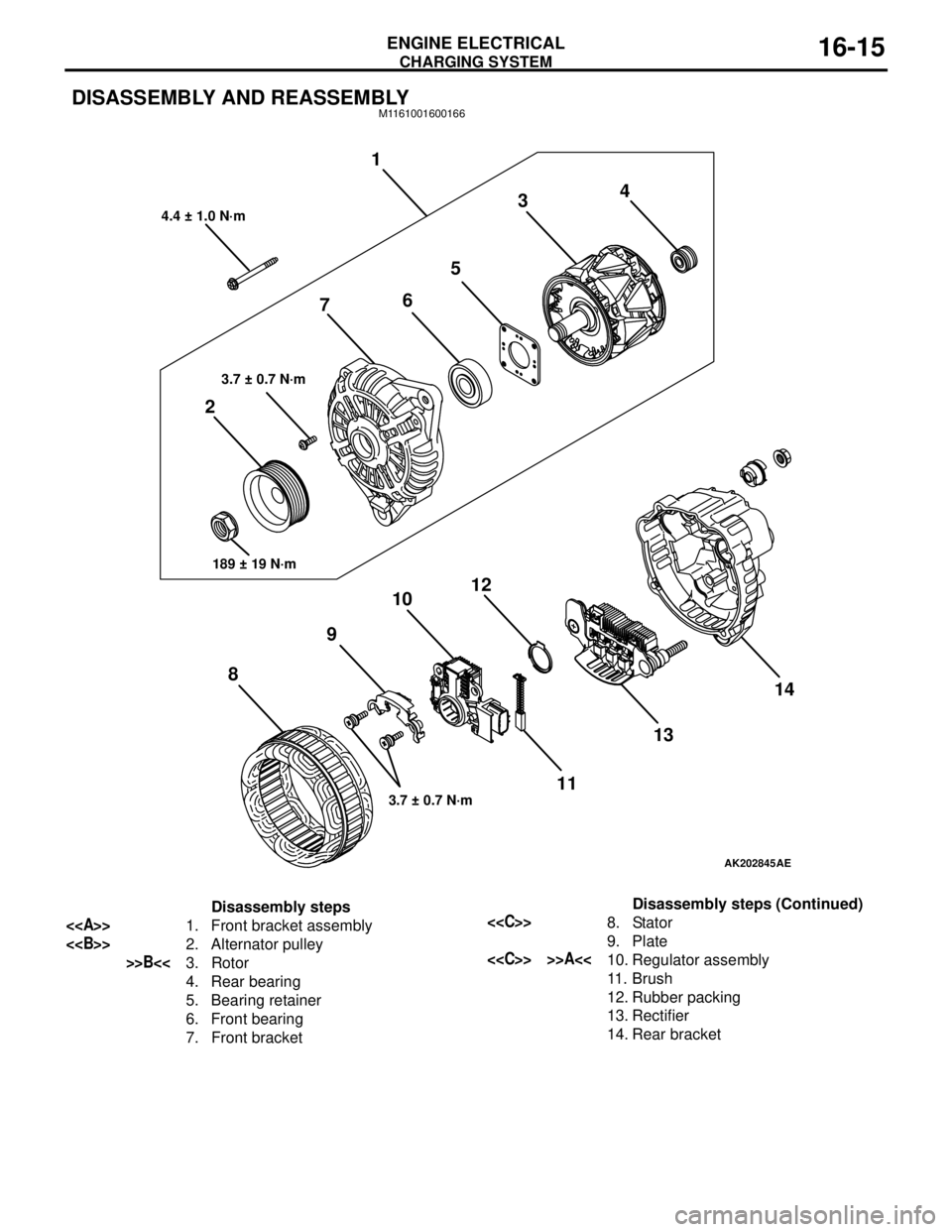
DISASSEMBLY AND REASSEMBLYM1161001600166
AK202845
1
234
5
6
7
8910
11 12
1314
AE
4.4 ± 1.0 N·m
3.7 ± 0.7 N·m
189 ± 19 N·m
3.7 ± 0.7 N·m
Disassembly steps
<>1. Front bracket assembly
<>2. Alternator pulley
>>B<<3. Rotor
4. Rear bearing
5. Bearing retainer
6. Front bearing
7. Front bracket
<
9. Plate
<
11 . B r u s h
12. Rubber packing
13. Rectifier
14. Rear bracketDisassembly steps (Continued)
Page 80 of 788
Page 81 of 788
CHARGING SYSTEM
ENGINE ELECTRICAL16-17
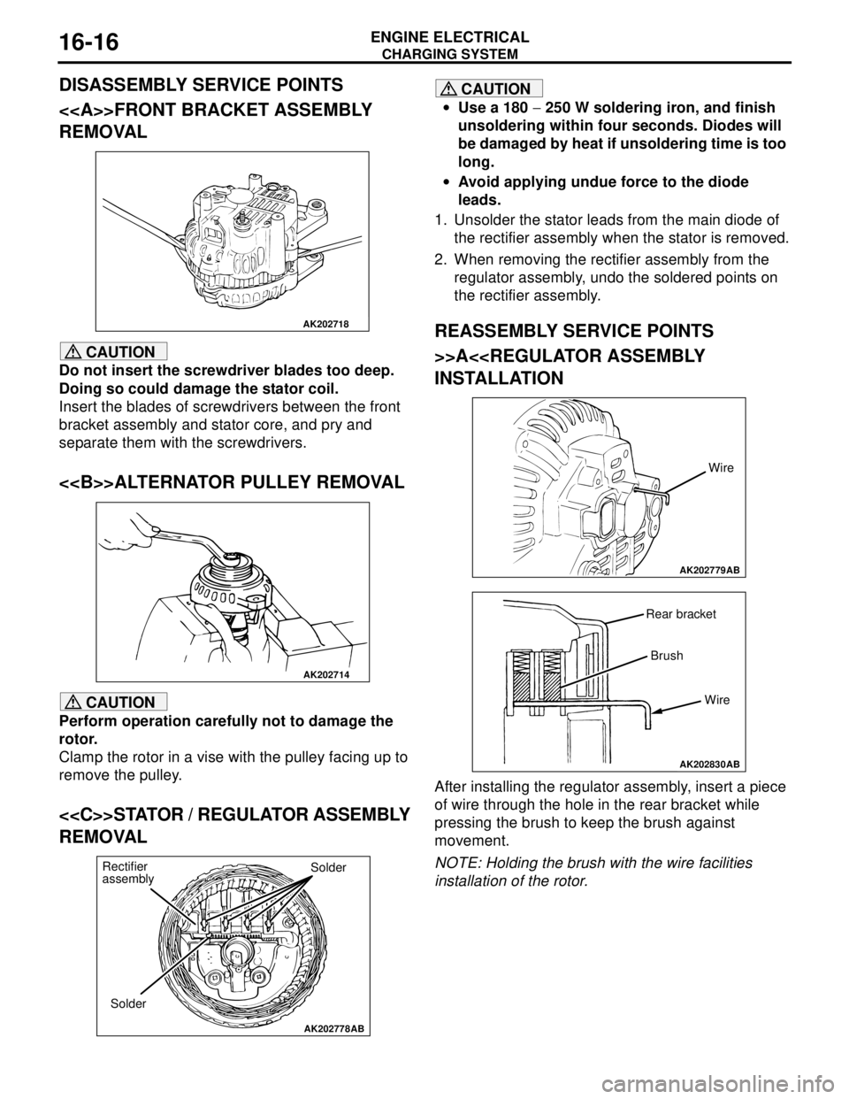
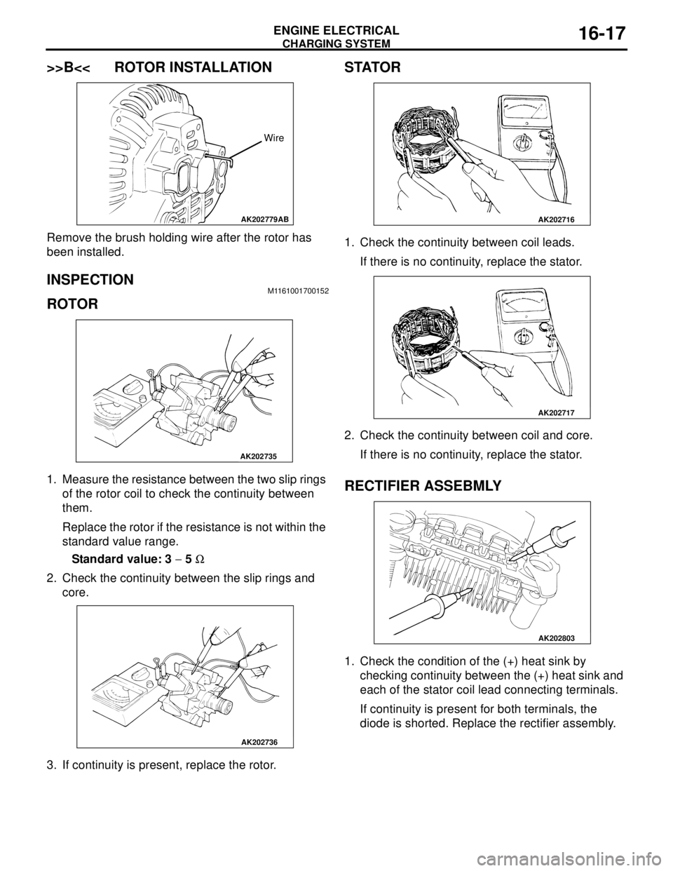
>>B<< ROTOR INSTALLATION
Remove the brush holding wire after the rotor has
been installed.
INSPECTION M1161001700152
ROTOR
1. Measure the resistance between the two slip rings
of the rotor coil to check the continuity between
them.
Replace the rotor if the resistance is not within the
standard value range.
Standard value: 3 − 5 Ω
2. Check the continuity between the slip rings and
core.
3. If continuity is present, replace the rotor.
STATOR
1. Check the continuity between coil leads.
If there is no continuity, replace the stator.
2. Check the continuity between coil and core.
If there is no continuity, replace the stator.
RECTIFIER ASSEBMLY
1. Check the condition of the (+) heat sink by
checking continuity between the (+) heat sink and
each of the stator coil lead connecting terminals.
If continuity is present for both terminals, the
diode is shorted. Replace the rectifier assembly.
AK202779
Wire
AB
AK202735
AK202736
AK202716
AK202717
AK202803
Page 82 of 788
CHARGING SYSTEM
ENGINE ELECTRICAL16-18
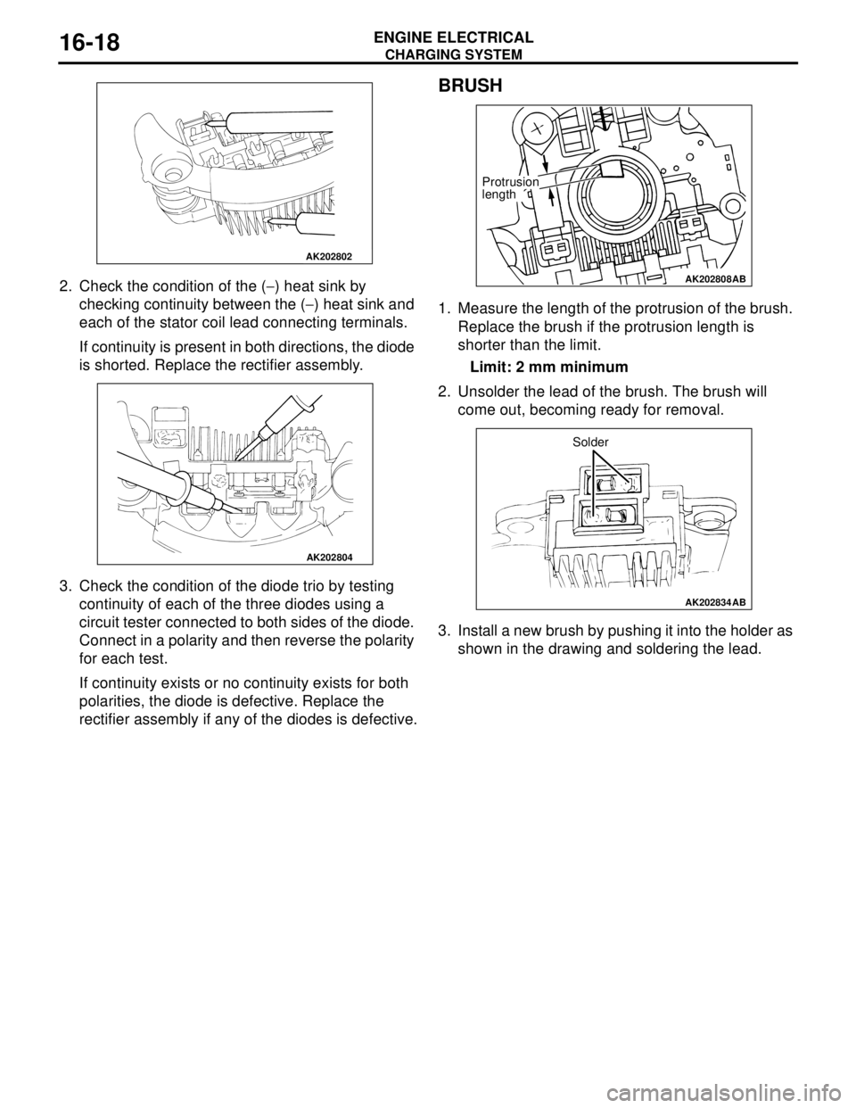
2. Check the condition of the (−) heat sink by
checking continuity between the (−) heat sink and
each of the stator coil lead connecting terminals.
If continuity is present in both directions, the diode
is shorted. Replace the rectifier assembly.
3. Check the condition of the diode trio by testing
continuity of each of the three diodes using a
circuit tester connected to both sides of the diode.
Connect in a polarity and then reverse the polarity
for each test.
If continuity exists or no continuity exists for both
polarities, the diode is defective. Replace the
rectifier assembly if any of the diodes is defective.
BRUSH
1. Measure the length of the protrusion of the brush.
Replace the brush if the protrusion length is
shorter than the limit.
Limit: 2 mm minimum
2. Unsolder the lead of the brush. The brush will
come out, becoming ready for removal.
3. Install a new brush by pushing it into the holder as
shown in the drawing and soldering the lead.
AK202802
AK202804
AK202808
Protrusion
length
AB
AK202834
Solder
AB