wheel alignment MITSUBISHI LANCER 2005 User Guide
[x] Cancel search | Manufacturer: MITSUBISHI, Model Year: 2005, Model line: LANCER, Model: MITSUBISHI LANCER 2005Pages: 788, PDF Size: 45.98 MB
Page 201 of 788
34-1
GROUP 34
REAR SUSPENSION
CONTENTS
GENERAL INFORMATION . . . . . . . .34-2
SERVICE SPECIFICATIONS . . . . . . .34-3
LUBRICANT . . . . . . . . . . . . . . . . . . . .34-3
SPECIAL TOOLS . . . . . . . . . . . . . . . .34-4
ON-VEHICLE SERVICE . . . . . . . . . . .34-5
REAR WHEEL ALIGNMENT CHECK
AND ADJUSTMENT . . . . . . . . . . . . . . . . . . 34-5
CONTROL LINK PILLOW BALL BUSHING
AXIAL PLAY CHECK
UPPER ARM PILLOW BALL BUSHING
AXIAL PLAY CHECK
LOWER ARM PILLOW BALL BUSHING
AXIAL PLAY CHECK . . . . . . . . . . . . . . . . . 34-7
STABILIZER LINK BALL JOINT
DUST COVER INSPECTION . . . . . . . . . . . 34-7
CONTROL LINK, UPPER ARM AND
LOWER ARM . . . . . . . . . . . . . . . . . . .34-8
REMOVAL AND INSTALLATION . . . . . . . . 34-8
INSPECTION . . . . . . . . . . . . . . . . . . . . . . . . 34-9
LOWER ARM BUSHING AND LOWER
ARM PILLOW BALL BUSHING
REPLACEMENT . . . . . . . . . . . . . . . . . . . . . 34-10
TRAILING ARM ASSEMBLY . . . . . . .34-12
REMOVAL AND INSTALLATION . . . . . . . . 34-12
INSPECTION . . . . . . . . . . . . . . . . . . . . . . . . 34-13
TRAILING ARM BUSHING
REPLACEMENT . . . . . . . . . . . . . . . . . . . . . 34-13
SHOCK ABSORBER ASSEMBLY . . .34-15
REMOVAL AND INSTALLATION . . . . . . . . 34-15
INSPECTION . . . . . . . . . . . . . . . . . . . . . . . . 34-16
DISASSEMBLY AND REASSEMBLY . . . . . 34-17
STABILIZER BAR. . . . . . . . . . . . . . . .34-20
REMOVAL AND INSTALLATION . . . . . . . . 34-20
INSPECTION . . . . . . . . . . . . . . . . . . . . . . . . 34-21
STABILIZER LINK BALL JOINT
DUST COVER REPLACEMENT . . . . . . . . . 34-21
Page 204 of 788
SPECIAL TOOLS
REAR SUSPENSION34-4
SPECIAL TOOLS
M1341000600392
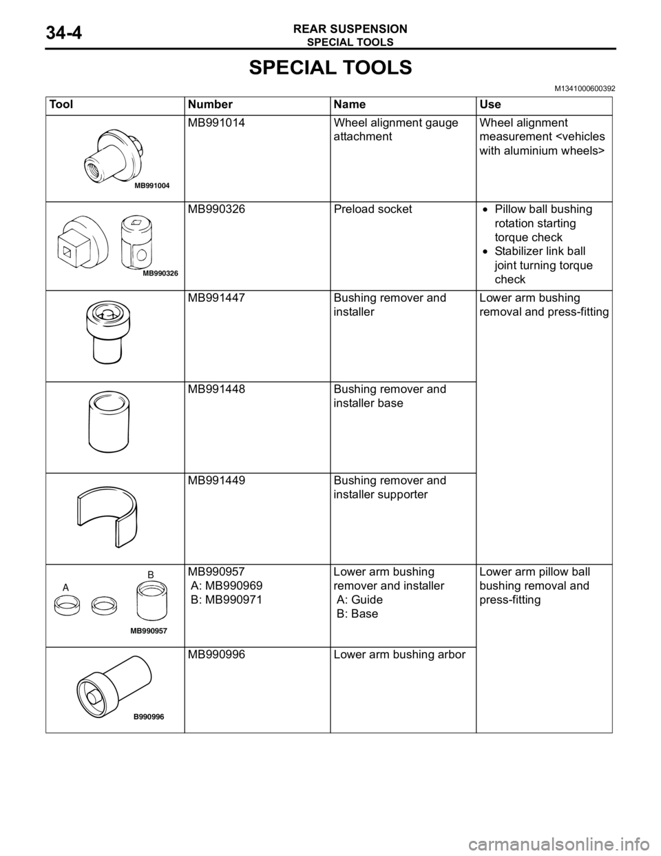
Tool Number Name Use
MB991014 Wheel alignment gauge
attachmentWheel alignment
measurement
MB990326 Preload socket•Pillow ball bushing
rotation starting
torque check
•Stabilizer link ball
joint turning torque
check
MB991447 Bushing remover and
installerLower arm bushing
removal and press-fitting
MB991448 Bushing remover and
installer base
MB991449 Bushing remover and
installer supporter
MB990957
A: MB990969
B: MB990971Lower arm bushing
remover and installer
A: Guide
B: BaseLower arm pillow ball
bushing removal and
press-fitting
MB990996 Lower arm bushing arbor
MB991004
MB990326
MB990957
AB
B990996
Page 205 of 788
ON-VEHICLE SERVICE
REAR SUSPENSION34-5
ON-VEHICLE SERVICE
REAR WHEEL ALIGNMENT CHECK AND
ADJUSTMENT
M1341011000372
Measure wheel alignment with an alignment
equipment on level earth.
The rear suspension, wheels, and tyres should be
serviced to the normal condition prior to wheel
alignment measurement.
CAMBER
Standard value: -0° 40' ± 30' (Left/right
deviation within 30')
CAUTION
Never subject the wheel bearings to the vehicle
load when the rear wheel hub nuts (self-locking
nuts) or special tool wheel alignment gauge
attachment (MB991014) are loosened.
NOTE:
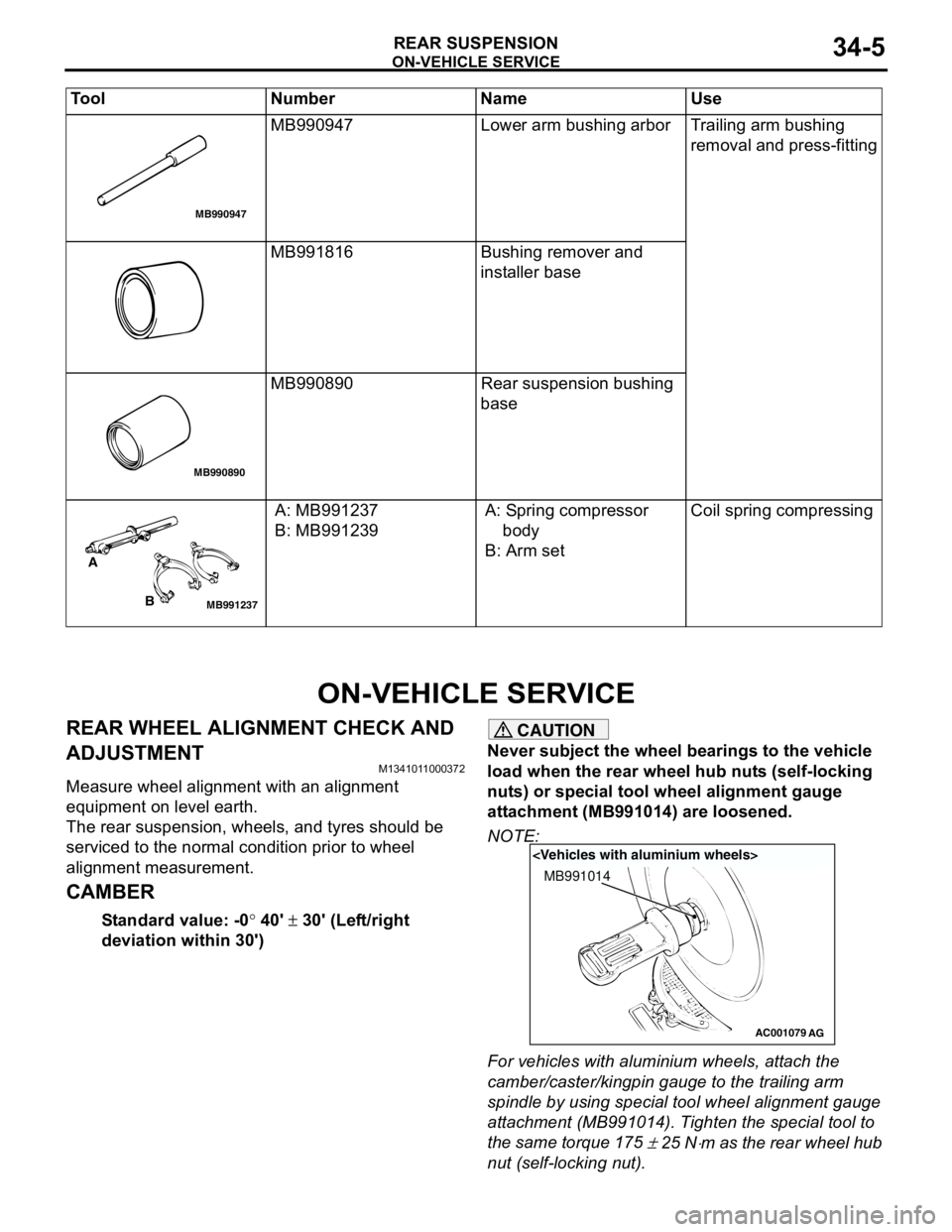
For vehicles with aluminium wheels, attach the
camber/caster/kingpin gauge to the trailing arm
spindle by using special tool wheel alignment gauge
attachment (MB991014). Tighten the special tool to
the same torque 175
± 25 N⋅m as the rear wheel hub
nut (self-locking nut). MB990947 Lower arm bushing arbor Trailing arm bushing
removal and press-fitting
MB991816 Bushing remover and
installer base
MB990890 Rear suspension bushing
base
A: MB991237
B: MB991239A: Spring compressor
body
B: Arm setCoil spring compressing Tool Number Name Use
MB990947
MB990890
MB991237
A
B
AC001079
MB991014
AG
Page 208 of 788
CONTROL LINK, UPPER ARM AND LOWER ARM
REAR SUSPENSION34-8
CONTROL LINK, UPPER ARM AND LOWER ARM
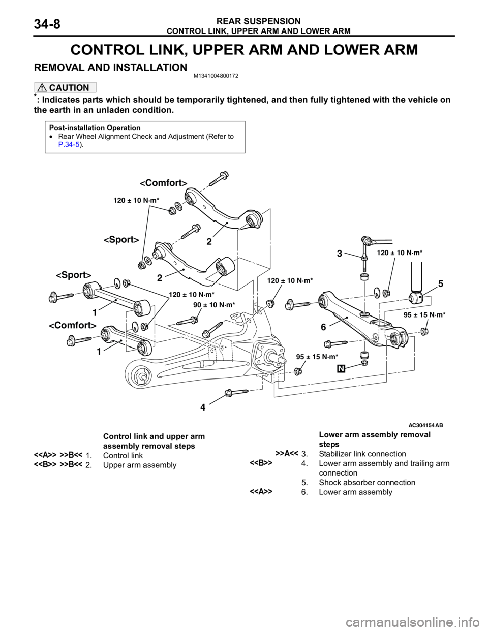
REMOVAL AND INSTALLATIONM1341004800172
CAUTION
*: Indicates parts which should be temporarily tightened, and then fully tightened with the vehicle on
the earth in an unladen condition.
Post-installation Operation
•Rear Wheel Alignment Check and Adjustment (Refer to
P.34-5).
AC304154
12
3
45
6
AB
120 ± 10 N·m*
95 ± 15 N·m* 120 ± 10 N·m* 120 ± 10 N·m*
95 ± 15 N·m*
90 ± 10 N·m*120 ± 10 N·m*
N
Control link and upper arm
assembly removal steps
<> >>B<<1. Control link
<> >>B<<2. Upper arm assemblyLower arm assembly removal
steps
>>A<<3. Stabilizer link connection
<>4. Lower arm assembly and trailing arm
connection
5. Shock absorber connection
<>6. Lower arm assembly
Page 212 of 788

TRAILING ARM ASSEMBLY
REAR SUSPENSION34-12
TRAILING ARM ASSEMBLY
REMOVAL AND INSTALLATIONM1341002200594
CAUTION
*: Indicates parts which should be temporarily tightened, and then fully tightened with the vehicle on
the earth in the unladen condition.
Pre-removal Operation
•Brake Fluid Draining
•Rear Hub Assembly Removal (Refer to GROUP 27, Rear
Axle Hub Assembly P.27-5).Post-installation Operation
•Rear Hub Assembly Installation (Refer to GROUP 27,
Rear Axle Hub Assembly P.27-5).
•Brake Fluid Supplying and Bleeding (Refer to GROUP
35A, On-vehicle Service − Bleeding P.35A-6).
•Rear Wheel Alignment Check and Adjustment (Refer to
P.34-5).
•Parking Brake Lever Stroke Adjustment (Refer to GROUP
36, On-vehicle Service − Parking Brake Lever Stroke
Check and Adjustment P.36-3).
AC101449
AC301223
AC304155AB
90 ± 10 N·m*
120 ± 10 N·m*
95 ± 15 N·m*63 ± 7 N·m
6 78
1 1011
23
4
120 ± 10 N·m*
15 ± 2 N·m
N
9
5
Removal steps
<>•Lifting point
1. Rear ABS Sensor (Refer to
GROUP 35B, ABS Sensor
P.35B-71).
2. Parking brake cable
3. Brake hose and trailing arm
connection
4. Rear parking brake assembly>>A<<5. Lower arm assembly and stabilizer
link connection
6. Lower arm assembly and shock
absorber connection
7. Control link and trailing arm
connection
8. Upper arm assembly and trailing
arm connection Removal steps (Continued)
Page 258 of 788
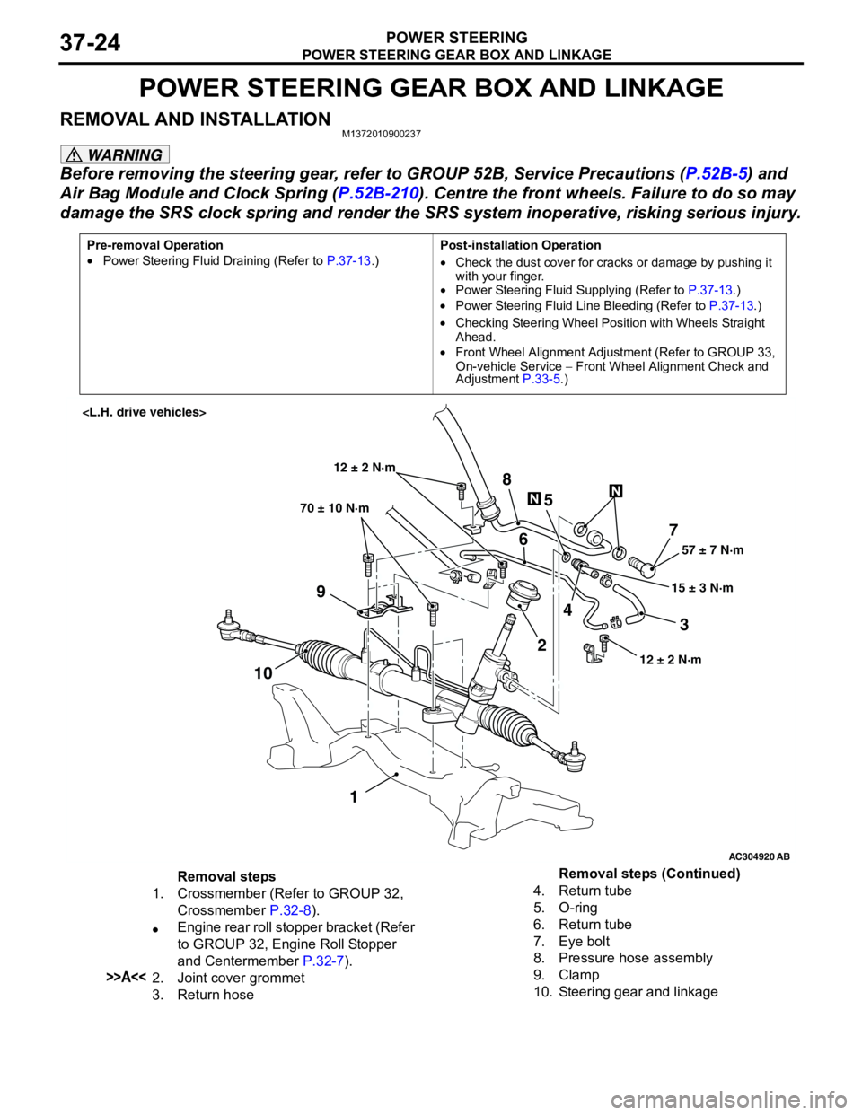
POWER STEERING GEAR BOX AND LINKAGE
POWER STEERING37-24
POWER STEERING GEAR BOX AND LINKAGE
REMOVAL AND INSTALLATIONM1372010900237
WARNING
Before removing the steering gear, refer to GROUP 52B, Service Precautions (P.52B-5) and
Air Bag Module and Clock Spring (P.52B-210). Centre the front wheels. Failure to do so may
damage the SRS clock spring and render the SRS system inoperative, risking serious injury.
Pre-removal Operation
•Power Steering Fluid Draining (Refer to P.37-13.)Post-installation Operation
•Check the dust cover for cracks or damage by pushing it
with your finger.
•Power Steering Fluid Supplying (Refer to P.37-13.)
•Power Steering Fluid Line Bleeding (Refer to P.37-13.)
•Checking Steering Wheel Position with Wheels Straight
Ahead.
•Front Wheel Alignment Adjustment (Refer to GROUP 33,
On-vehicle Service − Front Wheel Alignment Check and
Adjustment P.33-5.)
AC304920
AB
57 ± 7 N·m
15 ± 3 N·m 70 ± 10 N·m
7
3 8
5
6
9
1024
1
12 ± 2 N·m
12 ± 2 N·m
Removal steps
1. Crossmember (Refer to GROUP 32,
Crossmember P.32-8).
•Engine rear roll stopper bracket (Refer
to GROUP 32, Engine Roll Stopper
and Centermember P.32-7).
>>A<<2. Joint cover grommet
3. Return hose4. Return tube
5. O-ring
6. Return tube
7. Eye bolt
8. Pressure hose assembly
9. Clamp
10. Steering gear and linkageRemoval steps (Continued)