Air con MITSUBISHI LANCER 2005 Workshop Manual
[x] Cancel search | Manufacturer: MITSUBISHI, Model Year: 2005, Model line: LANCER, Model: MITSUBISHI LANCER 2005Pages: 788, PDF Size: 45.98 MB
Page 623 of 788
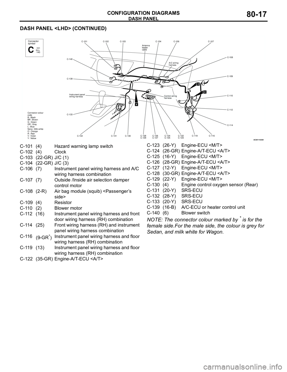
DASH PANEL
CONFIGURATION DIAGRAMS80-17
DASH PANEL
NOTE: The connector colour marked by
* is for the
female side.For the male side, the colour is grey for
Sedan, and milk white for Wagon.
AC301143
C-140C-102C-103 C-101
C-132 C-139
C-130 Y
4
Connector
symbol
-101
thru
-140C
Connector colour
code
B : Black
BR : Brown
G : Green
GR : Gray
L : Blue
None : Milk white
O : Orange
R : Red
V : Violet
Y : Yellow
Instrument panel
wiring harness
C-131
C-133
AB
C-104 C-106 C-107
C-109
C-110
C-112
C-114
C-116
C-119 C-126
C-127 C-128
C-129
2
C-108
C-124
C-125C-122
C-123
3
Control wiring
harness
A/C wiring
harness
Antenna
feeder
cable
C-101 (4) Hazard warning lamp switch
C-102 (4) Clock
C-103 (22-GR) J/C (1)
C-104 (22-GR) J/C (3)
C-106 (7) Instrument panel wiring harness and A/C
wiring harness combination
C-107 (7) Outside /Inside air selection damper
control motor
C-108 (2-R) Air bag module (squib)
C-109 (4) Resistor
C-110 (2) Blower motor
C-112 (16) Instrument panel wiring harness and front
door wiring harness (RH) combination
C-114 (25) Front wiring harness (RH) and instrument
panel wiring harness combination
C-116
(9-GR
*)Instrument panel wiring harness and floor
wiring harness (RH) combination
C-119 (13) Instrument panel wiring harness and floor
wiring harness (RH) combination
C-122 (35-GR) Engine-A/T-ECU C-123 (26-Y) Engine-ECU
C-124 (26-GR) Engine-A/T-ECU
C-125 (16-Y) Engine-ECU
C-126 (28-GR) Engine-A/T-ECU
C-127 (12-Y) Engine-ECU
C-128 (30-GR) Engine-A/T-ECU
C-129 (22-Y) Engine-ECU
C-130 (4) Engine control oxygen sensor (Rear)
C-131 (20-Y) SRS-ECU
C-132 (28-Y) SRS-ECU
C-133 (20-Y) SRS-ECU
C-139 (16-B) A/C-ECU or heater control unit
C-140 (6) Blower switch
Page 624 of 788
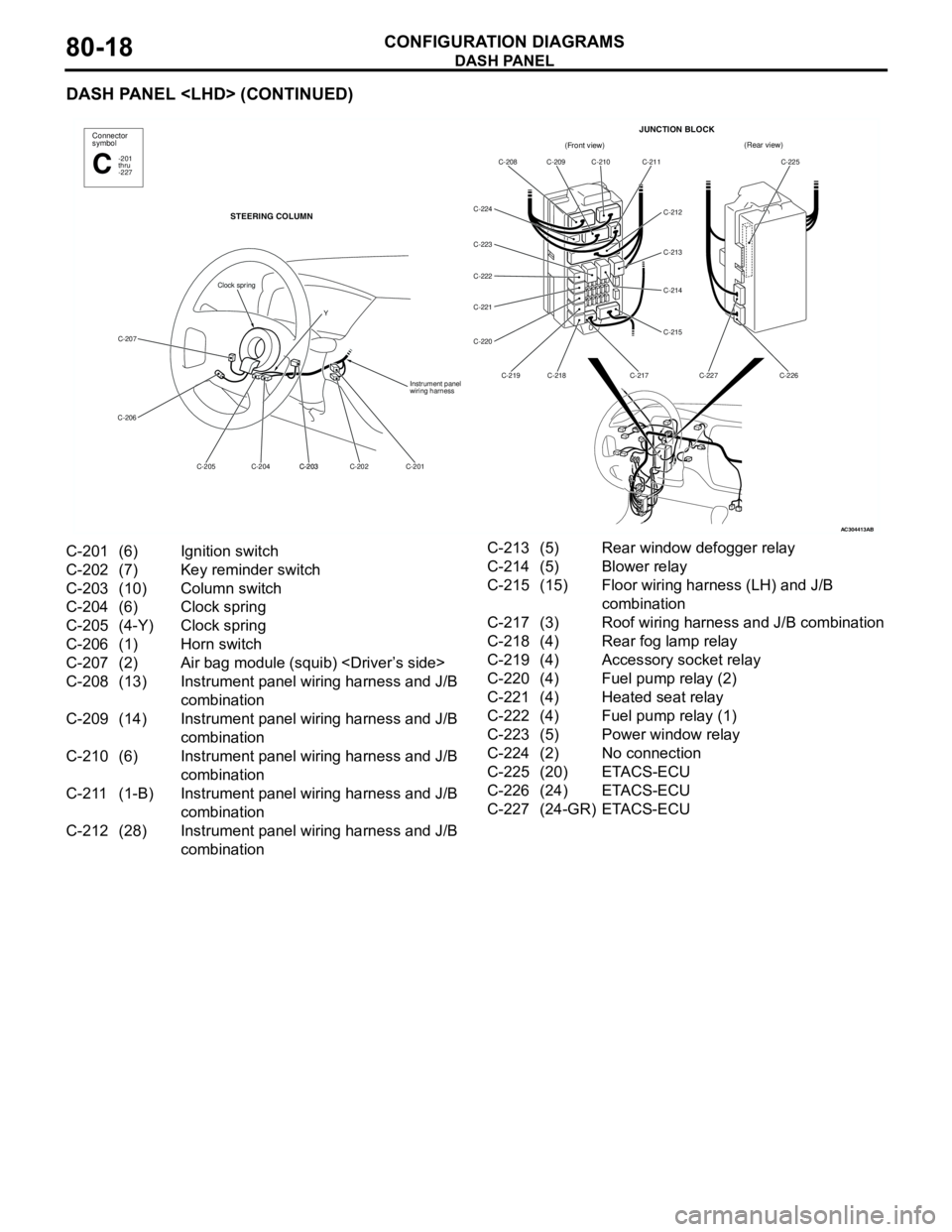
DASH PANEL
CONFIGURATION DIAGRAMS80-18
DASH PANEL
AC304413
Connector
symbol
-201
thru
-227C
STEERING COLUMN
C-207
C-206
C-201 C-202 C-203
C-203 C-204 C-205Instrument panel
wiring harness
Clock spring
Y
AB
(Front view)(Rear view)
C-208 C-209 C-210 C-211
C-212
C-213
C-214
C-215
C-217 C-218 C-219 C-220 C-221 C-222 C-223 C-224C-225
C-226 C-227
JUNCTION BLOCK
C-201 (6) Ignition switch
C-202 (7) Key reminder switch
C-203 (10) Column switch
C-204 (6) Clock spring
C-205 (4-Y) Clock spring
C-206 (1) Horn switch
C-207 (2) Air bag module (squib)
C-208 (13) Instrument panel wiring harness and J/B
combination
C-209 (14) Instrument panel wiring harness and J/B
combination
C-210 (6) Instrument panel wiring harness and J/B
combination
C-211 (1-B) Instrument panel wiring harness and J/B
combination
C-212 (28) Instrument panel wiring harness and J/B
combinationC-213 (5) Rear window defogger relay
C-214 (5) Blower relay
C-215 (15) Floor wiring harness (LH) and J/B
combination
C-217 (3) Roof wiring harness and J/B combination
C-218 (4) Rear fog lamp relay
C-219 (4) Accessory socket relay
C-220 (4) Fuel pump relay (2)
C-221 (4) Heated seat relay
C-222 (4) Fuel pump relay (1)
C-223 (5) Power window relay
C-224 (2) No connection
C-225 (20) ETACS-ECU
C-226 (24) ETACS-ECU
C-227 (24-GR) ETACS-ECU
Page 626 of 788
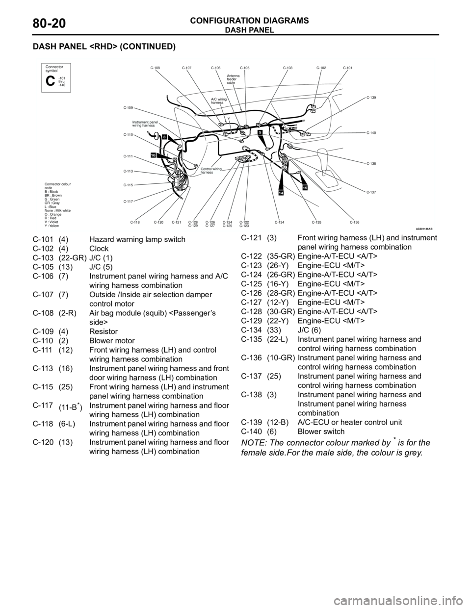
DASH PANEL
CONFIGURATION DIAGRAMS80-20
DASH PANEL
NOTE: The connector colour marked by
* is for the
female side.For the male side, the colour is grey.
AC301146
Y
16
C-105 C-106 C-107 C-108
A/C wiring
harness
C-109
C-110
C-111
C-113
C-115
C-117
Instrument panel
wiring harness
Control wiring
harness
C-118C-120
C-121
C-128
C-129C-126
C-127C-124
C-125C-122
C-123 Connector colour
code
B : Black
BR : Brown
G : Green
GR : Gray
L : Blue
None : Milk white
O : Orange
R : Red
V : Violet
Y : Yellow
3
Connector
symbol
-101
thru
-140C
Antenna
feeder
cable
AB
5
1415
C-103
C-102
C-101
C-139
C-138
C-137 C-140
C-136 C-135
C-134
C-101 (4) Hazard warning lamp switch
C-102 (4) Clock
C-103 (22-GR) J/C (1)
C-105 (13) J/C (5)
C-106 (7) Instrument panel wiring harness and A/C
wiring harness combination
C-107 (7) Outside /Inside air selection damper
control motor
C-108 (2-R) Air bag module (squib)
C-109 (4) Resistor
C-110 (2) Blower motor
C-111 (12) Front wiring harness (LH) and control
wiring harness combination
C-113 (16) Instrument panel wiring harness and front
door wiring harness (LH) combination
C-115 (25) Front wiring harness (LH) and instrument
panel wiring harness combination
C-117
(11-B
*)Instrument panel wiring harness and floor
wiring harness (LH) combination
C-118 (6-L) Instrument panel wiring harness and floor
wiring harness (LH) combination
C-120 (13) Instrument panel wiring harness and floor
wiring harness (LH) combinationC-121 (3) Front wiring harness (LH) and instrument
panel wiring harness combination
C-122 (35-GR) Engine-A/T-ECU
C-123 (26-Y) Engine-ECU
C-124 (26-GR) Engine-A/T-ECU
C-125 (16-Y) Engine-ECU
C-126 (28-GR) Engine-A/T-ECU
C-127 (12-Y) Engine-ECU
C-128 (30-GR) Engine-A/T-ECU
C-129 (22-Y) Engine-ECU
C-134 (33) J/C (6)
C-135 (22-L) Instrument panel wiring harness and
control wiring harness combination
C-136 (10-GR) Instrument panel wiring harness and
control wiring harness combination
C-137 (25) Instrument panel wiring harness and
control wiring harness combination
C-138 (3) Instrument panel wiring harness and
Instrument panel wiring harness
combination
C-139 (12-B) A/C-ECU or heater control unit
C-140 (6) Blower switch
Page 627 of 788
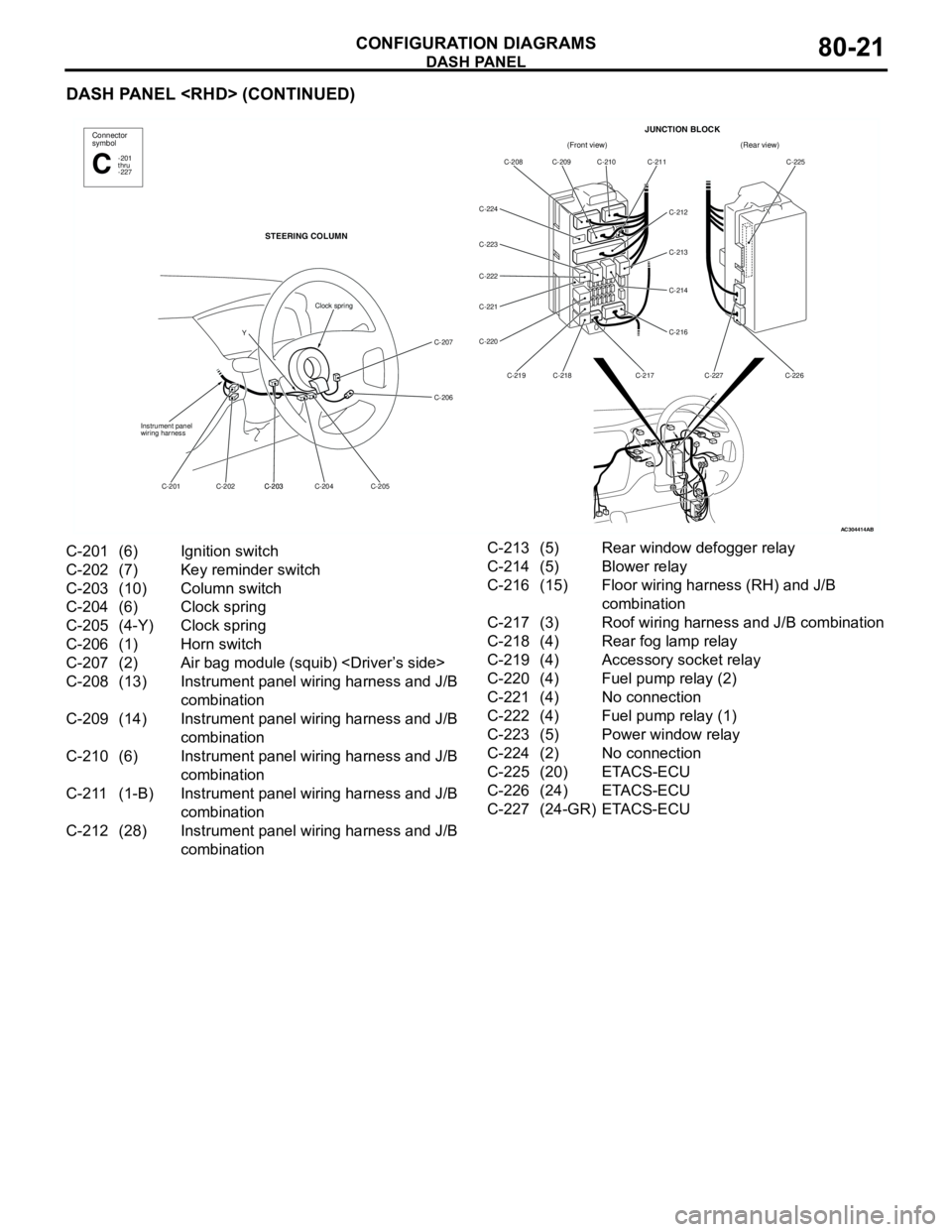
DASH PANEL
CONFIGURATION DIAGRAMS80-21
DASH PANEL
AC304414AB
(Front view)(Rear view)
C-208 C-209 C-210 C-211
C-212
C-213
C-214
C-216
C-217 C-218 C-219 C-220 C-221 C-222 C-223 C-224C-225
C-226 C-227
JUNCTION BLOCKConnector
symbol
-201
thru
-227C
STEERING COLUMN
C-207
C-206
C-205 C-204 C-203
C-203 C-202 C-201 Instrument panel
wiring harness
Clock spring
Y
C-201 (6) Ignition switch
C-202 (7) Key reminder switch
C-203 (10) Column switch
C-204 (6) Clock spring
C-205 (4-Y) Clock spring
C-206 (1) Horn switch
C-207 (2) Air bag module (squib)
C-208 (13) Instrument panel wiring harness and J/B
combination
C-209 (14) Instrument panel wiring harness and J/B
combination
C-210 (6) Instrument panel wiring harness and J/B
combination
C-211 (1-B) Instrument panel wiring harness and J/B
combination
C-212 (28) Instrument panel wiring harness and J/B
combinationC-213 (5) Rear window defogger relay
C-214 (5) Blower relay
C-216 (15) Floor wiring harness (RH) and J/B
combination
C-217 (3) Roof wiring harness and J/B combination
C-218 (4) Rear fog lamp relay
C-219 (4) Accessory socket relay
C-220 (4) Fuel pump relay (2)
C-221 (4) No connection
C-222 (4) Fuel pump relay (1)
C-223 (5) Power window relay
C-224 (2) No connection
C-225 (20) ETACS-ECU
C-226 (24) ETACS-ECU
C-227 (24-GR) ETACS-ECU
Page 628 of 788
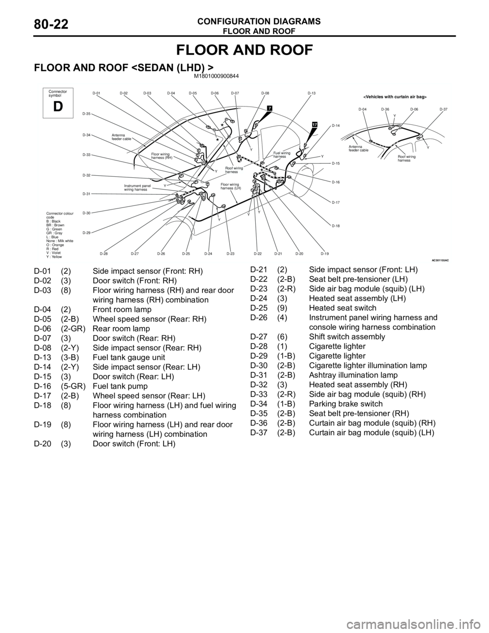
FLOOR AND ROOF
CONFIGURATION DIAGRAMS80-22
FLOOR AND ROOF
FLOOR AND ROOF
AC301155
D-06
D-07
D-05 D-04 D-03 D-02 D-01
D-35
D-34
D-33
D-32
D-31
D-30
D-29
D-25
D-28D-27 D-24
D-23 Y
Y
YFloor wiring
harness (LH) Floor wiring
harness (RH)
Instrument panel
wiring harnessConnector
symbol
D
D-26
Roof wiring
harness
Connector colour
code
B : Black
BR : Brown
G : Green
GR : Gray
L : Blue
None : Milk white
O : Orange
R : Red
V : Violet
Y : Yellow
Antenna
feeder cable
D-08
D-13
D-14
D-15
D-16
D-17
D-18
D-19 D-20
D-21 D-22Y
YFuel wiring
harness
7
17
Y
Y
AC
Y
Y D-04 D-36 D-06 D-37
Roof wiring
harness
Antenna
feeder cable
D-01 (2) Side impact sensor (Front: RH)
D-02 (3) Door switch (Front: RH)
D-03 (8) Floor wiring harness (RH) and rear door
wiring harness (RH) combination
D-04 (2) Front room lamp
D-05 (2-B) Wheel speed sensor (Rear: RH)
D-06 (2-GR) Rear room lamp
D-07 (3) Door switch (Rear: RH)
D-08 (2-Y) Side impact sensor (Rear: RH)
D-13 (3-B) Fuel tank gauge unit
D-14 (2-Y) Side impact sensor (Rear: LH)
D-15 (3) Door switch (Rear: LH)
D-16 (5-GR) Fuel tank pump
D-17 (2-B) Wheel speed sensor (Rear: LH)
D-18 (8) Floor wiring harness (LH) and fuel wiring
harness combination
D-19 (8) Floor wiring harness (LH) and rear door
wiring harness (LH) combination
D-20 (3) Door switch (Front: LH)D-21 (2) Side impact sensor (Front: LH)
D-22 (2-B) Seat belt pre-tensioner (LH)
D-23 (2-R) Side air bag module (squib) (LH)
D-24 (3) Heated seat assembly (LH)
D-25 (9) Heated seat switch
D-26 (4) Instrument panel wiring harness and
console wiring harness combination
D-27 (6) Shift switch assembly
D-28 (1) Cigarette lighter
D-29 (1-B) Cigarette lighter
D-30 (2-B) Cigarette lighter illumination lamp
D-31 (2-B) Ashtray illumination lamp
D-32 (3) Heated seat assembly (RH)
D-33 (2-R) Side air bag module (squib) (RH)
D-34 (1-B) Parking brake switch
D-35 (2-B) Seat belt pre-tensioner (RH)
D-36 (2-B) Curtain air bag module (squib) (RH)
D-37 (2-B) Curtain air bag module (squib) (LH)
Page 629 of 788
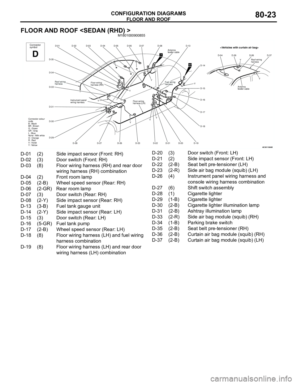
FLOOR AND ROOF
CONFIGURATION DIAGRAMS80-23
FLOOR AND ROOF
AC301158
D-06
D-07
D-05 D-04 D-03 D-02 D-01
D-35
D-34
D-33
D-31
D-30
D-29
D-28D-27
D-23 Y
Y
YFloor wiring
harness (LH) Floor wiring
harness (RH)
Instrument panel
wiring harnessConnector
symbol
D
D-26
Roof wiring
harness
Connector colour
code
B : Black
BR : Brown
G : Green
GR : Gray
L : Blue
None : Milk white
O : Orange
R : Red
V : Violet
Y : Yellow
D-08
D-13
D-14
D-15
D-16
D-17
D-18
D-19 D-20
D-21 D-22Y
YFuel wiring
harness
7
17
Y
Y
Antenna
feeder cable
AB
Y
Y D-04 D-36 D-06 D-37Roof wiring
harness
Antenna
feeder cable
D-01 (2) Side impact sensor (Front: RH)
D-02 (3) Door switch (Front: RH)
D-03 (8) Floor wiring harness (RH) and rear door
wiring harness (RH) combination
D-04 (2) Front room lamp
D-05 (2-B) Wheel speed sensor (Rear: RH)
D-06 (2-GR) Rear room lamp
D-07 (3) Door switch (Rear: RH)
D-08 (2-Y) Side impact sensor (Rear: RH)
D-13 (3-B) Fuel tank gauge unit
D-14 (2-Y) Side impact sensor (Rear: LH)
D-15 (3) Door switch (Rear: LH)
D-16 (5-GR) Fuel tank pump
D-17 (2-B) Wheel speed sensor (Rear: LH)
D-18 (8) Floor wiring harness (LH) and fuel wiring
harness combination
D-19 (8) Floor wiring harness (LH) and rear door
wiring harness (LH) combinationD-20 (3) Door switch (Front: LH)
D-21 (2) Side impact sensor (Front: LH)
D-22 (2-B) Seat belt pre-tensioner (LH)
D-23 (2-R) Side air bag module (squib) (LH)
D-26 (4) Instrument panel wiring harness and
console wiring harness combination
D-27 (6) Shift switch assembly
D-28 (1) Cigarette lighter
D-29 (1-B) Cigarette lighter
D-30 (2-B) Cigarette lighter illumination lamp
D-31 (2-B) Ashtray illumination lamp
D-33 (2-R) Side air bag module (squib) (RH)
D-34 (1-B) Parking brake switch
D-35 (2-B) Seat belt pre-tensioner (RH)
D-36 (2-B) Curtain air bag module (squib) (RH)
D-37 (2-B) Curtain air bag module (squib) (LH)
Page 630 of 788
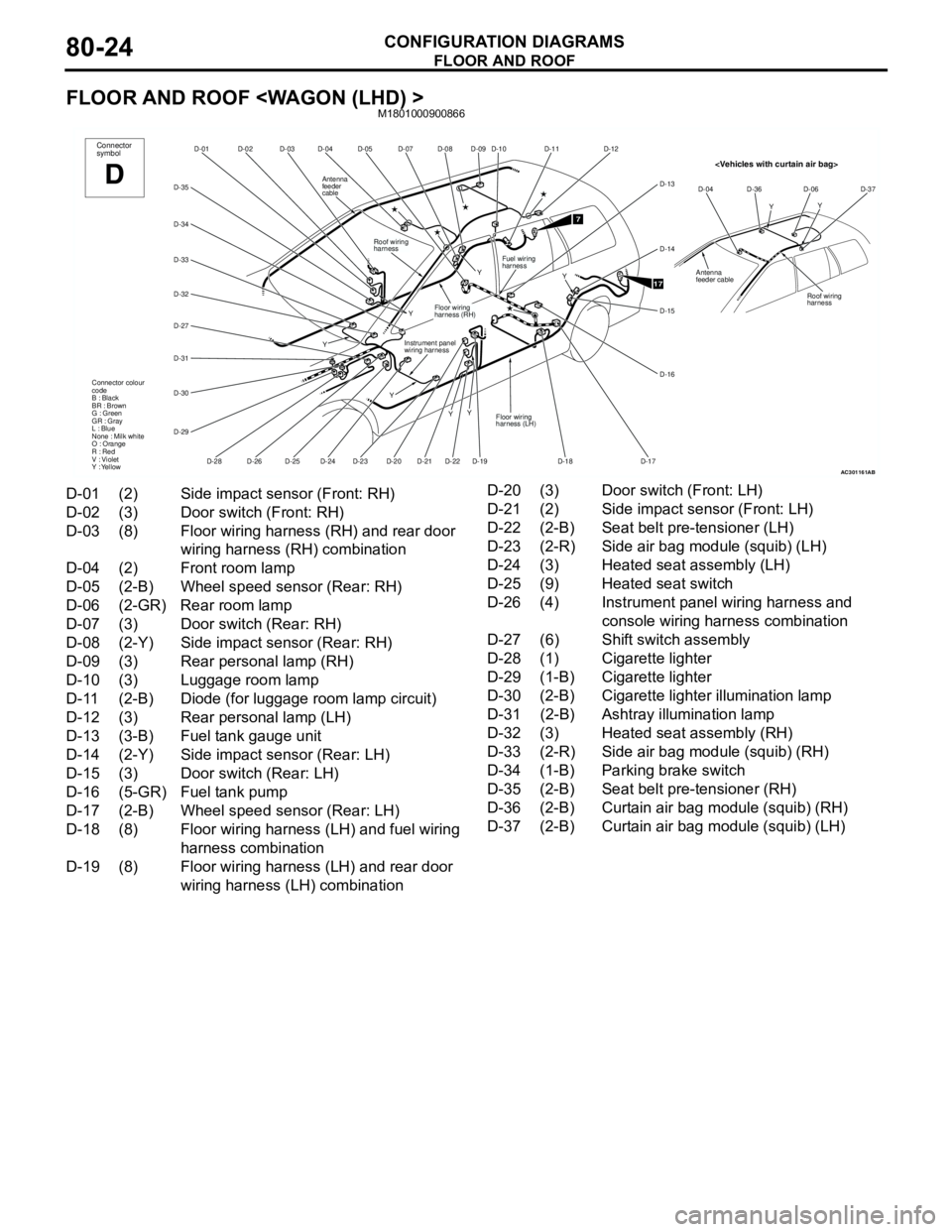
FLOOR AND ROOF
CONFIGURATION DIAGRAMS80-24
FLOOR AND ROOF
AC301161
D-07
D-08 D-05
D-04 D-03 D-02
D-01
D-35
D-34
D-33
D-31
D-30
D-29
D-28
D-24D-19 Y
Y
YConnector
symbol
D
D-20
Roof wiring
harness
Connector colour
code
B : Black
BR : Brown
G : Green
GR : Gray
L : Blue
None : Milk white
O : Orange
R : Red
V : Violet
Y : Yellow
D-09
D-22D-21D-23D-25D-26
D-32
D-27
Y
YInstrument panel
wiring harness
Floor wiring
harness (RH)
Y
Antenna
feeder
cable
D-10
D-12
D-14
D-15
D-16
D-17 D-18
Fuel wiring
harness
7
17Y
D-11
D-13
Floor wiring
harness (LH)
AB
YY D-04 D-36 D-06 D-37
Roof wiring
harness
Antenna
feeder cable
D-01 (2) Side impact sensor (Front: RH)
D-02 (3) Door switch (Front: RH)
D-03 (8) Floor wiring harness (RH) and rear door
wiring harness (RH) combination
D-04 (2) Front room lamp
D-05 (2-B) Wheel speed sensor (Rear: RH)
D-06 (2-GR) Rear room lamp
D-07 (3) Door switch (Rear: RH)
D-08 (2-Y) Side impact sensor (Rear: RH)
D-09 (3) Rear personal lamp (RH)
D-10 (3) Luggage room lamp
D-11 (2-B) Diode (for luggage room lamp circuit)
D-12 (3) Rear personal lamp (LH)
D-13 (3-B) Fuel tank gauge unit
D-14 (2-Y) Side impact sensor (Rear: LH)
D-15 (3) Door switch (Rear: LH)
D-16 (5-GR) Fuel tank pump
D-17 (2-B) Wheel speed sensor (Rear: LH)
D-18 (8) Floor wiring harness (LH) and fuel wiring
harness combination
D-19 (8) Floor wiring harness (LH) and rear door
wiring harness (LH) combinationD-20 (3) Door switch (Front: LH)
D-21 (2) Side impact sensor (Front: LH)
D-22 (2-B) Seat belt pre-tensioner (LH)
D-23 (2-R) Side air bag module (squib) (LH)
D-24 (3) Heated seat assembly (LH)
D-25 (9) Heated seat switch
D-26 (4) Instrument panel wiring harness and
console wiring harness combination
D-27 (6) Shift switch assembly
D-28 (1) Cigarette lighter
D-29 (1-B) Cigarette lighter
D-30 (2-B) Cigarette lighter illumination lamp
D-31 (2-B) Ashtray illumination lamp
D-32 (3) Heated seat assembly (RH)
D-33 (2-R) Side air bag module (squib) (RH)
D-34 (1-B) Parking brake switch
D-35 (2-B) Seat belt pre-tensioner (RH)
D-36 (2-B) Curtain air bag module (squib) (RH)
D-37 (2-B) Curtain air bag module (squib) (LH)
Page 631 of 788
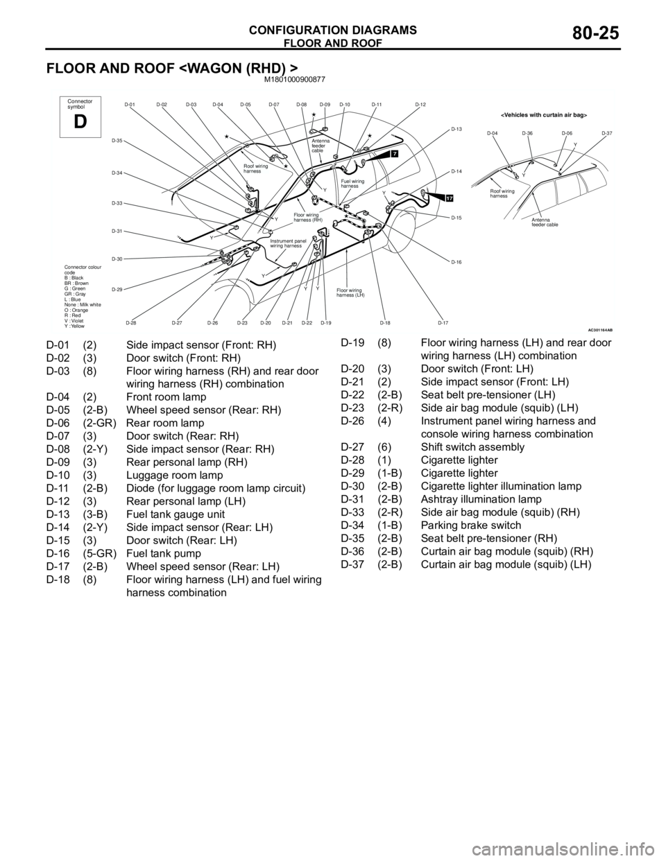
FLOOR AND ROOF
CONFIGURATION DIAGRAMS80-25
FLOOR AND ROOF
AC301164
D-07
D-08 D-05
D-04 D-03 D-02
D-01
D-35
D-34
D-33
D-31
D-30
D-29
D-28D-19 Y
Y
YConnector
symbol
D
D-20
Roof wiring
harness
Connector colour
code
B : Black
BR : Brown
G : Green
GR : Gray
L : Blue
None : Milk white
O : Orange
R : Red
V : Violet
Y : Yellow
D-09
D-22D-21D-23D-26D-27Y
Y
Instrument panel
wiring harness
Floor wiring
harness (RH)
Y
Antenna
feeder
cable
D-10
D-12
D-14
D-15
D-16
D-17 D-18
Fuel wiring
harness
7
17Y
D-11
D-13
Floor wiring
harness (LH)
AB
YY D-04 D-36 D-06 D-37
Roof wiring
harness
Antenna
feeder cable
D-01 (2) Side impact sensor (Front: RH)
D-02 (3) Door switch (Front: RH)
D-03 (8) Floor wiring harness (RH) and rear door
wiring harness (RH) combination
D-04 (2) Front room lamp
D-05 (2-B) Wheel speed sensor (Rear: RH)
D-06 (2-GR) Rear room lamp
D-07 (3) Door switch (Rear: RH)
D-08 (2-Y) Side impact sensor (Rear: RH)
D-09 (3) Rear personal lamp (RH)
D-10 (3) Luggage room lamp
D-11 (2-B) Diode (for luggage room lamp circuit)
D-12 (3) Rear personal lamp (LH)
D-13 (3-B) Fuel tank gauge unit
D-14 (2-Y) Side impact sensor (Rear: LH)
D-15 (3) Door switch (Rear: LH)
D-16 (5-GR) Fuel tank pump
D-17 (2-B) Wheel speed sensor (Rear: LH)
D-18 (8) Floor wiring harness (LH) and fuel wiring
harness combinationD-19 (8) Floor wiring harness (LH) and rear door
wiring harness (LH) combination
D-20 (3) Door switch (Front: LH)
D-21 (2) Side impact sensor (Front: LH)
D-22 (2-B) Seat belt pre-tensioner (LH)
D-23 (2-R) Side air bag module (squib) (LH)
D-26 (4) Instrument panel wiring harness and
console wiring harness combination
D-27 (6) Shift switch assembly
D-28 (1) Cigarette lighter
D-29 (1-B) Cigarette lighter
D-30 (2-B) Cigarette lighter illumination lamp
D-31 (2-B) Ashtray illumination lamp
D-33 (2-R) Side air bag module (squib) (RH)
D-34 (1-B) Parking brake switch
D-35 (2-B) Seat belt pre-tensioner (RH)
D-36 (2-B) Curtain air bag module (squib) (RH)
D-37 (2-B) Curtain air bag module (squib) (LH)
Page 641 of 788

90-3
CENTRAL DOOR LOCKING SYSTEM
CENTRAL DOOR LOCKING SYSTEM
HEATER
HEATER
MANUAL AIR CONDITIONER
MANUAL AIR CONDITIONER
WINDSHIELD WIPER AND WASHER
WINDSHIELD WIPER AND WASHER
RHD> . . . . . . . . . . . . . . . . . . . . . . . . .90-121
REAR WIPER AND WASHER
REAR WIPER AND WASHER
REAR WINDOW DEFOGGER AND
DOOR MIRROR HEATER
REAR WINDOW DEFOGGER AND
DOOR MIRROR HEATER
REMOTE CONTROLLED MIRROR
HEADLAMP WASHER . . . . . . . . . . . .90-131
SPARE CONNECTOR (FOR AUDIO)
SPARE CONNECTOR (FOR AUDIO)
CLOCK . . . . . . . . . . . . . . . . . . . . . . . .90-134
CIGARETTE LIGHTER AND ASHTRAY
ILLUMINATION LAMP . . . . . . . . . . . .90-135
ACCESSORY SOCKET . . . . . . . . . . .90-136
IMMOBILIZER SYSTEM
IMMOBILIZER SYSTEM
ABS
ABS
HEATED SEAT . . . . . . . . . . . . . . . . . .90-143
RHEOSTAT
RHEOSTAT
SUPPLEMENTAL RESTRAINT SYSTEM
(SRS)
SUPPLEMENTAL RESTRAINT SYSTEM
(SRS)
SPARE CONNECTOR (FOR FRONT
FOG LAMP) . . . . . . . . . . . . . . . . . . . .90-150
Page 644 of 788
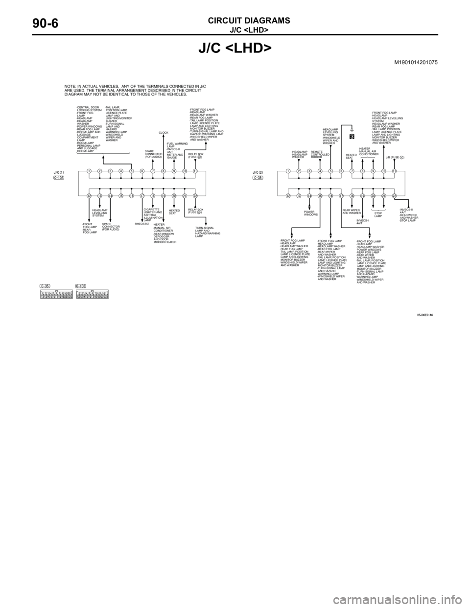
J/C
CIRCUIT DIAGRAMS90-6
J/C
M1901014201075
NOTE: IN ACTUAL VEHICLES, ANY OF THE TERMINALS CONNECTED IN J/C
ARE USED. THE TERMINAL ARRANGEMENT DESCRIBED IN THE CIRCUIT
DIAGRAM MAY NOT BE IDENTICAL TO THOSE OF THE VEHICLES.
·CENTRAL DOOR
LOCKING SYSTEM
·FRONT FOG
LAMP
·HEADLAMP
·HEADLAMP
WASHER
·POWER WINDOWS
·REAR FOG LAMP
·ROOM LAMP AND
LUGGAGE
COMPARTMENT
LAMP
·ROOM LAMP
PERSONAL LAMP
AND LUGGAGE
ROOM LAMP ·TAIL LAMP,
POSITION LAMP,
LICENCE PLATE
LAMP AND
LIGHTING MONITOR
BUZZER
·TURN-SIGNAL
LAMP AND
HAZARD
WARNING LAMP
·WINDSHIELD
WIPER AND
WASHER
RELAY BOX
(FUSE )·FRONT FOG LAMP
·HEADLAMP
·HEADLAMP WASHER
·REAR FOG LAMP
·TAIL LAMP, POSITION
LAMP, LICENCE PLATE
LAMP AND LIGHTING
MONITOR BUZZER
·TURN-SIGNAL LAMP AND
HAZARD WARNING LAMP
·WINDSHIELD WIPER
AND WASHER
SPARE
CONNECTOR
(FOR AUDIO)CLOCK
·FUEL WARNING
LAMP
·INVECS-II
4A/T
·METER AND
GAUGE
RELAY BOX
(FUSE )
TURN-SIGNAL
LAMP AND
HAZARD WARNING
LAMP HEATED
SEAT
·HEATER CIGARETTE
LIGHTER AND
ASHTRAY
ILLUMINATION
LAMP
RHEOSTAT
SPARE
CONNECTOR
(FOR AUDIO) HEADLAMP
LEVELLING
SYSTEM
·FRONT
FOG LAMP
·REAR
FOG LAMP
20
22
·REAR WINDOW
DEFOGGER
AND DOOR
MIRROR HEATER ·MANUAL AIR
CONDITIONERREAR WIPER
AND WASHER
·FRONT FOG LAMP
·HEADLAMP
·HEADLAMP WASHER
·REAR FOG LAMP
·TAIL LAMP, POSITION
LAMP, LICENCE PLATE
LAMP AND LIGHTING
MONITOR BUZZER
·WINDSHIELD WIPER
AND WASHERINVECS-II
4A/T POWER
WINDOWSSTOP
LAMP·INVECS-II
4A/T
·REAR WIPER
AND WASHER
·STOP LAMP
·FRONT FOG LAMP
·HEADLAMP
·HEADLAMP WASHER
·REAR FOG LAMP
·REAR WIPER
AND WASHER
·TAIL LAMP, POSITION
LAMP, LICENCE PLATE
LAMP AND LIGHTING
MONITOR BUZZER
·TURN-SIGNAL LAMP
AND HAZARD
WARNING LAMP
·WINDSHIELD WIPER
AND WASHER·FRONT FOG LAMP
·HEADLAMP
·HEADLAMP WASHER
·POWER WINDOWS
·REAR FOG LAMP
·REAR WIPER
AND WASHER
·TAIL LAMP, POSITION
LAMP, LICENCE PLATE
LAMP AND LIGHTING
MONITOR BUZZER
·TURN-SIGNAL LAMP
AND HAZARD
WARNING LAMP
·WINDSHIELD WIPER
AND WASHER·FRONT FOG LAMP
·HEADLAMP
·HEADLAMP LEVELLING
SYSTEM
·HEADLAMP WASHER
·REAR FOG LAMP
·TAIL LAMP, POSITION
LAMP, LICENCE PLATE
LAMP AND LIGHTING
MONITOR BUZZER
·WINDSHIELD WIPER
AND WASHER
·HEATER
·MANUAL AIR
CONDITIONER
J/B (FUSE ) HEATED
SEAT ·HEADLAMP
LEVELLING
SYSTEM
·WINDSHIELD
WIPER AND
WASHER
REMOTE
CONTROLLED
MIRROR ·HEADLAMP
·HEADLAMP
WASHER
5