engine MITSUBISHI LANCER 2005 Workshop Manual
[x] Cancel search | Manufacturer: MITSUBISHI, Model Year: 2005, Model line: LANCER, Model: MITSUBISHI LANCER 2005Pages: 788, PDF Size: 45.98 MB
Page 573 of 788
EVAPORATOR ASSEMBLY
HEATER, AIR CONDITIONER AND VENTILATION55-89
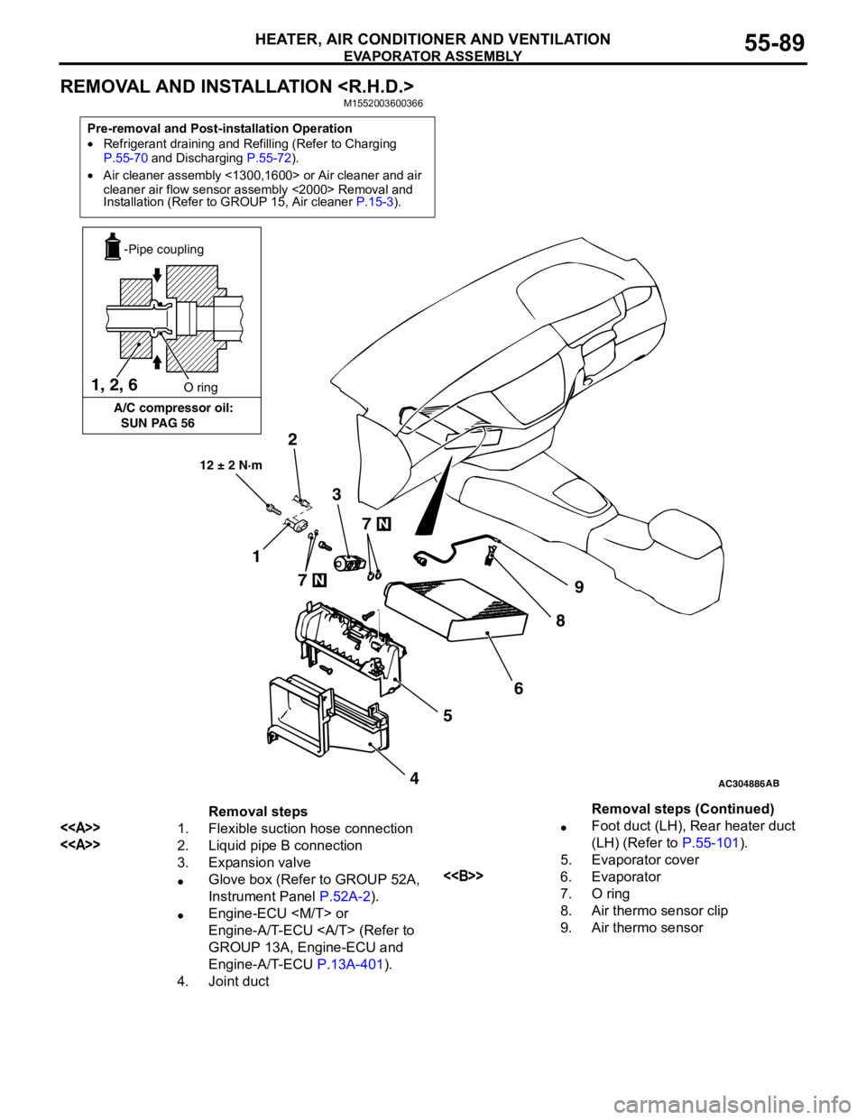
REMOVAL AND INSTALLATION
Pre-removal and Post-installation Operation
•Refrigerant draining and Refilling (Refer to Charging
P.55-70 and Discharging P.55-72).
•Air cleaner assembly <1300,1600> or Air cleaner and air
cleaner air flow sensor assembly <2000> Removal and
Installation (Refer to GROUP 15, Air cleaner P.15-3).
AC304886AB
12 ± 2 N·m
7
7
2
1
9
8
6
5
4 3 1, 2, 6
A/C compressor oil:
SUN PAG 56O ring
-Pipe coupling
Removal steps
<>1. Flexible suction hose connection
<>2. Liquid pipe B connection
3. Expansion valve
•Glove box (Refer to GROUP 52A,
Instrument Panel P.52A-2).
•Engine-ECU
Engine-A/T-ECU (Refer to
GROUP 13A, Engine-ECU and
Engine-A/T-ECU P.13A-401).
4. Joint duct•Foot duct (LH), Rear heater duct
(LH) (Refer to P.55-101).
5. Evaporator cover
<>6. Evaporator
7. O ring
8. Air thermo sensor clip
9. Air thermo sensorRemoval steps (Continued)
Page 579 of 788
COMPRESSOR ASSEMBLY AND TENSION PULLEY
HEATER, AIR CONDITIONER AND VENTILATION55-95
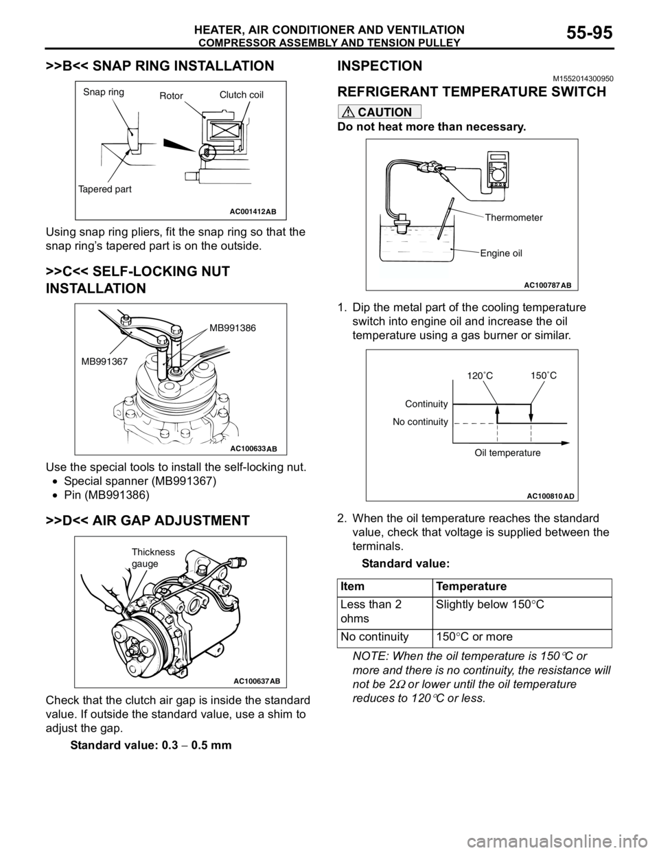
>>B<< SNAP RING INSTALLATION
Using snap ring pliers, fit the snap ring so that the
snap ring’s tapered part is on the outside.
>>C<< SELF-LOCKING NUT
INSTALLATION
Use the special tools to install the self-locking nut.
•Special spanner (MB991367)
•Pin (MB991386)
>>D<< AIR GAP ADJUSTMENT
Check that the clutch air gap is inside the standard
value. If outside the standard value, use a shim to
adjust the gap.
Standard value: 0.3 − 0.5 mm
INSPECTIONM1552014300950
REFRIGERANT TEMPERATURE SWITCH
CAUTION
Do not heat more than necessary.
1. Dip the metal part of the cooling temperature
switch into engine oil and increase the oil
temperature using a gas burner or similar.
2. When the oil temperature reaches the standard
value, check that voltage is supplied between the
terminals.
Standard value:
NOTE: When the oil temperature is 150
°C or
more and there is no continuity, the resistance will
not be 2
Ω or lower until the oil temperature
reduces to 120
°C or less.
AC001412
Snap ring
RotorClutch coil
Tapered part
AB
AC100633AB
MB991386
MB991367
AC100637AB
Thickness
gauge
Item Temperature
Less than 2
ohmsSlightly below 150°C
No continuity 150°C or more
AC100787
Thermometer
Engine oil
AB
AC100810
Continuity
No continuity
Oil temperature
AD
120˚C150˚C
Page 588 of 788
ECU
COMPONENT LOCATIONS70-2
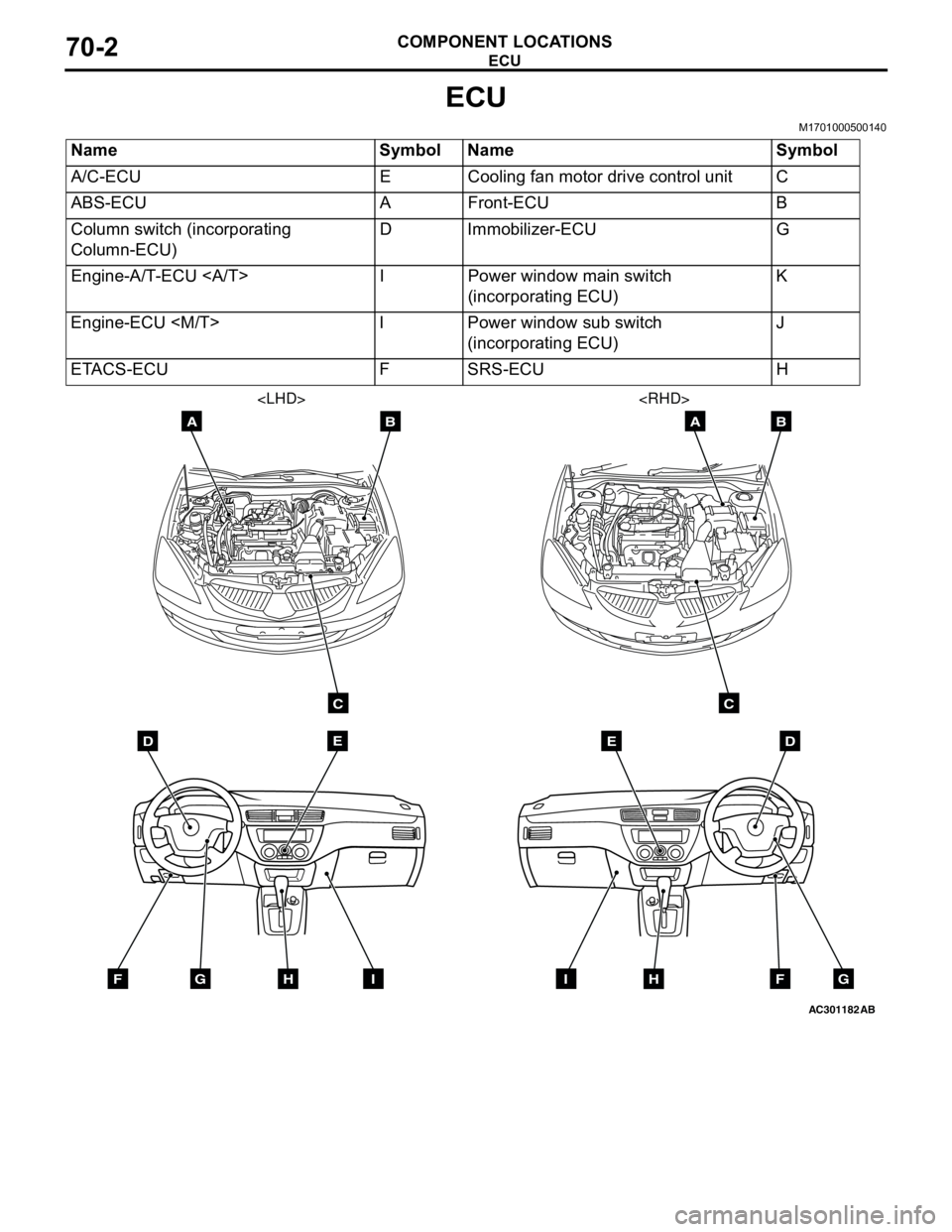
ECU
M1701000500140
Name Symbol Name Symbol
A/C-ECU E Cooling fan motor drive control unit C
ABS-ECU A Front-ECU B
Column switch (incorporating
Column-ECU)D Immobilizer-ECU G
Engine-A/T-ECU I Power window main switch
(incorporating ECU)K
Engine-ECU
(incorporating ECU)J
ETACS-ECU F SRS-ECU H
AC301182
DE
AB
C
FGHI
AB
DE
AB
C
FGHI
Page 590 of 788
ECU
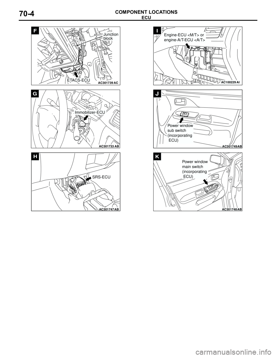
COMPONENT LOCATIONS70-4
AC301739AC
F
ETACS-ECU
Junction
block
AC301733
AB
Immobilizer-ECU
G
AC301747AB
SRS-ECU
H
AC100229AI
Engine-ECU
engine-A/T-ECU I
AC301749AB
Power window
sub switch
(incorporating
ECU)
J
AC301748AB
Power window
main switch
(incorporating
ECU)
K
Page 591 of 788
RELAY
COMPONENT LOCATIONS70-5
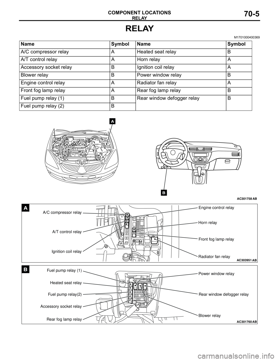
RELAY
M1701000400369
Name Symbol Name Symbol
A/C compressor relay A Heated seat relay B
A/T control relay A Horn relay A
Accessory socket relay B Ignition coil relay A
Blower relay B Power window relay B
Engine control relay A Radiator fan relay A
Front fog lamp relay A Rear fog lamp relay B
Fuel pump relay (1) B Rear window defogger relay B
Fuel pump relay (2) B
AC301758AB
A
B
AC303951AB
A/C compressor relayEngine control relay
Horn relay
Front fog lamp relay
Radiator fan relay A/T control relay
Ignition coil relayA
AC301760
Fuel pump relay (1)
Power window relay
Rear window defogger relay
Blower relay Heated seat relay
Fuel pump relay(2)
Accessory socket relay
Rear fog lamp relayAB
B
Page 592 of 788
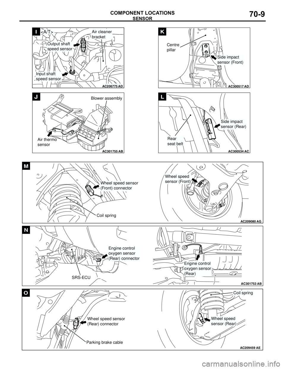
SENSOR
COMPONENT LOCATIONS70-6
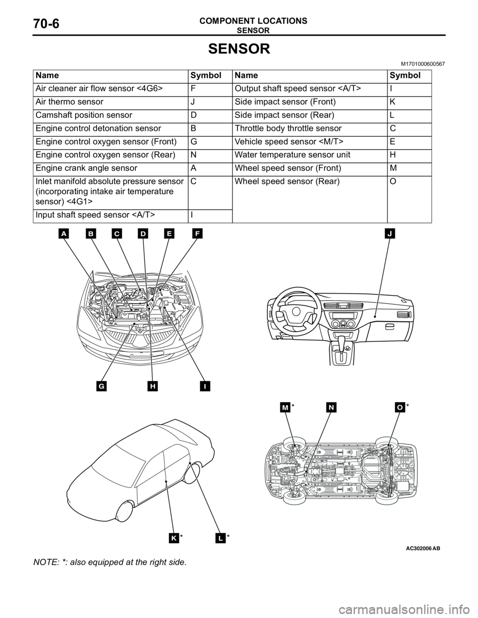
SENSOR
M1701000600567
NOTE: *: also equipped at the right side.Name Symbol Name Symbol
Air cleaner air flow sensor <4G6> F Output shaft speed sensor I
Air thermo sensor J Side impact sensor (Front) K
Camshaft position sensor D Side impact sensor (Rear) L
Engine control detonation sensor B Throttle body throttle sensor C
Engine control oxygen sensor (Front) G Vehicle speed sensor
Engine control oxygen sensor (Rear) N Water temperature sensor unit H
Engine crank angle sensor A Wheel speed sensor (Front) M
Inlet manifold absolute pressure sensor
(incorporating intake air temperature
sensor) <4G1>C Wheel speed sensor (Rear) O
Input shaft speed sensor I
AC302006AB
BDCFEA
GHI
J
KL
MNO
*
***
Page 593 of 788
SENSOR
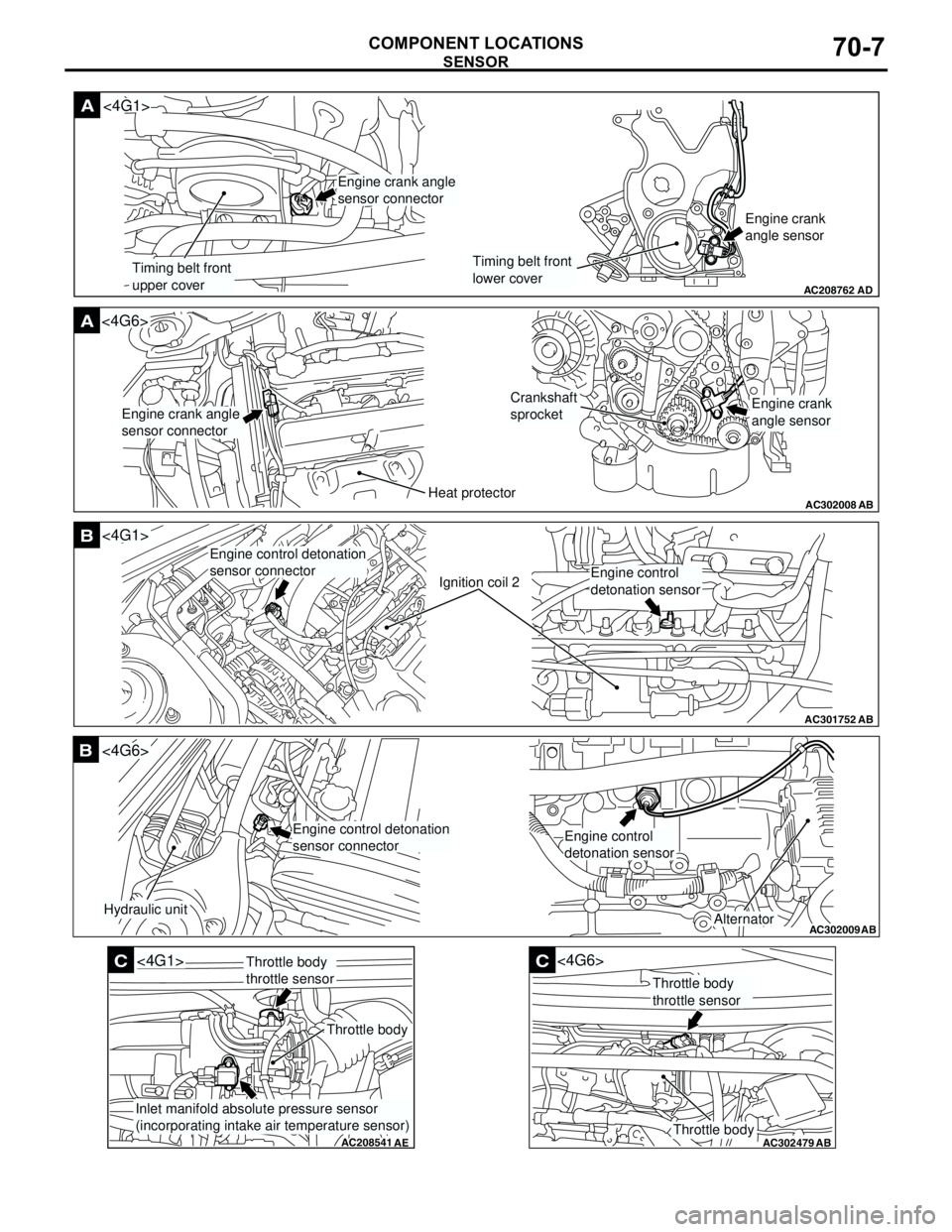
COMPONENT LOCATIONS70-7
AC208762
A
AD
Timing belt front
upper coverTiming belt front
lower coverEngine crank
angle sensor
<4G1>
Engine crank angle
sensor connector
AC302008
A<4G6>
ABHeat protector
Crankshaft
sprocket
Engine crank angle
sensor connectorEngine crank
angle sensor
AC301752
B
AB
Ignition coil 2
<4G1>
Engine control detonation
sensor connector
Engine control
detonation sensor
AC302009
B
AB
Hydraulic unit
<4G6>
Alternator
Engine control detonation
sensor connectorEngine control
detonation sensor
AC208541
C
AE
<4G1>
Throttle body
Throttle body
throttle sensor
Inlet manifold absolute pressure sensor
(incorporating intake air temperature sensor)
AC302479
AB
C
Throttle body
<4G6>
Throttle body
throttle sensor
Page 594 of 788
SENSOR
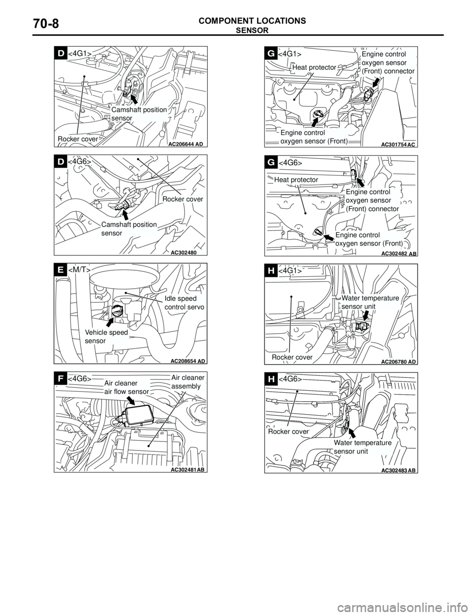
COMPONENT LOCATIONS70-8
AC206644
AD
Camshaft position
sensor
D<4G1>
Rocker cover
AC302480AB
D
Camshaft position
sensor
Rocker cover
<4G6>
AC208654
AD
E
Vehicle speed
sensor
Idle speed
control servo
AC302481AB
FAir cleaner
assembly<4G6>Air cleaner
air flow sensor
AB
AC301754
G<4G1>
AC
Heat protector
Engine control
oxygen sensor (Front)
Engine control
oxygen sensor
(Front) connector
AC302482
G
AB
Heat protector
<4G6>
Engine control
oxygen sensor
(Front) connector
Engine control
oxygen sensor (Front)
AC206780AD
H
Rocker cover
<4G1>
Water temperature
sensor unit
AC302483AC302483
<4G6>H
AB
Rocker cover
Water temperature
sensor unit
Page 595 of 788
Page 596 of 788
FUSIBLE LINK AND FUSE
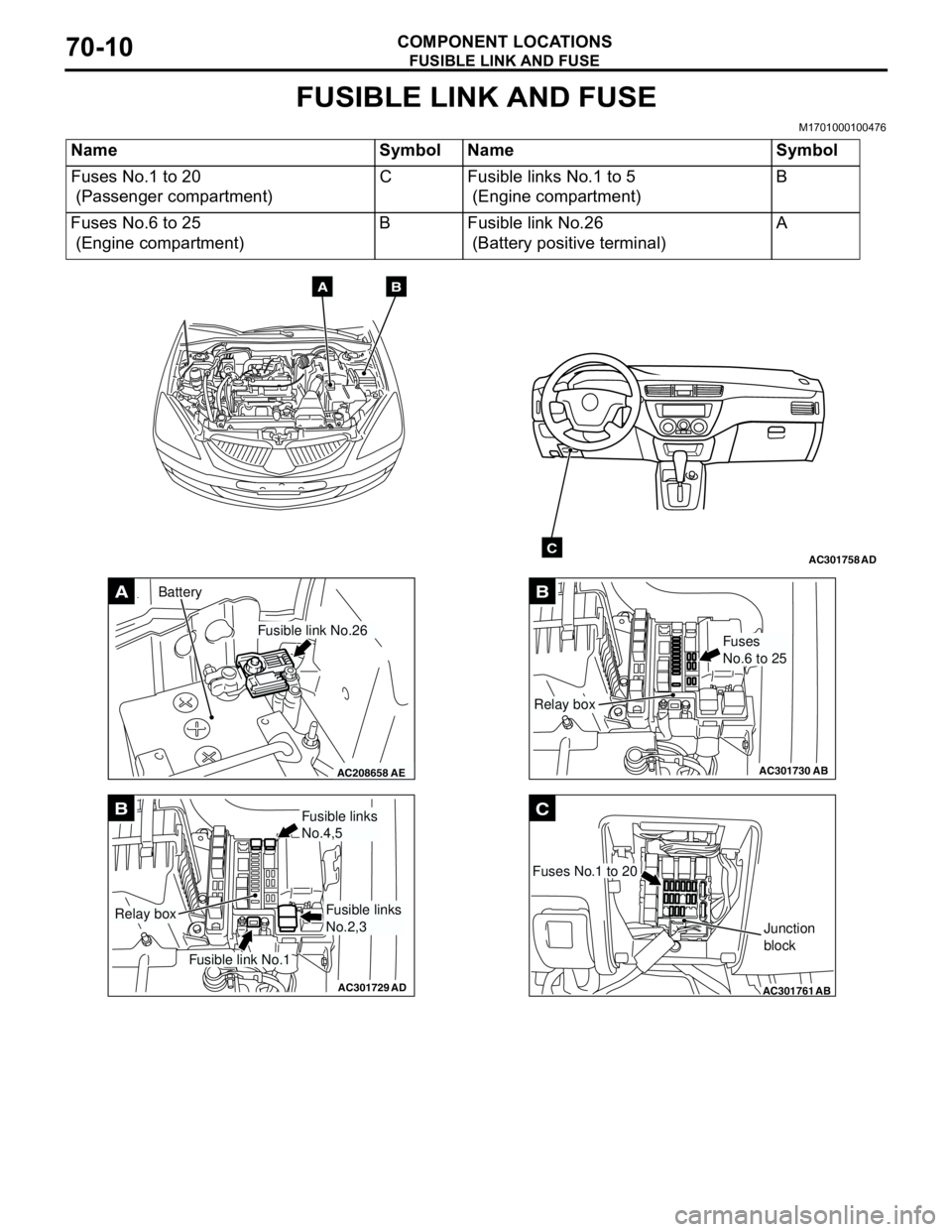
COMPONENT LOCATIONS70-10
FUSIBLE LINK AND FUSE
M1701000100476
Name Symbol Name Symbol
Fuses No.1 to 20
(Passenger compartment)C Fusible links No.1 to 5
(Engine compartment)B
Fuses No.6 to 25
(Engine compartment)B Fusible link No.26
(Battery positive terminal)A
AC301758AD
AB
C
AC208658AE
A
Fusible link No.26
Battery
AC301729AD
B
Fusible link No.1
Relay box
Fusible links
No.4,5
Fusible links
No.2,3
AC301730
B
AB
Fuses
No.6 to 25
Relay box
AC301761
C
AB
Fuses No.1 to 20
Junction
block