Side MITSUBISHI LANCER 2005 Workshop Manual
[x] Cancel search | Manufacturer: MITSUBISHI, Model Year: 2005, Model line: LANCER, Model: MITSUBISHI LANCER 2005Pages: 788, PDF Size: 45.98 MB
Page 568 of 788
HEATER UNIT, HEATER CORE, BLOWER ASSEMBLY AND EVAPORATOR UNIT
HEATER, AIR CONDITIONER AND VENTILATION55-84
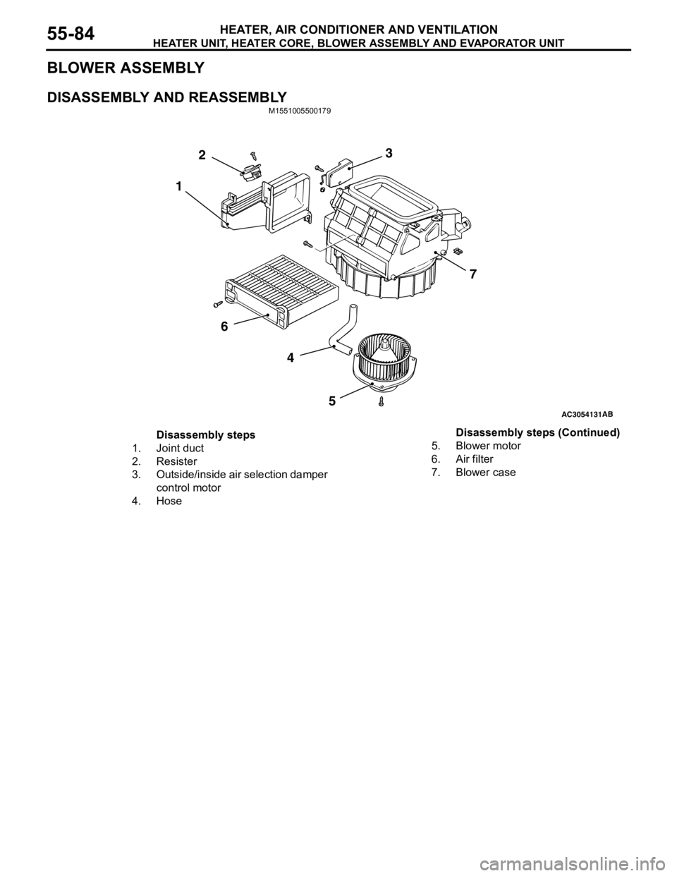
BLOWER ASSEMBLY
DISASSEMBLY AND REASSEMBLYM1551005500179
AC3054131AB
3
4
57
6
12
Disassembly steps
1. Joint duct
2. Resister
3. Outside/inside air selection damper
control motor
4. Hose5. Blower motor
6. Air filter
7. Blower caseDisassembly steps (Continued)
Page 569 of 788
BLOWERMOTOR, RESISTOR AND OUTSIDE/ INSIDE AIR SELECTION DAMPER CONTROL MOTOR
HEATER, AIR CONDITIONER AND VENTILATION55-85
BLOWERMOTOR, RESISTOR AND OUTSIDE/
INSIDE AIR SELECTION DAMPER CONTROL MOTOR
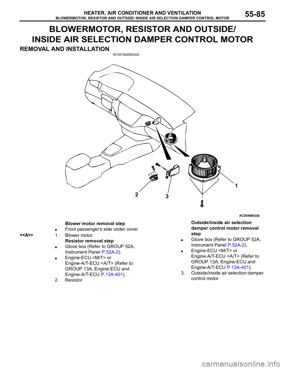
REMOVAL AND INSTALLATION
M1551002800320
AC304885AB
2
31
Blower motor removal step
•Front passenger's side under cover
<>1. Blower motor
Resistor removal step
•Glove box (Refer to GROUP 52A,
Instrument Panel P.52A-2).
•Engine-ECU
Engine-A/T-ECU (Refer to
GROUP 13A, Engine-ECU and
Engine-A/T-ECU P.13A-401).
2. ResistorOutside/inside air selection
damper control motor removal
step
•Glove box (Refer to GROUP 52A,
Instrument Panel P.52A-2).
•Engine-ECU
Engine-A/T-ECU (Refer to
GROUP 13A, Engine-ECU and
Engine-A/T-ECU P.13A-401).
3. Outside/inside air selection damper
control motor
Page 570 of 788
BLOWERMOTOR, RESISTOR AND OUTSIDE/ INSIDE AIR SELECTION DAMPER CONTROL MOTOR
HEATER, AIR CONDITIONER AND VENTILATION55-86
REMOVAL SERVICE POINT
<> BLOWER MOTOR REMOVAL
NOTE:
Use of commercially available offset screw driver is
recommended.
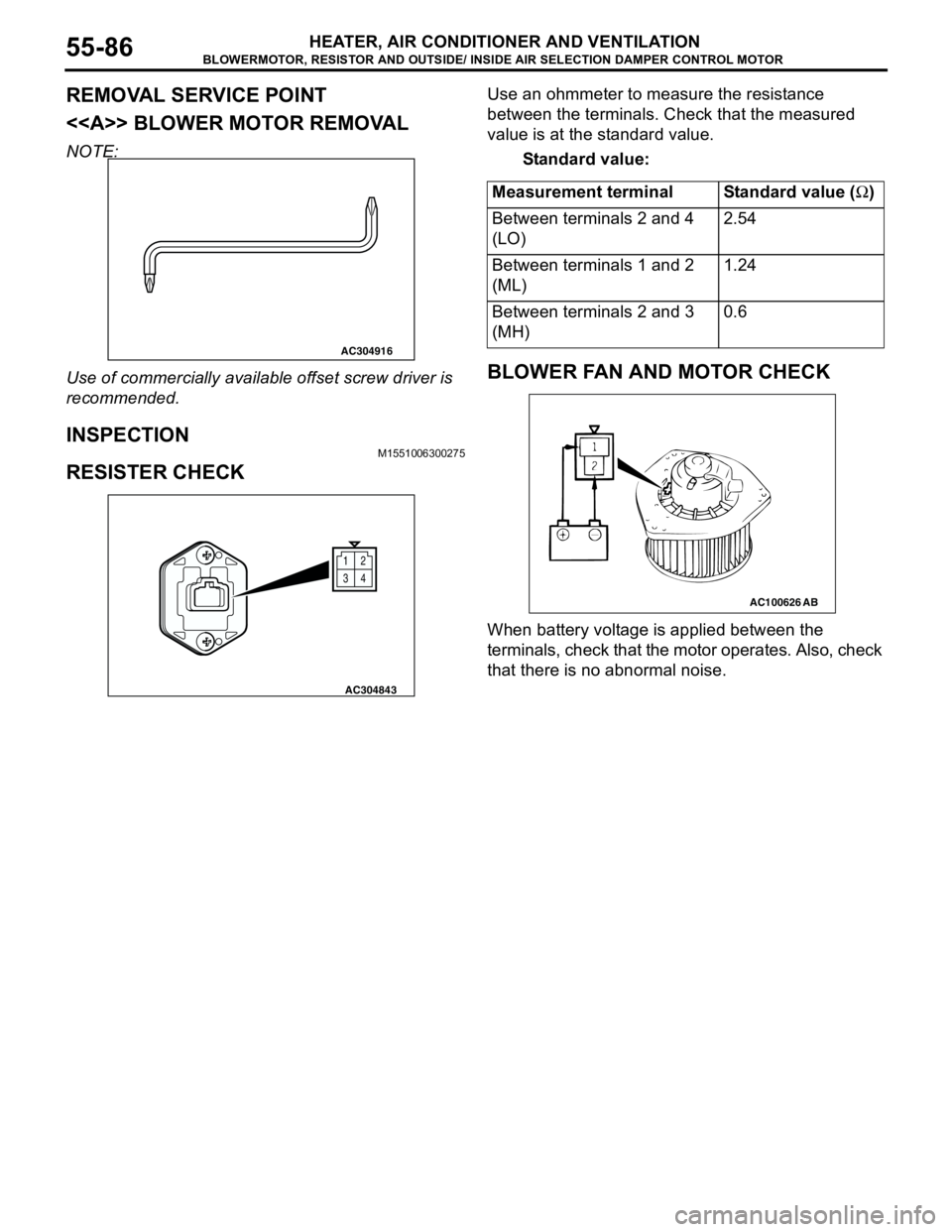
INSPECTIONM1551006300275
RESISTER CHECK
Use an ohmmeter to measure the resistance
between the terminals. Check that the measured
value is at the standard value.
Standard value:
BLOWER FAN AND MOTOR CHECK
When battery voltage is applied between the
terminals, check that the motor operates. Also, check
that there is no abnormal noise.
AC304916
12
34
AC304843
Measurement terminal Standard value (Ω)
Between terminals 2 and 4
(LO)2.54
Between terminals 1 and 2
(ML)1.24
Between terminals 2 and 3
(MH)0.6
AC100626AB
Page 571 of 788
BLOWERMOTOR, RESISTOR AND OUTSIDE/ INSIDE AIR SELECTION DAMPER CONTROL MOTOR
HEATER, AIR CONDITIONER AND VENTILATION55-87
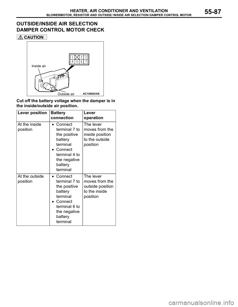
OUTSIDE/INSIDE AIR SELECTION
DAMPER CONTROL MOTOR CHECK
CAUTION
Cut off the battery voltage when the damper is in
the inside/outside air position.
Lever position Battery
connectionLever
operation
At the inside
position•Connect
terminal 7 to
the positive
battery
terminal
•Connect
terminal 4 to
the negative
battery
terminalThe lever
moves from the
inside position
to the outside
position
At the outside
position•Connect
terminal 7 to
the positive
battery
terminal
•Connect
terminal 6 to
the negative
battery
terminalThe lever
moves from the
outside position
to the inside
position
AC100625
Inside air
Outside air
AE
Page 574 of 788
Page 579 of 788
COMPRESSOR ASSEMBLY AND TENSION PULLEY
HEATER, AIR CONDITIONER AND VENTILATION55-95
>>B<< SNAP RING INSTALLATION
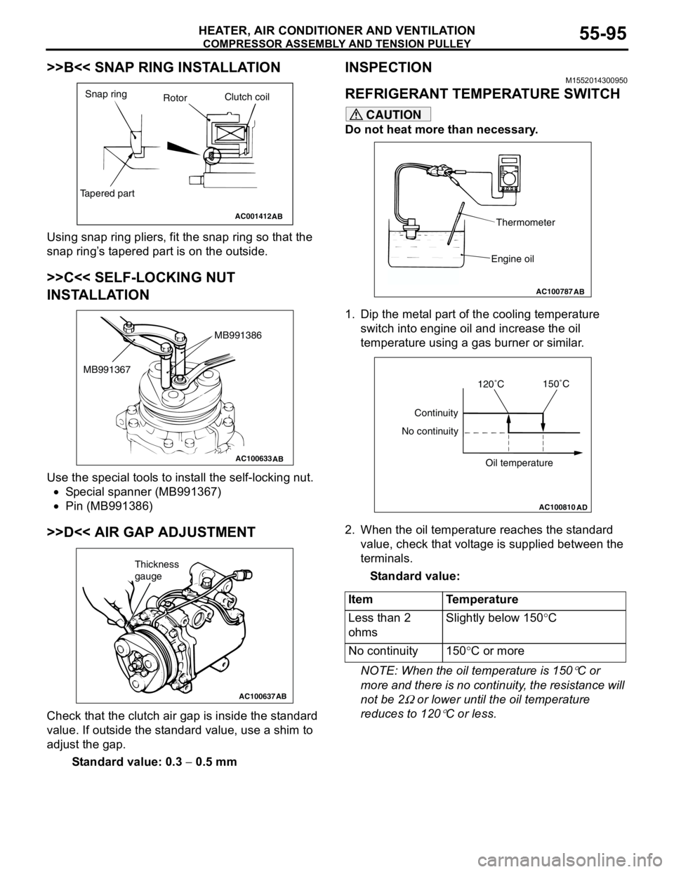
Using snap ring pliers, fit the snap ring so that the
snap ring’s tapered part is on the outside.
>>C<< SELF-LOCKING NUT
INSTALLATION
Use the special tools to install the self-locking nut.
•Special spanner (MB991367)
•Pin (MB991386)
>>D<< AIR GAP ADJUSTMENT
Check that the clutch air gap is inside the standard
value. If outside the standard value, use a shim to
adjust the gap.
Standard value: 0.3 − 0.5 mm
INSPECTIONM1552014300950
REFRIGERANT TEMPERATURE SWITCH
CAUTION
Do not heat more than necessary.
1. Dip the metal part of the cooling temperature
switch into engine oil and increase the oil
temperature using a gas burner or similar.
2. When the oil temperature reaches the standard
value, check that voltage is supplied between the
terminals.
Standard value:
NOTE: When the oil temperature is 150
°C or
more and there is no continuity, the resistance will
not be 2
Ω or lower until the oil temperature
reduces to 120
°C or less.
AC001412
Snap ring
RotorClutch coil
Tapered part
AB
AC100633AB
MB991386
MB991367
AC100637AB
Thickness
gauge
Item Temperature
Less than 2
ohmsSlightly below 150°C
No continuity 150°C or more
AC100787
Thermometer
Engine oil
AB
AC100810
Continuity
No continuity
Oil temperature
AD
120˚C150˚C
Page 582 of 788
REFRIGERANT LINE
HEATER, AIR CONDITIONER AND VENTILATION55-98
REFRIGERANT LINE
REMOVAL AND INSTALLATION
Pre-removal and Post-installation Operation
•Refrigerant Draining and Refilling (Refer to P.55-70.)
•Air Cleaner Removal and Installation (Refer to GROUP
15, Air cleaner P.15-3.)
•Radiator Grille Removal and Installation (Refer to
GROUP 51, Front bumper P.51-2.)
AC304553
1
2
3
45
6
7
8N
N
N
N
N
8 8
8
8
High-pressure
side service valve
Low-pressure side
service valve
4.9 ± 0.9 N·m 13 ± 1 N·m
4.9 ± 0.9 N·m
12 ± 2 N·m
AB
6
A/C compressor oil: SUN PAG 56 -Pipe coupling
O-ringO-ring
1, 2, 3,
5, 6
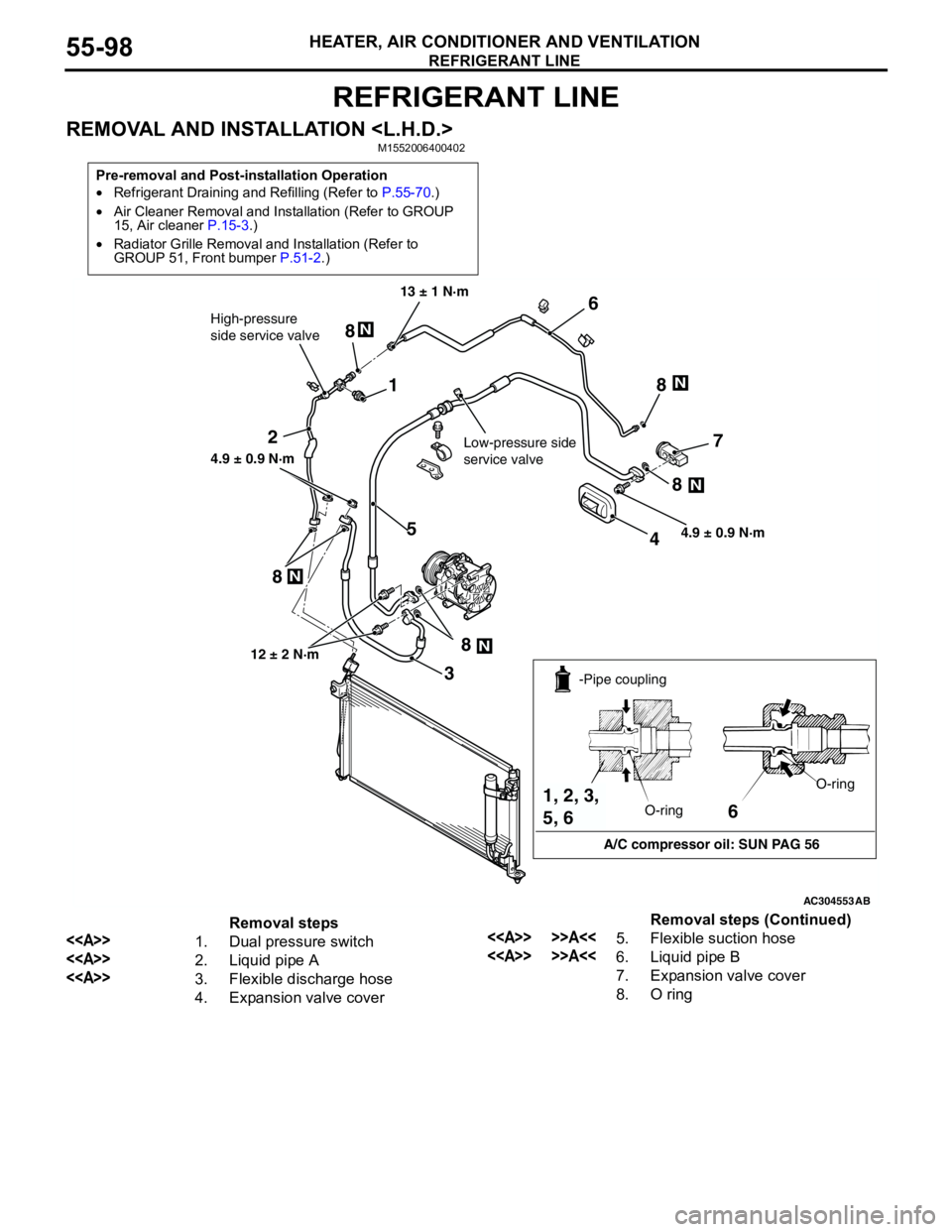
Removal steps
<>1. Dual pressure switch
<>2. Liquid pipe A
<>3. Flexible discharge hose
4. Expansion valve cover
<> >>A<<5. Flexible suction hose
<> >>A<<6. Liquid pipe B
7. Expansion valve cover
8. O ringRemoval steps (Continued)
Page 583 of 788
REFRIGERANT LINE
HEATER, AIR CONDITIONER AND VENTILATION55-99
REMOVAL SERVICE POINT
<> HOSE/PIPE DISCONNECTION
CAUTION
As the compressor oil and receiver are highly
moisture absorbent, use a non-porous material
to plug the hose and nipples.
To prevent the entry of other foreign bodies, plug the
condenser, compressor, and expansion valve
nipples.
INSTALLATION SERVICE POINT
>>A<< SUCTION HOSE INSTALLATION
When replacing the suction hose, refill them with a
specified amount of compressor oil, and then install
them.
Compressor oil: SUN PAG 56
Quantity: Suction hose: 10 cm
3
REMOVAL AND INSTALLATION
Pre-removal and Post-installation Operation
•Refrigerant Draining and Refilling (Refer to P.55-70.)
•Air Cleaner Removal and Installation (Refer to GROUP
15, Air cleaner P.15-3.)
•Radiator Grille Removal and Installation (Refer to
GROUP 51, Front bumper P.51-2.)
AC304554
1
2
3
4
5
6
7
8N
8N
8N
N8 8
N
4.9±0.9 N·m
Low-pressure side
service valve 13 ± 1 N·mHigh-pressure
Side Service Valve
12 ± 2 N·m
4.9 ± 0.9 N·m
AB
6
A/C compressor oil: SUN PAG 56 -Pipe coupling
O-ringO-ring
1, 2, 3,
5, 6
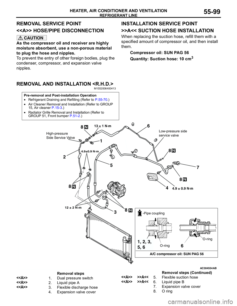
Removal steps
<>1. Dual pressure switch
<>2. Liquid pipe A
<>3. Flexible discharge hose
4. Expansion valve cover
<> >>A<<5. Flexible suction hose
<> >>A<<6. Liquid pipe B
7. Expansion valve cover
8. O ringRemoval steps (Continued)
Page 585 of 788
DUCTS
HEATER, AIR CONDITIONER AND VENTILATION55-101
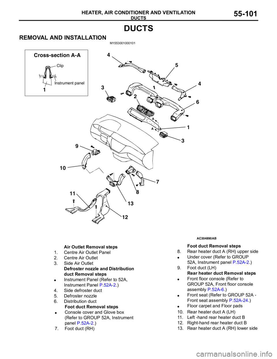
DUCTS
REMOVAL AND INSTALLATIONM1553001000101
AC304890
7
8
13
12 11 109364 5 4
3
2
1
AB A
A
Clip
Instrument panel
1 Cross-section A-A
Air Outlet Removal steps
1. Centre Air Outlet Panel
2. Centre Air Outlet
3. Side Air Outlet
Defroster nozzle and Distribution
duct Removal steps
•Instrument Panel (Refer to 52A,
Instrument Panel P.52A-2.)
4. Side defroster duct
5. Defroster nozzle
6. Distribution duct
Foot duct Removal steps
•Console cover and Glove box
(Refer to GROUP 52A, Instrument
panel P.52A-2.)
7. Foot duct (RH)8. Rear heater duct A (RH) upper side
•Under cover (Refer to GROUP
52A, Instrument panel P.52A-2.)
9. Foot duct (LH)
Rear heater duct Removal steps
•Front floor console (Refer to
GROUP 52A, Front floor console
assembly P.52A-6.)
•Front seat (Refer to GROUP 52A -
Front seat assembly P.52A-24.)
•Floor carpet and Floor pads
10. Rear heater duct A (LH)
11. Left -hand rear heater duct B
12. Right-hand rear heater duct B
13. Rear heater duct A (RH) lower sideFoot duct Removal steps
Page 592 of 788
SENSOR
COMPONENT LOCATIONS70-6
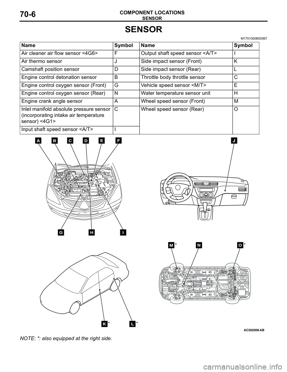
SENSOR
M1701000600567
NOTE: *: also equipped at the right side.Name Symbol Name Symbol
Air cleaner air flow sensor <4G6> F Output shaft speed sensor I
Air thermo sensor J Side impact sensor (Front) K
Camshaft position sensor D Side impact sensor (Rear) L
Engine control detonation sensor B Throttle body throttle sensor C
Engine control oxygen sensor (Front) G Vehicle speed sensor
Engine control oxygen sensor (Rear) N Water temperature sensor unit H
Engine crank angle sensor A Wheel speed sensor (Front) M
Inlet manifold absolute pressure sensor
(incorporating intake air temperature
sensor) <4G1>C Wheel speed sensor (Rear) O
Input shaft speed sensor I
AC302006AB
BDCFEA
GHI
J
KL
MNO
*
***