Side MITSUBISHI LANCER 2005 Workshop Manual
[x] Cancel search | Manufacturer: MITSUBISHI, Model Year: 2005, Model line: LANCER, Model: MITSUBISHI LANCER 2005Pages: 788, PDF Size: 45.98 MB
Page 2 of 788

WARNINGS REGARDING SERVICING OF SUPPLEMENTAL
RESTRAINT SYSTEM (SRS) EQUIPPED VEHICLES
(1) Improper service or maintenance of any component of the SRS or any SRS-related component,
can lead to personal injury or death to service personnel (from inadvertent firing of the air bag)
or to the driver and passenger (from rendering the SRS inoperative).
(2) The SRS components and seat belt with pretensioner should not be subjected to heat, so
remove the SRS-ECU, driver’s and front passenger’s air bag modules, clock spring, side air bag
modules, and seat belt -pre-tensioner before drying or baking the vehicle after painting.
• SRS-ECU, air bag module and clock spring 93°C or more
• Seat belt with pre-tensioner: 90°C or more
(3) Service or maintenance of any SRS component or SRS-related component must be performed
only at an authorized MITSUBISHI dealer.
(4) MITSUBISHI dealer personnel must thoroughly review this Manual, and especially its GROUP
52B - Supplemental Restraint System (SRS), before beginning any service or maintenance of
any component of the SRS or any SRS-related component.
NOTE
Section titles with asterisks (*) in the table of contents in each group indicate operations requiring warnings.
Page 10 of 788

ON-VEHICLE SERVICE
ENGINE LUBRICATION12-4
ON-VEHICLE SERVICE
ENGINE OIL CHECKM1121000900342
1. Pull out the engine oil level gauge slowly and
check that the oil level is in the illustrated range.
2. Check that the oil is not excessively dirty, that
there is no coolant or petrol mixed in, and that it
has sufficient viscosity.
ENGINE OIL REPLACEMENTM1121001000416
1. Start the engine and allow it to warm up until the
temperature of the coolant reaches 80 °C to 90
°C.
2. Remove the engine oil filler cap.
CAUTION
Use care as engine oil could be hot.
3. Remove the engine oil pan drain plug to drain
engine oil.4. Install a new engine oil pan drain plug gasket so
that it faces in the direction shown in the
illustration, and then tighten the engine oil pan
drain plug to the specified torque.
Tightening torque: 39 ± 5 N⋅m
NOTE: Install the engine oil pan drain plug gasket
so it faces in the direction shown in the illustration.
5. Refill with specified quantity of engine oil.
Specified Engine Oil (ACEA and API
classification): ACEA A1, A2 or A3/API SG or
higher
Total quantity (Includes volume inside engine
oil filter):
3.3 L <4G1>
4.3 L <4G6>
6. Install the engine oil filler cap.
7. Check engine oil level.
ENGINE OIL FILTER REPLACEMENTM1121001100383
1. Start the engine and allow it to warm up until the
temperature of the coolant reaches 80 °C to 90
°C.
2. Remove the engine oil filler cap.
CAUTION
Use care as engine oil could be hot.
3. Remove the engine oil pan drain plug to drain
engine oil.
4. Remove the under cover.
ACX00892 AC
Good
MaximumMinimum
<4G1>
AC205268
Maximum MinimumGood
AC
<4G6>
AC208299
Engine oil pan
AC
Engine oip pan
drain plug
Engine oip pan
drain plug
Engine oil
pan side
AC301513
Page 11 of 788
ON-VEHICLE SERVICE
ENGINE LUBRICATION12-5
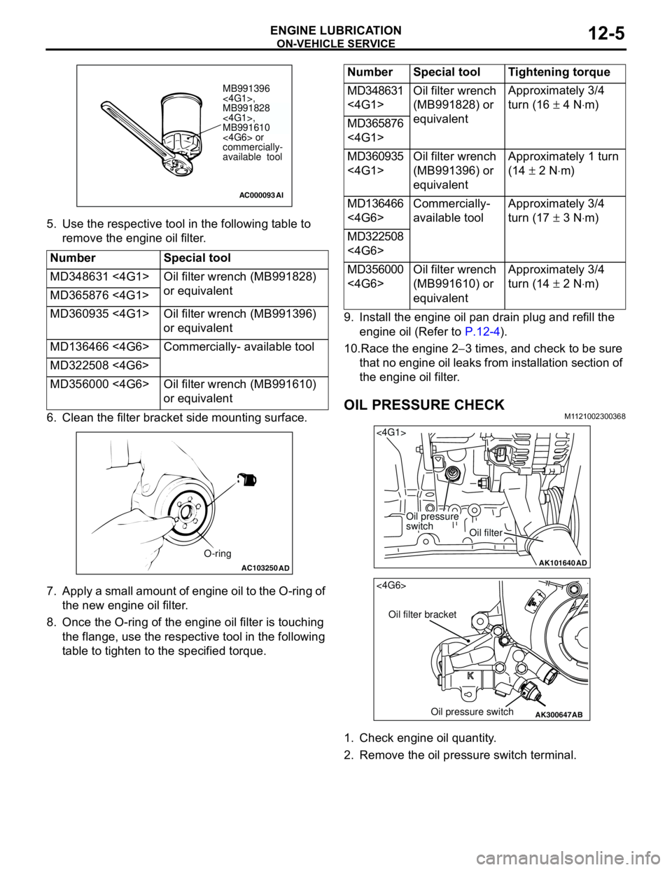
5. Use the respective tool in the following table to
remove the engine oil filter.
6. Clean the filter bracket side mounting surface.
7. Apply a small amount of engine oil to the O-ring of
the new engine oil filter.
8. Once the O-ring of the engine oil filter is touching
the flange, use the respective tool in the following
table to tighten to the specified torque.9. Install the engine oil pan drain plug and refill the
engine oil (Refer to P.12-4).
10.Race the engine 2−3 times, and check to be sure
that no engine oil leaks from installation section of
the engine oil filter.
OIL PRESSURE CHECKM1121002300368
1. Check engine oil quantity.
2. Remove the oil pressure switch terminal. Number Special tool
MD348631 <4G1> Oil filter wrench (MB991828)
or equivalent
MD365876 <4G1>
MD360935 <4G1> Oil filter wrench (MB991396)
or equivalent
MD136466 <4G6> Commercially- available tool
MD322508 <4G6>
MD356000 <4G6> Oil filter wrench (MB991610)
or equivalent
AC000093
MB991396
<4G1>,
MB991828
<4G1>,
MB991610
<4G6> or
commercially-
available tool
AI
AC103250AD
O-ring
Number Special tool Tightening torque
MD348631
<4G1>Oil filter wrench
(MB991828) or
equivalentApproximately 3/4
turn (16 ± 4 N⋅m)
MD365876
<4G1>
MD360935
<4G1>Oil filter wrench
(MB991396) or
equivalentApproximately 1 turn
(14 ± 2 N⋅m)
MD136466
<4G6>Commercially-
available toolApproximately 3/4
turn (17 ± 3 N⋅m)
MD322508
<4G6>
MD356000
<4G6>Oil filter wrench
(MB991610) or
equivalentApproximately 3/4
turn (14 ± 2 N⋅m)
AK101640
<4G1>
Oil pressure
switch
Oil filter
AD
AK300647
AB
<4G6>
Oil filter bracket
Oil pressure switch
Page 21 of 788
TROUBLESHOOTING
ENGINE COOLING14-7
CIRCUIT OPERATION
•The cooling fan motor drive control unit is
powered from fusible link (2).
•The engine-ECU
uses input signals from the A/C switch, the
water temperature sensor unit and the vehicle
speed sensor
sensor to control the speed of the cooling
fan motor (L.H.) and the cooling fan motor (R.H.)
<4G1 (Vehicles with A/C)> or A/C condenser fan
motor <4G6>.
•The engine-ECU
controls the cooling fan motor drive control
unit to activate the cooling fan motor (L.H.) and
the cooling fan motor (R.H.) <4G1 (Vehicles with
A/C)> or A/C condenser fan motor <4G6>.
TECHNICAL DESCRIPTION
•The cause could be a malfunction of the cooling
fan motor drive control unit power supply or earth
circuit.
•If the communication line wiring harness between
the cooling fan motor drive control unit and the
engine-ECU
short-circuited to earth, the cooling fan motor
(L.H.) and the cooling fan motor (R.H.) <4G1
(Vehicles with A/C)> or the A/C condenser fan
motor <4G6> will not rotate.
•The cause could also be a malfunction of the
cooling fan motor (L.H.).
•The cause could also be a malfunction of imput
signal from the A/C switch, the water temperature
sensor unit and the vehicle speed sensor
or the output shaft speed sensor to the
engine-ECU
•The cause could also be a malfunction of the
cooling fan motor drive control unit or the
engine-ECU
TROUBLESHOOTING HINTS
•Malfunction of fusible link (2)
•Malfunction of fan control relay
•Malfunction of cooling fan motor (L.H.)
•Malfunction of cooling fan motor drive control unit
•Malfunction of engine-ECU
engine-A/T-ECU
•Damaged wiring harness or connector
DIAGNOSIS
STEP 1. Check the cooling fan motor (L.H.).
Refer to P.14-25.
Q: Is the cooling fan motor (L.H.) in good condition?
YES :
Go to Step 2 .
NO : Replace the cooling fan motor (L.H.) (Refer
to P.14-35). Then go to Step 24 .
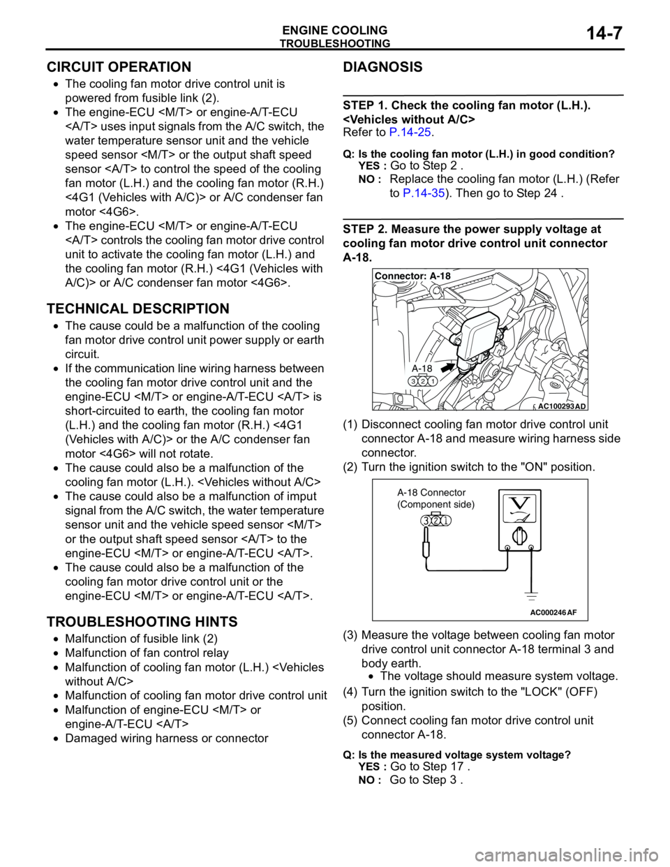
STEP 2. Measure the power supply voltage at
cooling fan motor drive control unit connector
A-18.
(1) Disconnect cooling fan motor drive control unit
connector A-18 and measure wiring harness side
connector.
(2) Turn the ignition switch to the "ON" position.
(3) Measure the voltage between cooling fan motor
drive control unit connector A-18 terminal 3 and
body earth.
•The voltage should measure system voltage.
(4) Turn the ignition switch to the "LOCK" (OFF)
position.
(5) Connect cooling fan motor drive control unit
connector A-18.
Q: Is the measured voltage system voltage?
YES :
Go to Step 17 .
NO : Go to Step 3 .
AC100293
A-18
321
Connector: A-18
AD
AC000246AF
A-18 Connector
(Component side)
Page 22 of 788
TROUBLESHOOTING
ENGINE COOLING14-8
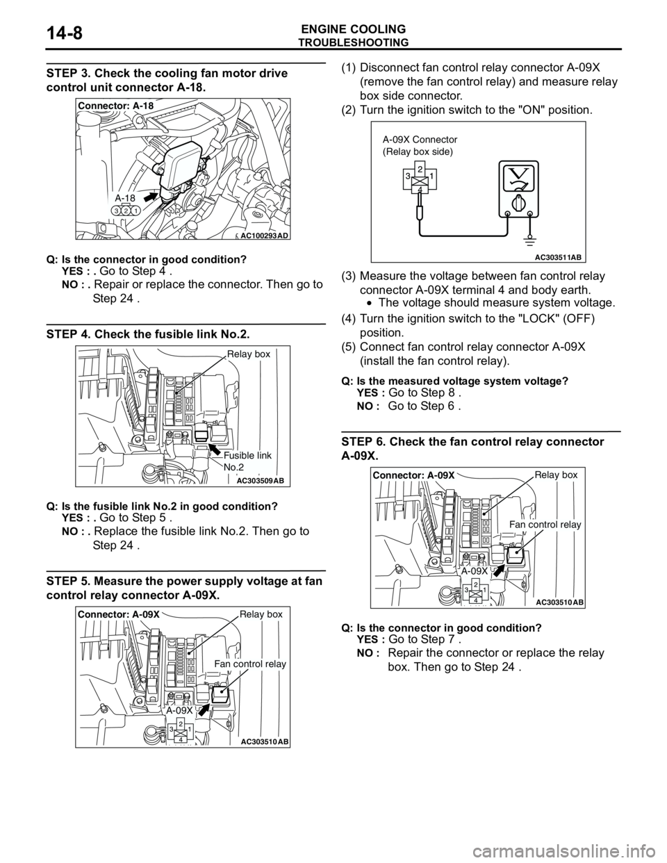
STEP 3. Check the cooling fan motor drive
control unit connector A-18.
Q: Is the connector in good condition?
YES : .
Go to Step 4 .
NO : . Repair or replace the connector. Then go to
Step 24 .
STEP 4. Check the fusible link No.2.
Q: Is the fusible link No.2 in good condition?
YES : .
Go to Step 5 .
NO : . Replace the fusible link No.2. Then go to
Step 24 .
STEP 5. Measure the power supply voltage at fan
control relay connector A-09X.(1) Disconnect fan control relay connector A-09X
(remove the fan control relay) and measure relay
box side connector.
(2) Turn the ignition switch to the "ON" position.
(3) Measure the voltage between fan control relay
connector A-09X terminal 4 and body earth.
•The voltage should measure system voltage.
(4) Turn the ignition switch to the "LOCK" (OFF)
position.
(5) Connect fan control relay connector A-09X
(install the fan control relay).
Q: Is the measured voltage system voltage?
YES :
Go to Step 8 .
NO : Go to Step 6 .
STEP 6. Check the fan control relay connector
A-09X.
Q: Is the connector in good condition?
YES :
Go to Step 7 .
NO : Repair the connector or replace the relay
box. Then go to Step 24 .
AC100293
A-18
321
Connector: A-18
AD
AC303509AB
Fusible link
No.2
Relay box
AC303510AB
Fan control relay
Relay boxConnector: A-09X
A-09X
AC303511AB
A-09X Connector
(Relay box side)
AC303510AB
Fan control relay
Relay boxConnector: A-09X
A-09X
Page 23 of 788
TROUBLESHOOTING
ENGINE COOLING14-9
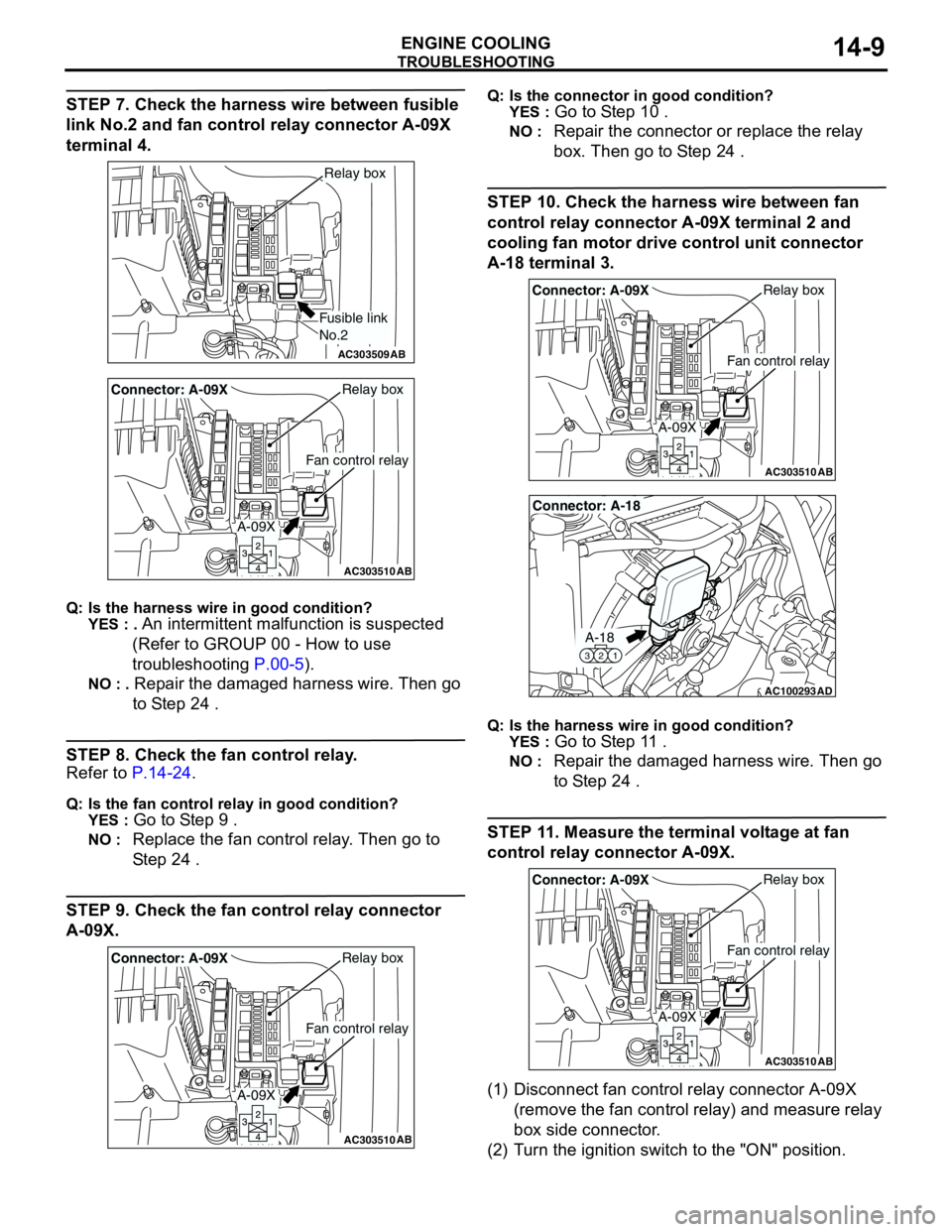
STEP 7. Check the harness wire between fusible
link No.2 and fan control relay connector A-09X
terminal 4.
Q: Is the harness wire in good condition?
YES : .
An intermittent malfunction is suspected
(Refer to GROUP 00 - How to use
troubleshooting P.00-5).
NO : . Repair the damaged harness wire. Then go
to Step 24 .
STEP 8. Check the fan control relay.
Refer to P.14-24.
Q: Is the fan control relay in good condition?
YES :
Go to Step 9 .
NO : Replace the fan control relay. Then go to
Step 24 .
STEP 9. Check the fan control relay connector
A-09X.
Q: Is the connector in good condition?
YES :
Go to Step 10 .
NO : Repair the connector or replace the relay
box. Then go to Step 24 .
STEP 10. Check the harness wire between fan
control relay connector A-09X terminal 2 and
cooling fan motor drive control unit connector
A-18 terminal 3.
Q: Is the harness wire in good condition?
YES :
Go to Step 11 .
NO : Repair the damaged harness wire. Then go
to Step 24 .
STEP 11. Measure the terminal voltage at fan
control relay connector A-09X.
(1) Disconnect fan control relay connector A-09X
(remove the fan control relay) and measure relay
box side connector.
(2) Turn the ignition switch to the "ON" position.
AC303509AB
Fusible link
No.2
Relay box
AC303510AB
Fan control relay
Relay boxConnector: A-09X
A-09X
AC303510AB
Fan control relay
Relay boxConnector: A-09X
A-09X
AC303510AB
Fan control relay
Relay boxConnector: A-09X
A-09X
AC100293
A-18
321
Connector: A-18
AD
AC303510AB
Fan control relay
Relay boxConnector: A-09X
A-09X
Page 24 of 788
TROUBLESHOOTING
ENGINE COOLING14-10
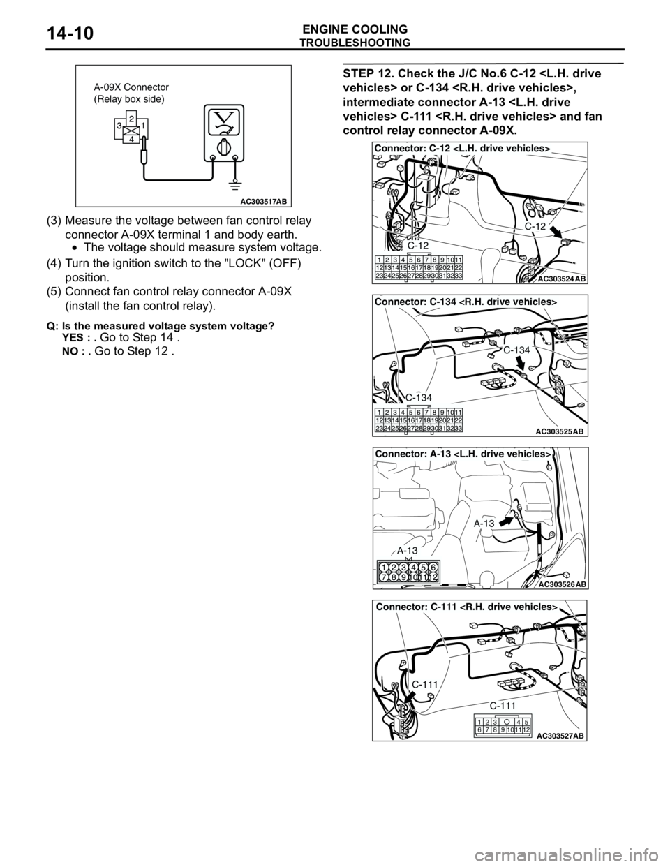
(3) Measure the voltage between fan control relay
connector A-09X terminal 1 and body earth.
•The voltage should measure system voltage.
(4) Turn the ignition switch to the "LOCK" (OFF)
position.
(5) Connect fan control relay connector A-09X
(install the fan control relay).
Q: Is the measured voltage system voltage?
YES : .
Go to Step 14 .
NO : . Go to Step 12 .
STEP 12. Check the J/C No.6 C-12
intermediate connector A-13
control relay connector A-09X.
AC303517AB
A-09X Connector
(Relay box side)
AC303524
Connector: C-12
AB
C-12
C-12
AC303525
Connector: C-134
AB
C-134
C-134
AC303526
Connector: A-13
AB
A-13
A-13
AC303527
Connector: C-111
AB
C-111
C-111
615
121179
810234
Page 25 of 788
TROUBLESHOOTING
ENGINE COOLING14-11
Q: Are there connectors in good condition?
YES : .
Go to Step 13 .
NO : . Repair or replace the connector. Then go to
Step 24 .
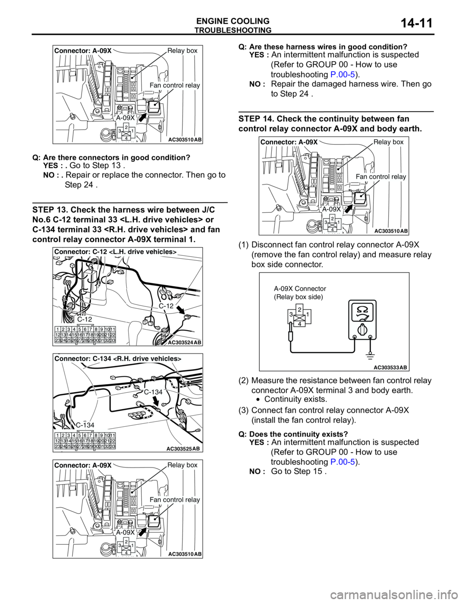
STEP 13. Check the harness wire between J/C
No.6 C-12 terminal 33
C-134 terminal 33
control relay connector A-09X terminal 1.
Q: Are these harness wires in good condition?
YES :
An intermittent malfunction is suspected
(Refer to GROUP 00 - How to use
troubleshooting P.00-5).
NO : Repair the damaged harness wire. Then go
to Step 24 .
STEP 14. Check the continuity between fan
control relay connector A-09X and body earth.
(1) Disconnect fan control relay connector A-09X
(remove the fan control relay) and measure relay
box side connector.
(2) Measure the resistance between fan control relay
connector A-09X terminal 3 and body earth.
•Continuity exists.
(3) Connect fan control relay connector A-09X
(install the fan control relay).
Q: Does the continuity exists?
YES :
An intermittent malfunction is suspected
(Refer to GROUP 00 - How to use
troubleshooting P.00-5).
NO : Go to Step 15 .
AC303510AB
Fan control relay
Relay boxConnector: A-09X
A-09X
AC303524
Connector: C-12
AB
C-12
C-12
AC303525
Connector: C-134
AB
C-134
C-134
AC303510AB
Fan control relay
Relay boxConnector: A-09X
A-09X
AC303510AB
Fan control relay
Relay boxConnector: A-09X
A-09X
AC303533AB
A-09X Connector
(Relay box side)
Page 26 of 788
TROUBLESHOOTING
ENGINE COOLING14-12
STEP 15. Check the fan control relay connector
A-09X.
Q: Is the connector in good condition?
YES :
Go to Step 16 .
NO : Repair the connector or replace the relay
box. Then go to Step 24 .
STEP 16. Check the harness wire between fan
control relay connector A-09X terminal 3 and
body earth.
Q: Is the harness wire in good condition?
YES :
An intermittent malfunction is suspected
(Refer to GROUP 00 - How to use
troubleshooting P.00-5).
NO : Repair the damaged harness wire. Then go
to Step 24 .
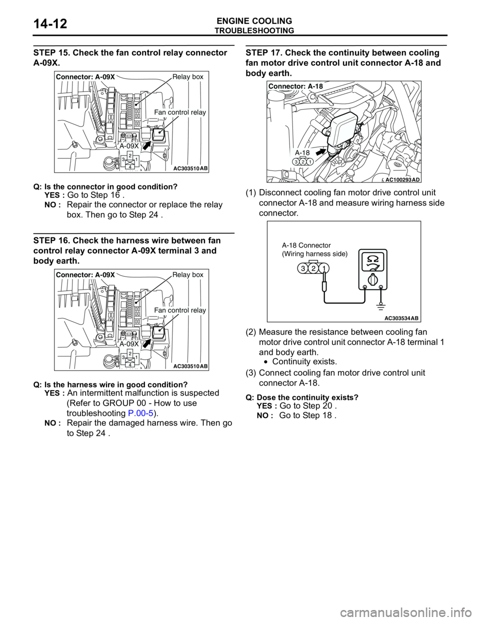
STEP 17. Check the continuity between cooling
fan motor drive control unit connector A-18 and
body earth.
(1) Disconnect cooling fan motor drive control unit
connector A-18 and measure wiring harness side
connector.
(2) Measure the resistance between cooling fan
motor drive control unit connector A-18 terminal 1
and body earth.
•Continuity exists.
(3) Connect cooling fan motor drive control unit
connector A-18.
Q: Dose the continuity exists?
YES :
Go to Step 20 .
NO : Go to Step 18 .
AC303510AB
Fan control relay
Relay boxConnector: A-09X
A-09X
AC303510AB
Fan control relay
Relay boxConnector: A-09X
A-09X
AC100293
A-18
321
Connector: A-18
AD
AC303534AB
A-18 Connector
(Wiring harness side)
Page 29 of 788
TROUBLESHOOTING
ENGINE COOLING14-15
STEP 22. Check the cooling fan motor drive
control unit.
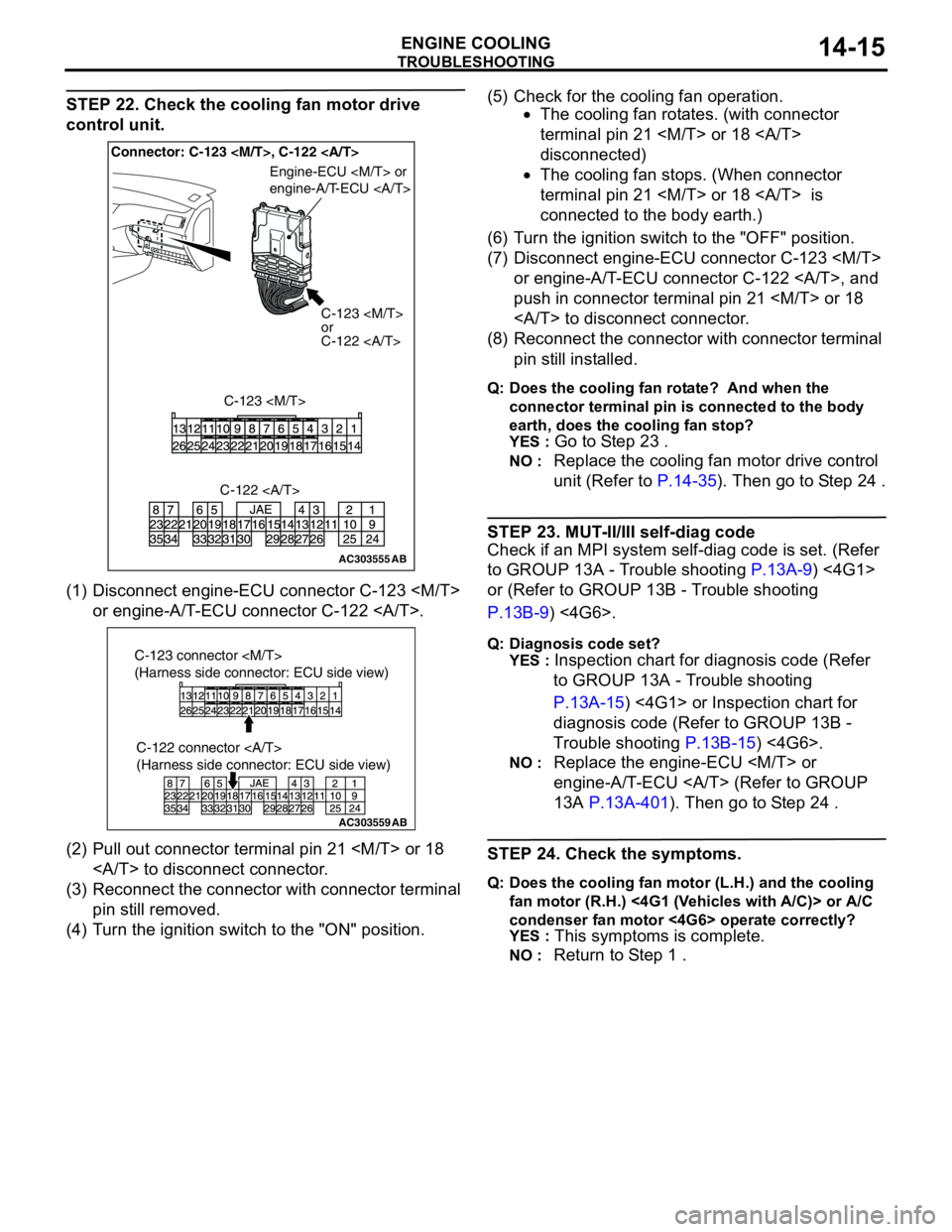
(1) Disconnect engine-ECU connector C-123
or engine-A/T-ECU connector C-122 .
(2) Pull out connector terminal pin 21
to disconnect connector.
(3) Reconnect the connector with connector terminal
pin still removed.
(4) Turn the ignition switch to the "ON" position.(5) Check for the cooling fan operation.
•The cooling fan rotates. (with connector
terminal pin 21
disconnected)
•The cooling fan stops. (When connector
terminal pin 21
connected to the body earth.)
(6) Turn the ignition switch to the "OFF" position.
(7) Disconnect engine-ECU connector C-123
or engine-A/T-ECU connector C-122 , and
push in connector terminal pin 21
to disconnect connector.
(8) Reconnect the connector with connector terminal
pin still installed.
Q: Does the cooling fan rotate? And when the
connector terminal pin is connected to the body
earth, does the cooling fan stop?
YES :
Go to Step 23 .
NO : Replace the cooling fan motor drive control
unit (Refer to P.14-35). Then go to Step 24 .
STEP 23. MUT-II/III self-diag code
Check if an MPI system self-diag code is set. (Refer
to GROUP 13A - Trouble shooting P.13A-9) <4G1>
or (Refer to GROUP 13B - Trouble shooting
P.13B-9) <4G6>.
Q: Diagnosis code set?
YES :
Inspection chart for diagnosis code (Refer
to GROUP 13A - Trouble shooting
P.13A-15) <4G1> or Inspection chart for
diagnosis code (Refer to GROUP 13B -
Trouble shooting P.13B-15) <4G6>.
NO : Replace the engine-ECU
engine-A/T-ECU (Refer to GROUP
13A P.13A-401). Then go to Step 24 .
STEP 24. Check the symptoms.
Q: Does the cooling fan motor (L.H.) and the cooling
fan motor (R.H.) <4G1 (Vehicles with A/C)> or A/C
condenser fan motor <4G6> operate correctly?
YES :
This symptoms is complete.
NO : Return to Step 1 .
AC303555AB
Connector: C-123
C-123
or
C-122
C-123
Engine-ECU
engine-A/T-ECU
C-122
AC303559
C-122 connector
(Harness side connector: ECU side view)
AB
C-123 connector
(Harness side connector: ECU side view)