Side MITSUBISHI LANCER 2005 Workshop Manual
[x] Cancel search | Manufacturer: MITSUBISHI, Model Year: 2005, Model line: LANCER, Model: MITSUBISHI LANCER 2005Pages: 788, PDF Size: 45.98 MB
Page 549 of 788
TROUBLESHOOTING
HEATER, AIR CONDITIONER AND VENTILATION55-65
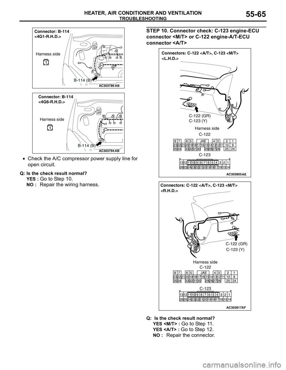
•Check the A/C compressor power supply line for
open circuit.
Q: Is the check result normal?
YES :
Go to Step 10.
NO : Repair the wiring harness.
STEP 10. Connector check: C-123 engine-ECU
connector
connector
Q: Is the check result normal?
YES
Go to Step 11.
YES : Go to Step 12.
NO : Repair the connector.
AC303786
Connector: B-114
<4G1-R.H.D.>
AB
Harness side
B-114 (B)
AC303794
Connector: B-114
<4G6-R.H.D.>
AB
Harness side
B-114 (B)
AC303805
Connectors: C-122 , C-123
C-122 (GR)
C-123 (Y)
C-122 Harness side
C-123
AE
AC303817
Connectors: C-122 , C-123
AF
C-122C-122 (GR)
C-123 (Y)
C-123 Harness side
Page 550 of 788
TROUBLESHOOTING
HEATER, AIR CONDITIONER AND VENTILATION55-66
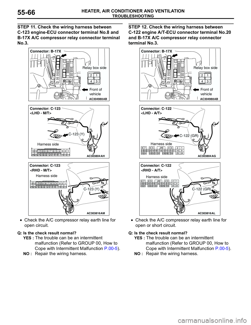
STEP 11. Check the wiring harness between
C-123 engine-ECU connector terminal No.8 and
B-17X A/C compressor relay connector terminal
No.3.
•Check the A/C compressor relay earth line for
open circuit.
Q: Is the check result normal?
YES :
The trouble can be an intermittent
malfunction (Refer to GROUP 00, How to
Cope with Intermittent Malfunction P.00-5).
NO : Repair the wiring harness.
STEP 12. Check the wiring harness between
C-122 engine A/T-ECU connector terminal No.20
and B-17X A/C compressor relay connector
terminal No.3.
•Check the A/C compressor relay earth line for
open or short circuit.
Q: Is the check result normal?
YES :
The trouble can be an intermittent
malfunction (Refer to GROUP 00, How to
Cope with Intermittent Malfunction P.00-5).
NO : Repair the wiring harness.
AC304988AB
Connector: B-17X
Front of
vehicle
1
3 2
4
Relay box side
AC303804
Connector: C-123
AH
Harness side
C-123 (Y)
AC303816
Connector: C-123
AM
Harness side
C-123 (Y)
AC304988AB
Connector: B-17X
Front of
vehicle
1
3 2
4
Relay box side
AC303804
Connector: C-122
AG
Harness side
C-122 (GR)
AC303816
Connector: C-122
AL
Harness side
C-122 (GR)
Page 551 of 788
TROUBLESHOOTING
HEATER, AIR CONDITIONER AND VENTILATION55-67
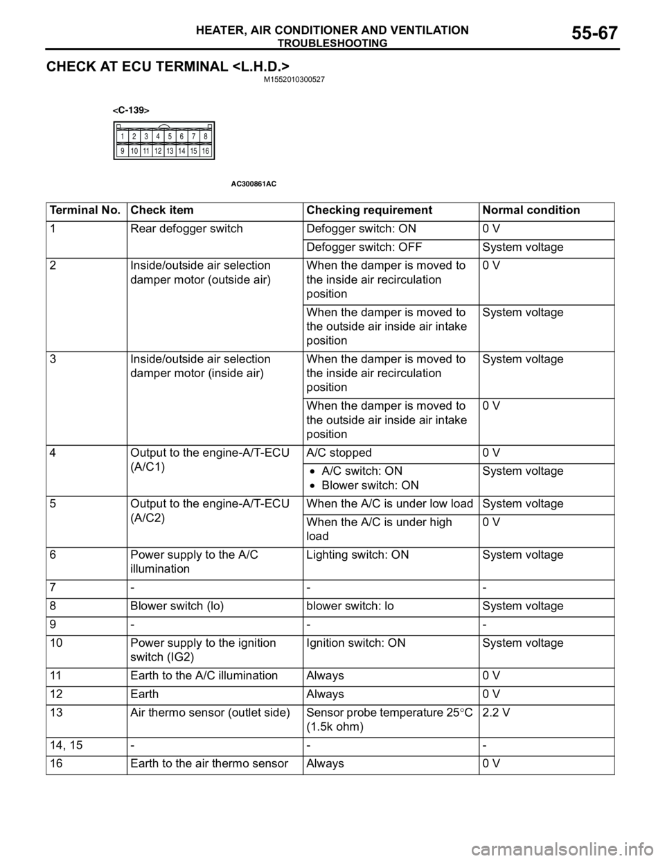
CHECK AT ECU TERMINAL
12
345
678
9 10111213141516
AC300861AC
Terminal No. Check item Checking requirement Normal condition
1 Rear defogger switch Defogger switch: ON 0 V
Defogger switch: OFF System voltage
2 Inside/outside air selection
damper motor (outside air)When the damper is moved to
the inside air recirculation
position0 V
When the damper is moved to
the outside air inside air intake
positionSystem voltage
3 Inside/outside air selection
damper motor (inside air)When the damper is moved to
the inside air recirculation
positionSystem voltage
When the damper is moved to
the outside air inside air intake
position0 V
4 Output to the engine-A/T-ECU
(A/C1)A/C stopped 0 V
•A/C switch: ON
•Blower switch: ONSystem voltage
5 Output to the engine-A/T-ECU
(A/C2)When the A/C is under low load System voltage
When the A/C is under high
load0 V
6 Power supply to the A/C
illuminationLighting switch: ON System voltage
7---
8 Blower switch (lo) blower switch: lo System voltage
9---
10 Power supply to the ignition
switch (IG2)Ignition switch: ON System voltage
11 Earth to the A/C illumination Always 0 V
12 Earth Always 0 V
13 Air thermo sensor (outlet side) Sensor probe temperature 25°C
(1.5k ohm)2.2 V
14, 15 - - -
16 Earth to the air thermo sensor Always 0 V
Page 552 of 788
TROUBLESHOOTING
HEATER, AIR CONDITIONER AND VENTILATION55-68
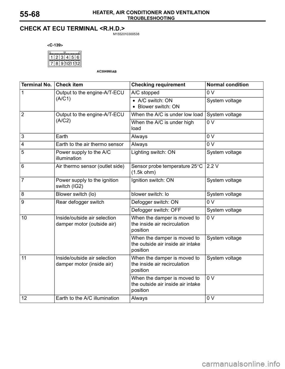
CHECK AT ECU TERMINAL
21
78
6 534
11
10912
AC304990
AB
Terminal No. Check item Checking requirement Normal condition
1 Output to the engine-A/T-ECU
(A/C1)A/C stopped 0 V
•A/C switch: ON
•Blower switch: ONSystem voltage
2 Output to the engine-A/T-ECU
(A/C2)When the A/C is under low load System voltage
When the A/C is under high
load0 V
3 Earth Always 0 V
4 Earth to the air thermo sensor Always 0 V
5 Power supply to the A/C
illuminationLighting switch: ON System voltage
6 Air thermo sensor (outlet side) Sensor probe temperature 25°C
(1.5k ohm)2.2 V
7 Power supply to the ignition
switch (IG2)Ignition switch: ON System voltage
8 Blower switch (lo) blower switch: lo System voltage
9 Rear defogger switch Defogger switch: ON 0 V
Defogger switch: OFF System voltage
10 Inside/outside air selection
damper motor (outside air)When the damper is moved to
the inside air recirculation
position0 V
When the damper is moved to
the outside air inside air intake
positionSystem voltage
11 Inside/outside air selection
damper motor (inside air)When the damper is moved to
the inside air recirculation
positionSystem voltage
When the damper is moved to
the outside air inside air intake
position0 V
12 Earth to the A/C illumination Always 0 V
Page 553 of 788
ON-VEHICLE SERVICE
HEATER, AIR CONDITIONER AND VENTILATION55-69
ON-VEHICLE SERVICE
SIGHT GLASS REFRIGERANT LEVEL
TEST
M1552008400378
1. Start the engine.
2. Operate the air-conditioner, and then set the
temperature to maximum cooling.
3. Hold the engine speed at 1500 r/min.
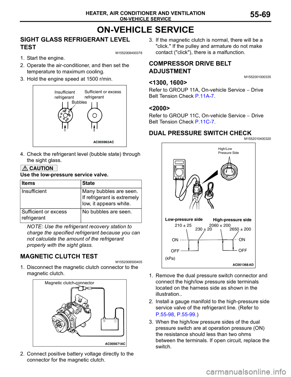
4. Check the refrigerant level (bubble state) through
the sight glass.
CAUTION
Use the low-pressure service valve.
NOTE: Use the refrigerant recovery station to
charge the specified refrigerant because you can
not calculate the amount of the refrigerant
properly with the sight glass.
MAGNETIC CLUTCH TESTM1552008500405
1. Disconnect the magnetic clutch connector to the
magnetic clutch.
2. Connect positive battery voltage directly to the
connector for the magnetic clutch.3. If the magnetic clutch is normal, there will be a
"click." If the pulley and armature do not make
contact ("click"), there is a malfunction.
COMPRESSOR DRIVE BELT
ADJUSTMENT
M1552001000335
<1300, 1600>
Refer to GROUP 11A, On-vehicle Service − Drive
Belt Tension Check P.11A-7.
<2000>
Refer to GROUP 11C, On-vehicle Service − Drive
Belt Tension Check P.11C-7.
DUAL PRESSURE SWITCH CHECKM1552010400320
1. Remove the dual pressure switch connector and
connect the high/low pressure side terminals
located on the harness side as shown in the
illustration..
2. Install a gauge manifold to the high-pressure side
service valve of the refrigerant line. (Refer to
P.55-98, P.55-99.)
3. When the high/low pressure sides of the dual
pressure switch are at operation pressure (ON)
the resistance should less than two ohms
between the terminals. If open circuit, replace the
switch. Items State
Insufficient Many bubbles are seen.
If refrigerant is extremely
low, it appears white.
Sufficient or excess
refrigerantNo bubbles are seen.
AC005963
Bubbles Insufficient
refrigerantSufficient or excess
refrigerant
AC
AC005671
Magnetic clutch connector
AC
AC001368AD High/Low
Pressure Side
Low-pressure side
High-pressure side
ON
OFFON
OFF
2650 ± 200 2060 ± 200230 ± 20 210 ± 25
(kPa)
Page 554 of 788
ON-VEHICLE SERVICE
HEATER, AIR CONDITIONER AND VENTILATION55-70
CHARGING M1552001200362
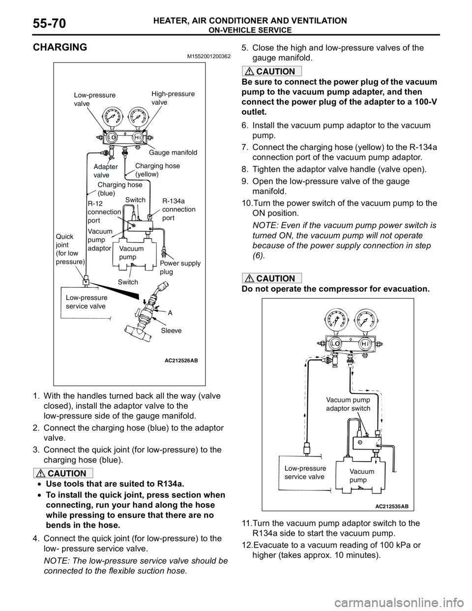
1. With the handles turned back all the way (valve
closed), install the adaptor valve to the
low-pressure side of the gauge manifold.
2. Connect the charging hose (blue) to the adaptor
valve.
3. Connect the quick joint (for low-pressure) to the
charging hose (blue).
CAUTION
•Use tools that are suited to R134a.
•To install the quick joint, press section when
connecting, run your hand along the hose
while pressing to ensure that there are no
bends in the hose.
4. Connect the quick joint (for low-pressure) to the
low- pressure service valve.
NOTE: The low-pressure service valve should be
connected to the flexible suction hose.5. Close the high and low-pressure valves of the
gauge manifold.
CAUTION
Be sure to connect the power plug of the vacuum
pump to the vacuum pump adapter, and then
connect the power plug of the adapter to a 100-V
outlet.
6. Install the vacuum pump adaptor to the vacuum
pump.
7. Connect the charging hose (yellow) to the R-134a
connection port of the vacuum pump adaptor.
8. Tighten the adaptor valve handle (valve open).
9. Open the low-pressure valve of the gauge
manifold.
10.Turn the power switch of the vacuum pump to the
ON position.
NOTE: Even if the vacuum pump power switch is
turned ON, the vacuum pump will not operate
because of the power supply connection in step
(6).
CAUTION
Do not operate the compressor for evacuation.
11.Turn the vacuum pump adaptor switch to the
R134a side to start the vacuum pump.
12.Evacuate to a vacuum reading of 100 kPa or
higher (takes approx. 10 minutes).
AC212526
AB
A
Sleeve Low-pressure
service valve Quick
joint
(for low
pressure)
SwitchVacuum
pump
Power supply
plug Vacuum
pump
adaptor R-12
connection
portCharging hose
(blue)
Adapter
valveCharging hose
(yellow)Gauge manifold
Switch
R-134a
connection
port Low-pressure
valveHigh-pressure
valve
AC212535
Vacuum
pump Low-pressure
service valve
AB
Vacuum pump
adaptor switch
Page 562 of 788
HEATER CONTROL ASSEMBLY AND A/C SWITCH
HEATER, AIR CONDITIONER AND VENTILATION55-78
INSTALLATION SERVICE POINT
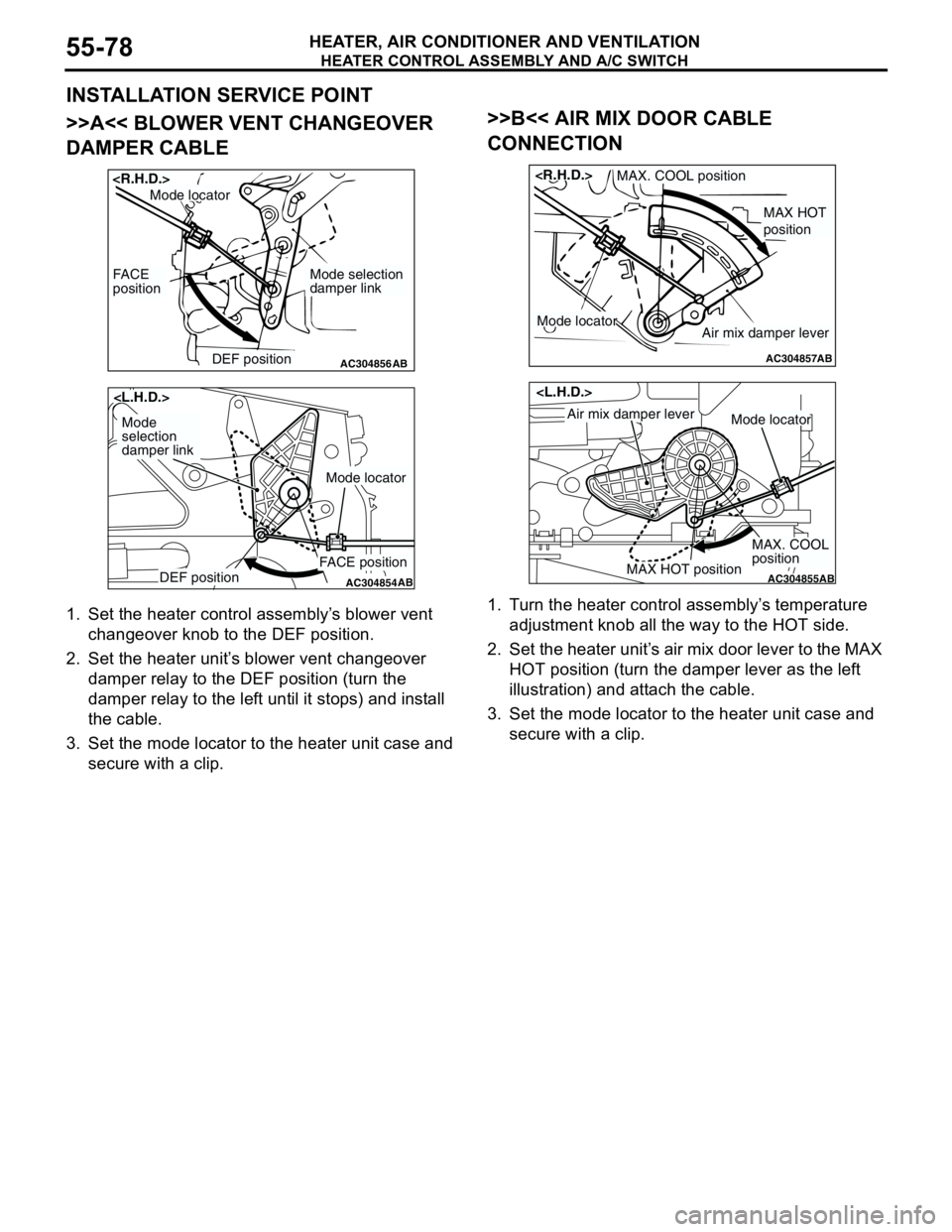
>>A<< BLOWER VENT CHANGEOVER
DAMPER CABLE
1. Set the heater control assembly’s blower vent
changeover knob to the DEF position.
2. Set the heater unit’s blower vent changeover
damper relay to the DEF position (turn the
damper relay to the left until it stops) and install
the cable.
3. Set the mode locator to the heater unit case and
secure with a clip.
>>B<< AIR MIX DOOR CABLE
CONNECTION
1. Turn the heater control assembly’s temperature
adjustment knob all the way to the HOT side.
2. Set the heater unit’s air mix door lever to the MAX
HOT position (turn the damper lever as the left
illustration) and attach the cable.
3. Set the mode locator to the heater unit case and
secure with a clip.
AC304856DEF position
FACE
position
AB
Mode selection
damper link
Mode locator
AC304854DEF positionFACE position
AB
Mode
selection
damper link
Mode locator
AC304857
MAX HOT
position
MAX. COOL position
AB
Air mix damper leverMode locator
AC304855MAX HOT position
MAX. COOL
position
AB
Air mix damper leverMode locator
Page 563 of 788
HEATER CONTROL ASSEMBLY AND A/C SWITCH
HEATER, AIR CONDITIONER AND VENTILATION55-79
INSPECTIONM1552014300927
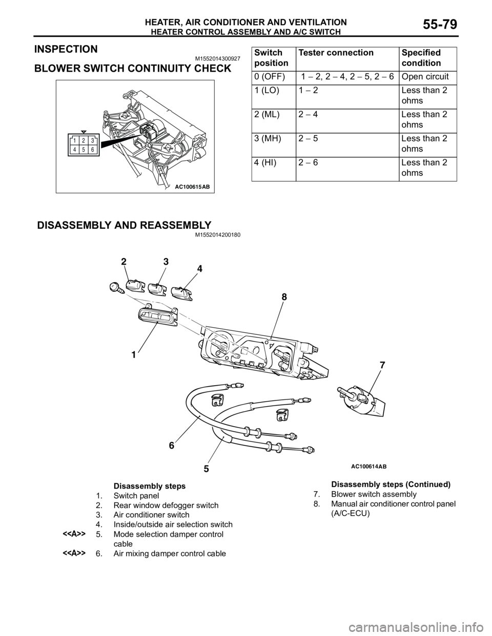
BLOWER SWITCH CONTINUITY CHECK
DISASSEMBLY AND REASSEMBLY
M1552014200180
12
6 3
45
AC100615AB
Switch
positionTester connection Specified
condition
0 (OFF) 1 − 2, 2 − 4, 2 − 5, 2 − 6 Open circuit
1 (LO) 1 − 2 Less than 2
ohms
2 (ML) 2 − 4 Less than 2
ohms
3 (MH) 2 − 5 Less than 2
ohms
4 (HI) 2 − 6 Less than 2
ohms
AC100614
1 23
4
5 67 8
AB
Disassembly steps
1. Switch panel
2. Rear window defogger switch
3. Air conditioner switch
4. Inside/outside air selection switch
<>5. Mode selection damper control
cable
<>6. Air mixing damper control cable7. Blower switch assembly
8. Manual air conditioner control panel
(A/C-ECU) Disassembly steps (Continued)
Page 564 of 788
HEATER CONTROL ASSEMBLY AND A/C SWITCH
HEATER, AIR CONDITIONER AND VENTILATION55-80
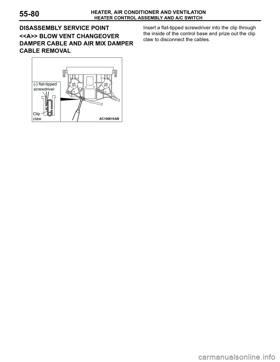
DISASSEMBLY SERVICE POINT
<> BLOW VENT CHANGEOVER
DAMPER CABLE AND AIR MIX DAMPER
CABLE REMOVALInsert a flat-tipped screwdriver into the clip through
the inside of the control base and prize out the clip
claw to disconnect the cables.
AC100619
AB
Clip
claw
(-) flat-tipped
screwdriver
Page 565 of 788
HEATER UNIT, HEATER CORE, BLOWER ASSEMBLY AND EVAPORATOR UNIT
HEATER, AIR CONDITIONER AND VENTILATION55-81
HEATER UNIT, HEATER CORE, BLOWER ASSEMBLY
AND EVAPORATOR UNIT
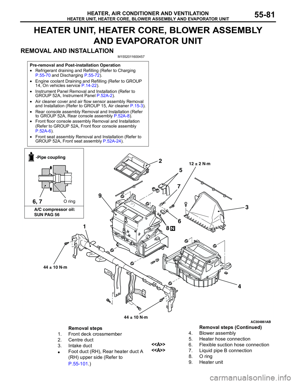
REMOVAL AND INSTALLATION
M1552011600457
Pre-removal and Post-installation Operation
•Refrigerant draining and Refilling (Refer to Charging
P.55-70 and Discharging P.55-72).
•Engine coolant Draining and Refilling (Refer to GROUP
14, On vehicles service P.14-22).
•Instrument Panel Removal and Installation (Refer to
GROUP 52A, Instrument Panel P.52A-2).
•Air cleaner cover and air flow sensor assembly Removal
and Installation (Refer to GROUP 15, Air cleaner P.15-3).
•Rear console assembly Removal and Installation (Refer
to GROUP 52A, Rear console assembly P.52A-8).
•Front floor console assembly Removal and Installation
(Refer to GROUP 52A, Front floor console assembly
P.52A-6).
•Front seat assembly Removal and Installation (Refer to
GROUP 52A, Front seat assembly P.52A-24).
AC304861
1
2
3
4 5
6
7
8
N
9
AB
12 ± 2 N·m
6, 7O ring -Pipe coupling
A/C compressor oil:
SUN PAG 56
44 ± 10 N·m
44 ± 10 N·m
Removal steps
1. Front deck crossmember
2. Centre duct
3. Intake duct
•Foot duct (RH), Rear heater duct A
(RH) upper side (Refer to
P.55-101.)4. Blower assembly
5. Heater hose connection
<>6. Flexible suction hose connection
<>7. Liquid pipe B connection
8. O ring
9. Heater unitRemoval steps (Continued)