52a MITSUBISHI LANCER 2005 Owner's Manual
[x] Cancel search | Manufacturer: MITSUBISHI, Model Year: 2005, Model line: LANCER, Model: MITSUBISHI LANCER 2005Pages: 788, PDF Size: 45.98 MB
Page 326 of 788
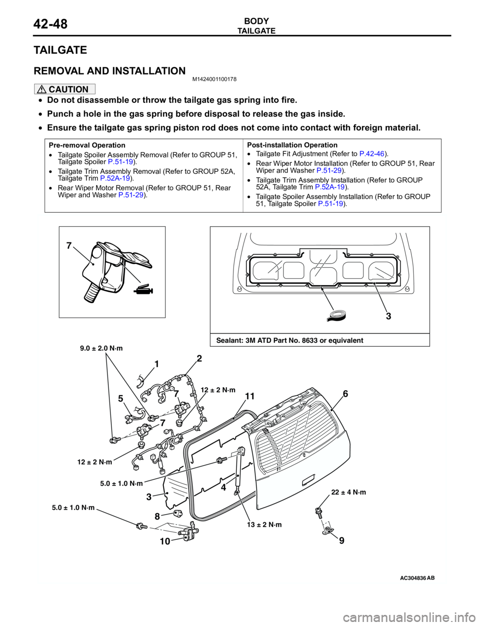
TA I L G AT E
BODY42-48
TAILGATE
REMOVAL AND INSTALLATIONM1424001100178
CAUTION
•Do not disassemble or throw the tailgate gas spring into fire.
•Punch a hole in the gas spring before disposal to release the gas inside.
•Ensure the tailgate gas spring piston rod does not come into contact with foreign material.
Pre-removal Operation
•Tailgate Spoiler Assembly Removal (Refer to GROUP 51,
Tailgate Spoiler P.51-19).
•Tailgate Trim Assembly Removal (Refer to GROUP 52A,
Tailgate Trim P.52A-19).
•Rear Wiper Motor Removal (Refer to GROUP 51, Rear
Wiper and Washer P.51-29).Post-installation Operation
•Tailgate Fit Adjustment (Refer to P.42-46).
•Rear Wiper Motor Installation (Refer to GROUP 51, Rear
Wiper and Washer P.51-29).
•Tailgate Trim Assembly Installation (Refer to GROUP
52A, Tailgate Trim P.52A-19).
•Tailgate Spoiler Assembly Installation (Refer to GROUP
51, Tailgate Spoiler P.51-19).
AC304836
7
3
4 1
6
8
12 ± 2 N·m
13 ± 2 N·m22 ± 4 N·m
AB
Sealant: 3M ATD Part No. 8633 or equivalent9.0 ± 2.0 N·m
2
712 ± 2 N·m
5
7
9
5.0 ± 1.0 N·m
5.0 ± 1.0 N·m
3
11
10
Page 327 of 788
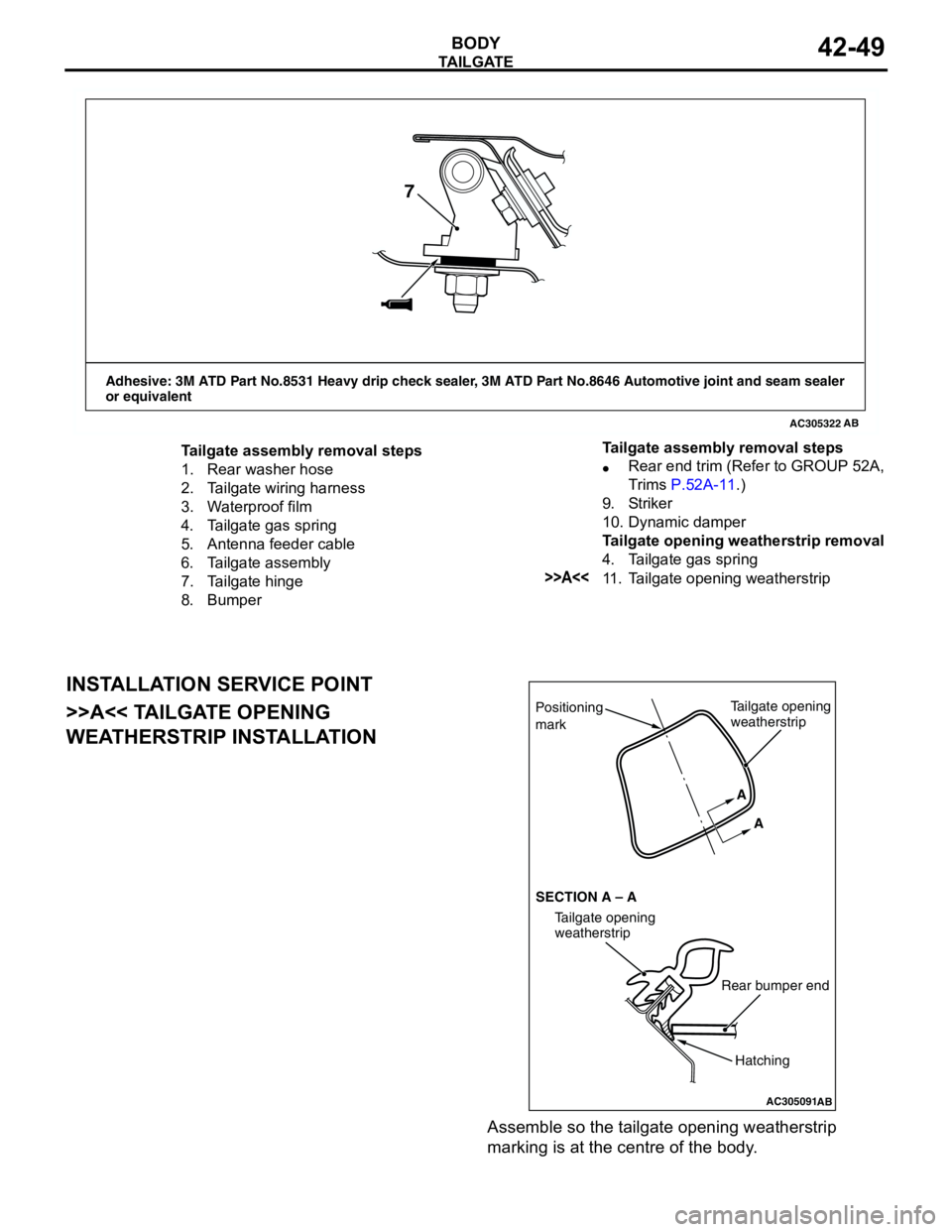
TA I L G AT E
BODY42-49
INSTALLATION SERVICE POINT
>>A<< TAILGATE OPENING
WEATHERSTRIP INSTALLATION
Assemble so the tailgate opening weatherstrip
marking is at the centre of the body.
AC305322
Adhesive: 3M ATD Part No.8531 Heavy drip check sealer, 3M ATD Part No.8646 Automotive joint and seam sealer
or equivalent
AB
7
Tailgate assembly removal steps
1. Rear washer hose
2. Tailgate wiring harness
3. Waterproof film
4. Tailgate gas spring
5. Antenna feeder cable
6. Tailgate assembly
7. Tailgate hinge
8. Bumper•Rear end trim (Refer to GROUP 52A,
Trims P.52A-11.)
9. Striker
10. Dynamic damper
Tailgate opening weatherstrip removal
4. Tailgate gas spring
>>A<<11. Tailgate opening weatherstrip Tailgate assembly removal steps
AC305091
Positioning
mark
AB
Tailgate opening
weatherstrip
Rear bumper end
Tailgate opening
weatherstrip SECTION A – AA
A
Hatching
Page 328 of 788
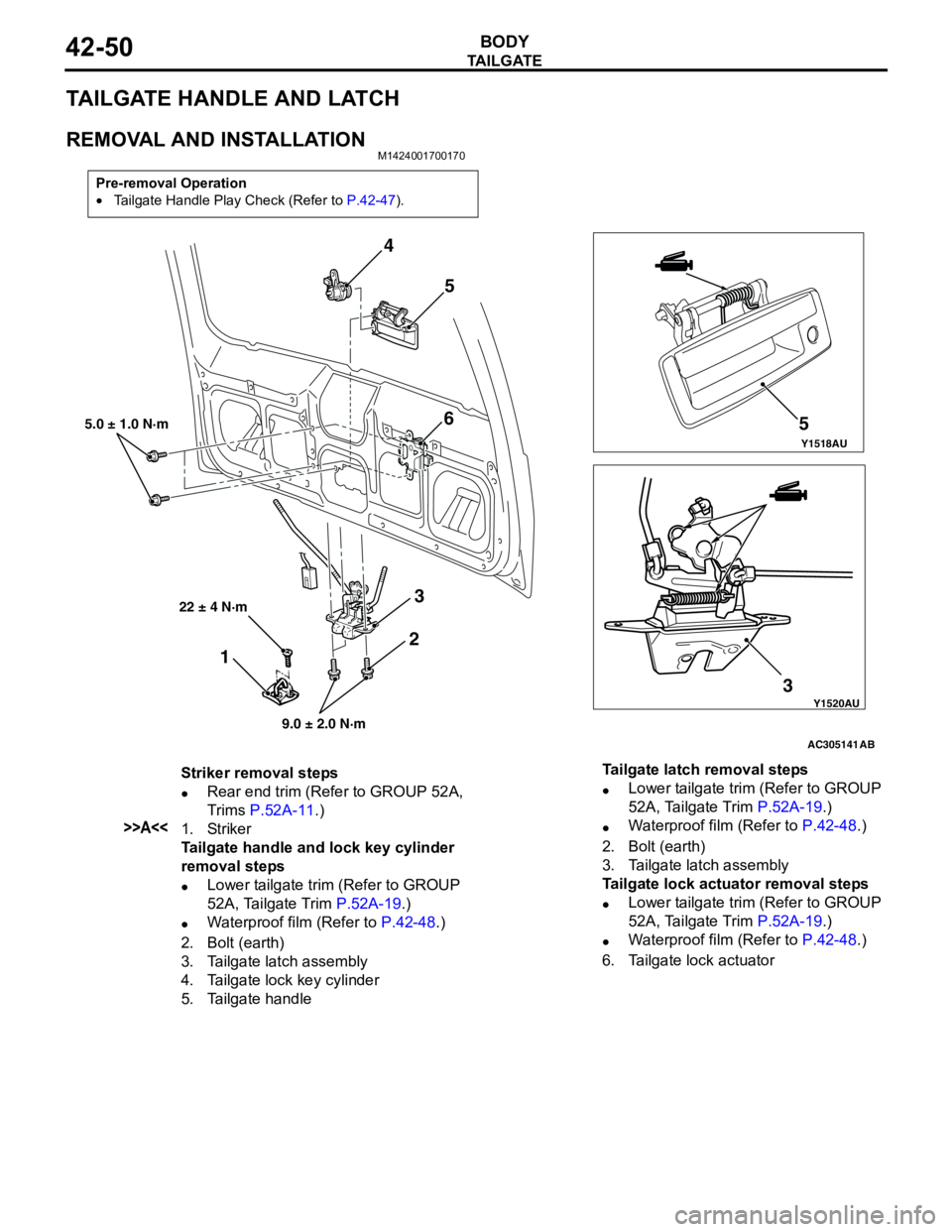
TA I L G AT E
BODY42-50
TAILGATE HANDLE AND LATCH
REMOVAL AND INSTALLATIONM1424001700170
Pre-removal Operation
•Tailgate Handle Play Check (Refer to P.42-47).
Y1518AU
Y1520AU
AC305141
4
5
6
3 35
5.0 ± 1.0 N·m
9.0 ± 2.0 N·m
AB
2
1
22 ± 4 N·m
Striker removal steps
•Rear end trim (Refer to GROUP 52A,
Trims P.52A-11.)
>>A<<1. Striker
Tailgate handle and lock key cylinder
removal steps
•Lower tailgate trim (Refer to GROUP
52A, Tailgate Trim P.52A-19.)
•Waterproof film (Refer to P.42-48.)
2. Bolt (earth)
3. Tailgate latch assembly
4. Tailgate lock key cylinder
5. Tailgate handleTailgate latch removal steps
•Lower tailgate trim (Refer to GROUP
52A, Tailgate Trim P.52A-19.)
•Waterproof film (Refer to P.42-48.)
2. Bolt (earth)
3. Tailgate latch assembly
Tailgate lock actuator removal steps
•Lower tailgate trim (Refer to GROUP
52A, Tailgate Trim P.52A-19.)
•Waterproof film (Refer to P.42-48.)
6. Tailgate lock actuator
Page 341 of 788
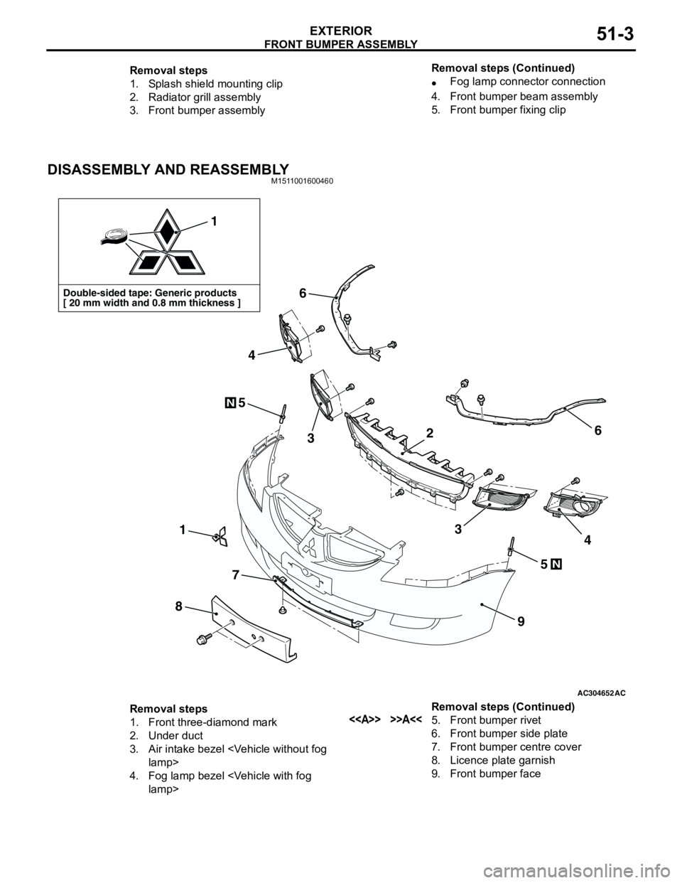
FRONT BUMPER ASSEMBLY
EXTERIOR51-3
DISASSEMBLY AND REASSEMBLYM1511001600460
Removal steps
1. Splash shield mounting clip
2. Radiator grill assembly
3. Front bumper assembly•Fog lamp connector connection
4. Front bumper beam assembly
5. Front bumper fixing clip Removal steps (Continued)
AC304652AC
Double-sided tape: Generic products
[ 20 mm width and 0.8 mm thickness ]
1
1
8
7
9
6
6
5
5
3
4
34
N
N
2
Removal steps
1. Front three-diamond mark
2. Under duct
3. Air intake bezel
4. Fog lamp bezel
6. Front bumper side plate
7. Front bumper centre cover
8. Licence plate garnish
9. Front bumper face Removal steps (Continued)
Page 343 of 788
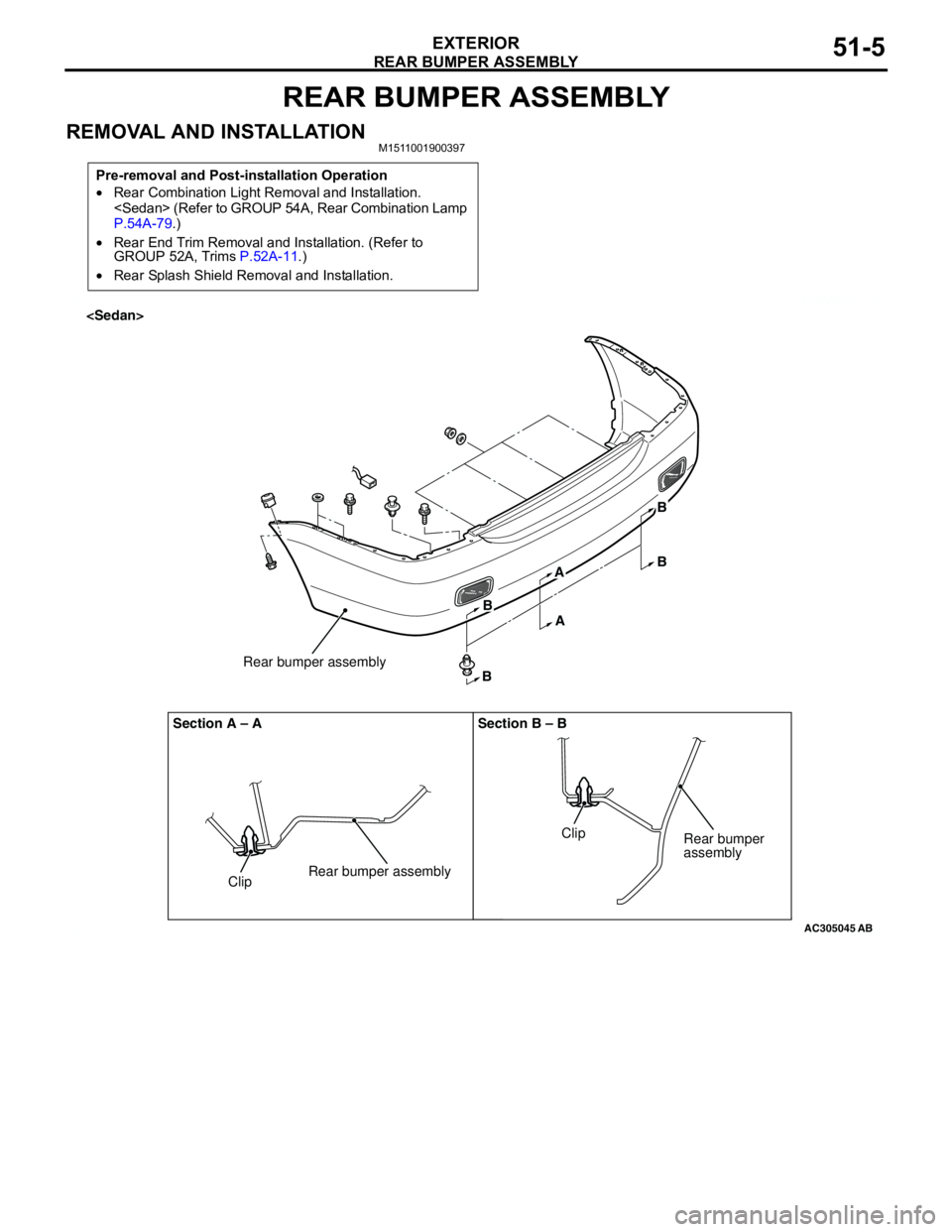
REAR BUMPER ASSEMBLY
EXTERIOR51-5
REAR BUMPER ASSEMBLY
REMOVAL AND INSTALLATIONM1511001900397
Pre-removal and Post-installation Operation
•Rear Combination Light Removal and Installation.
P.54A-79.)
•Rear End Trim Removal and Installation. (Refer to
GROUP 52A, Trims P.52A-11.)
•Rear Splash Shield Removal and Installation.
AC300413
AC305045
ClipRear bumper assemblyRear bumper assembly Section A – A Section B – B
ClipRear bumper
assembly
AB
B
BA
AB
B
Page 357 of 788
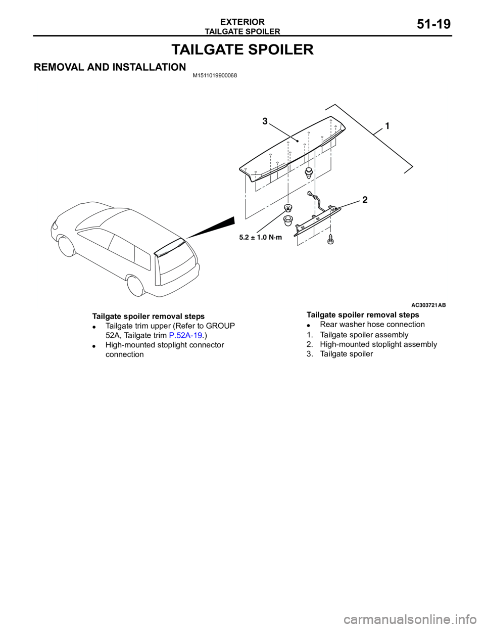
TAILGATE SPOILER
EXTERIOR51-19
TAILGATE SPOILER
REMOVAL AND INSTALLATIONM1511019900068
AC303721
1
2 3
AB
5.2 ± 1.0 N·m
Tailgate spoiler removal steps
•Tailgate trim upper (Refer to GROUP
52A, Tailgate trim P.52A-19.)
•High-mounted stoplight connector
connection•Rear washer hose connection
1. Tailgate spoiler assembly
2. High-mounted stoplight assembly
3. Tailgate spoiler Tailgate spoiler removal steps
Page 367 of 788
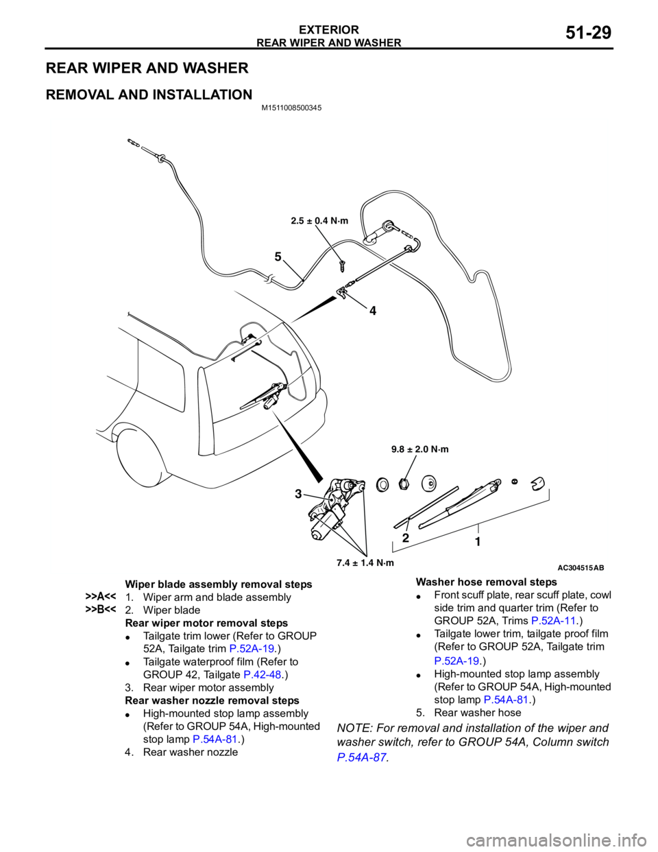
REAR WIPER AND WASHER
EXTERIOR51-29
REAR WIPER AND WASHER
REMOVAL AND INSTALLATION
M1511008500345
NOTE: For removal and installation of the wiper and
washer switch, refer to GROUP 54A, Column switch
P.54A-87.
AC304515
2.5 ± 0.4 N·m
9.8 ± 2.0 N·m
7.4 ± 1.4 N·m
3
2
1 4
5
AB
Wiper blade assembly removal steps
>>A<<1. Wiper arm and blade assembly
>>B<<2. Wiper blade
Rear wiper motor removal steps
•Tailgate trim lower (Refer to GROUP
52A, Tailgate trim P.52A-19.)
•Tailgate waterproof film (Refer to
GROUP 42, Tailgate P.42-48.)
3. Rear wiper motor assembly
Rear washer nozzle removal steps
•High-mounted stop lamp assembly
(Refer to GROUP 54A, High-mounted
stop lamp P.54A-81.)
4. Rear washer nozzleWasher hose removal steps
•Front scuff plate, rear scuff plate, cowl
side trim and quarter trim (Refer to
GROUP 52A, Trims P.52A-11.)
•Tailgate lower trim, tailgate proof film
(Refer to GROUP 52A, Tailgate trim
P.52A-19.)
•High-mounted stop lamp assembly
(Refer to GROUP 54A, High-mounted
stop lamp P.54A-81.)
5. Rear washer hose
Page 383 of 788
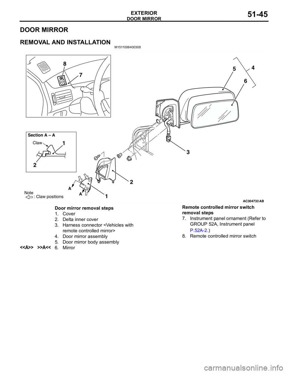
DOOR MIRROR
EXTERIOR51-45
DOOR MIRROR
REMOVAL AND INSTALLATIONM1511006400308
AC304733
Note
: Claw positions
AB
A
A Section A – A
Claw1
2
1234
5
6 7 8
Door mirror removal steps
1. Cover
2. Delta inner cover
3. Harness connector
4. Door mirror assembly
5. Door mirror body assembly
<> >>A<<6. MirrorRemote controlled mirror switch
removal steps
7. Instrument panel ornament (Refer to
GROUP 52A, Instrument panel
P.52A-2.)
8. Remote controlled mirror switch
Page 387 of 788

52-1
GROUP 52
INTERIOR AND
SUPPLEMENTAL
RESTRAINT
SYSTEM(SRS)
CONTENTS
INTERIOR . . . . . . . . . . . . . . . . . . . . . . . . . . . . . . . . . . . . . . . . . .52A
SUPPLEMENTAL RESTRAINT SYSTEM (SRS) . . . . . . . . . . . .52B
Page 462 of 788
FOG LAMP
CHASSIS ELECTRICAL54A-74
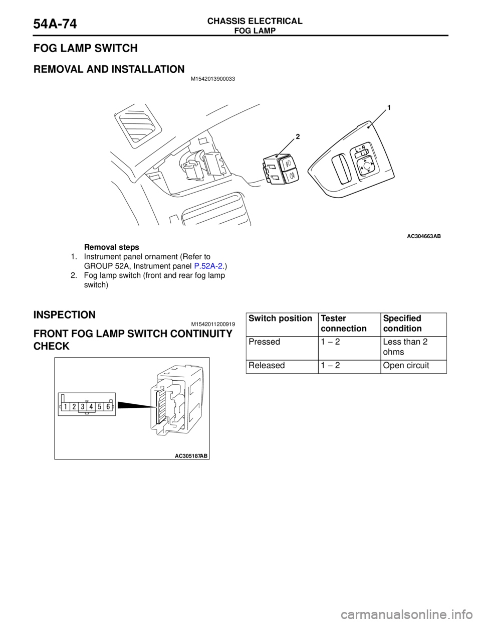
FOG LAMP SWITCH
REMOVAL AND INSTALLATIONM1542013900033
INSPECTIONM1542011200919
FRONT FOG LAMP SWITCH CONTINUITY
CHECK
AC304663AB
21
Removal steps
1. Instrument panel ornament (Refer to
GROUP 52A, Instrument panel P.52A-2.)
2. Fog lamp switch (front and rear fog lamp
switch)
AC305187
AB
Switch position Tester
connectionSpecified
condition
Pressed 1 − 2 Less than 2
ohms
Released 1 − 2 Open circuit